EMBEDDED PROGRAMMING

This week, I worked on embedded programming, which involves competencies in various aspects such as programming languages, debugging and testing, as well as an understanding of hardware and operating systems.

Group Assignment

As part of the group assignment, Dr. Sujit and I conducted a study that included the following tasks:

Objectives of the Study

Comparison of Toolchains – To analyze and compare different embedded system toolchains based on their functionality, compatibility, and efficiency in various development environments.

Evaluation of Development Workflows –To examine the development workflows for different embedded architectures, assessing factors such as ease of use, debugging capabilities, and optimization techniques.

Identification of Best Practices –To identify best practices for selecting and utilizing toolchains and workflows, ensuring optimal performance, reduced development time, and enhanced reliability in embedded system projects.

Architectures

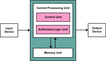
1. Von Neumann Architecture:

Definition: A computing architecture in which program instructions and data share the same memory space.

Characteristics: This architecture follows a sequential processing model, utilizing a single shared bus for both instructions and data. The CPU retrieves instructions from memory, decodes them, and executes them in sequence.

Bugs/Limitations: A key limitation is the Von Neumann bottleneck, where the shared bus for data and instructions can create a performance constraint, potentially slowing down the CPU and limiting overall system throughput.

Image

2. Harvard Architecture:

Definition: Unlike the Von Neumann architecture, this design features separate memory storage for data and instructions, enabling simultaneous access to both.

Advantages: Enhances performance by eliminating the Von Neumann bottleneck, allowing data and instructions to be fetched concurrently.

Usage: Commonly implemented in embedded systems and specialized processors for improved efficiency and speed.

Image

Von-Neumann Architecture Vs Harvard Architecture

Image

3. RISC (Reduced Instruction Set Computing):

Definition: A CPU architecture that uses a small, highly optimized set of instructions.

Features: Simple, fast instructions, making it suitable for pipelining and improving execution speed.

Examples: ARM, MIPS.

4. CISC (Complex Instruction Set Computing):

Definition: A CPU architecture with a large set of instructions, which can execute complex operations in a single instruction.

Features: More powerful instructions but less efficient due to longer execution cycles.

Examples: x86.

CISC Vs RISC

Image

5. Microprocessor:

Definition: A central processing unit (CPU) on a single integrated circuit (IC), capable of executing a set of instructions and performing computation tasks.

Usage: Used in general-purpose computing like PCs, laptops, servers.

6. Microcontroller:

Definition: A small computer on a single chip, often including a CPU, memory, and I/O peripherals.

Features: Found in embedded systems, IoT devices, robotics, and home appliances. It’s designed for real-time, embedded applications.

Microprocessor Vs Microcontroller

Image

7. Multi-core:

Definition: Refers to processors that have more than one core (processing unit) on a single chip, allowing parallel execution of tasks.

Advantages: Increases performance and multitasking capabilities, reducing latency and power consumption.

8. GPU (Graphics Processing Unit):

Definition: A specialized processor for rendering graphics and handling parallel computing tasks.

Features: Designed for highly parallel tasks, ideal for graphics, machine learning, and scientific computations.

Usage: Used in gaming, deep learning, image processing, etc.

9. Embedded Systems:

An embedded system is a combination of computer hardware and software designed for a specific function. Embedded systems might also function within a larger system. These systems can be programmable or have a fixed functionality.

Definition: Specialized computing systems designed to perform a dedicated function within a larger system.

Characteristics: Often optimized for real-time operations and low power consumption.

Examples: Microcontrollers, IoT devices, automotive systems.

Image

Memory

Image

Peripherals

Image

Word Size

Image

Processor Families

Image

Microcontrollers

A microcontroller is a compact integrated circuit designed to perform specific tasks within an embedded system. It consists of a processor (CPU), memory (RAM, ROM/Flash), and input/output (I/O) peripherals, all integrated into a single chip. Microcontrollers are widely used in automation, control systems, and consumer electronics due to their efficiency, low power consumption, and real-time processing capabilities.

Arduino Uno

Arduino is an open-source microcontroller platform that integrates hardware, software, and programming tools. It is designed with a focus on simplicity, making microcontroller-based development accessible to a wide audience. The platform serves as an excellent educational tool, enabling users to learn and experiment with embedded systems efficiently.

The Arduino® UNO R3 is an ideal development board for beginners to explore electronics and programming. It features the widely used ATmega328P microcontroller along with the ATmega16U2 processor for USB-to-serial communication. This versatile board offers an excellent introduction to the Arduino ecosystem, providing a seamless and user-friendly experience for learning and prototyping.

Image

Technical Specification

Microcontroller : ATmega328

Operating Voltage : 5V

Input Voltage (recommended) : 7-12V

Input Voltage (limits) : 6-20V

Digital I/O Pins : 14 (of which 6 provide PWM output)

Analog Input Pins : 6

DC Current per I/O Pin : 40 mA

DC Current for 3.3V Pin : 50 mA

Flash Memory : 32 KB of which 0.5 KB used by bootloader

SRAM : 2 KB

EEPROM : 1 KB

Clock Speed : 16 MHz

Length : 68.6 mm

Width : 53.4 mm

Weight : 25 g

Connector Pinouts

Image

Analog Pins

Image

Digital Pins

Image

Referances

Image

Arduino Mega

The Arduino Mega 2560 is a powerful microcontroller board designed for complex and large-scale projects that require more I/O pins and processing capability. It is based on the ATmega2560 microcontroller and offers expanded memory, additional communication interfaces, and increased functionality compared to the Arduino Uno.

The Arduino® Mega 2560 Rev3 is a high-performance development board designed for building large-scale applications, offering greater capability compared to other Arduino maker boards. It is powered by the ATmega2560 microcontroller, operating at a 16 MHz clock frequency.

The board features 54 digital input/output pins, 16 analog inputs, 4 UARTs (hardware serial ports), a USB connection, a power jack, an ICSP header, and a reset button, making it ideal for complex projects requiring extensive connectivity and processing power.

Image

Technical Specification

Microcontroller: ATmega2560

Operating Voltage: 5V

Input Voltage (recommended): 7-12V

Input Voltage (limit): 6-20V

Digital I/O Pins: 54 (of which 15 provide PWM output)

Analog Input Pins: 16

DC Current per I/O Pin: 20 mA

DC Current for 3.3V Pin: 50 mA

Flash Memory: 256 KB of which 8 KB used by bootloader

SRAM: 8 KB

EEPROM: 4 KB

Clock Speed: 16 MHz

LED_BUILTIN: 13

Length: 101.52 mm

Width: 53.3 mm

Weight: 37 g

>

Connector Pinouts

Image

Analog Pins

Image

Digital Pins

Image

Referances

Image

ESP WROOM 32

The ESP32-WROOM-32 is a highly versatile Wi-Fi + Bluetooth® + Bluetooth LE MCU module designed for a wide range of applications, from low-power sensor networks to high-performance tasks such as voice encoding, music streaming, and MP3 decoding.

At the core of this module is the ESP32-D0WDQ6 chip, which is designed to be scalable and adaptive. It features dual CPU cores, which can be controlled independently, with a configurable clock frequency ranging from 80 MHz to 240 MHz. Additionally, the chip includes a low-power coprocessor, which can handle peripheral monitoring and other lightweight tasks while conserving power by reducing CPU usage.

The ESP32 also integrates a rich set of peripherals, including capacitive touch sensors, an SD card interface, Ethernet, high-speed SPI, UART, I²S, and I²C, making it a powerful and efficient choice for embedded and IoT applications.

Image

Technical Specification

ESP32-WROOM-32 contains two low-power Xtensa 32-bit LX6 microprocessors

448 KBytes ROM for booting and core functions

520 KBytes on-chip SRAM

8 KBytes SRAM in RTC SLOW

8 KBytes SRAM in RTC FAST

1 Kbit of EFUSE, 256 bits MAC

WiFi: 802.11 b/g/n/d/e/i/k/r (802.11n up to 150 Mbps)

Bluetooth v4.2 BR/EDR and BLE specification

Wi-Fi mode Station/softAP/SoftAP+station/P2P

Security WPA/WPA2/WPA2-Enterprise/WPS

Encryption AES/RSA/ECC/SHA

IPv4, IPv6, SSL, TCP/UDP/HTTP/FTP/MQTT

Interfaces: SD-card, UART,SPI,SDIO,I2C,LED PWM,Motor PWM,I2S ,IR,GPIO, capacitive touch sensor, ADC, DAC, Hall sensor, temperature sensor

Operating temperature -40 + 85C

Operating voltate: 2.2-3.6V

Consumption: 80 mA typ

Dimensions: 18 mm(L) x 25.5 mm(W) x 2.8 mm(H)

Pin pitch:1.27mm

Shielding can height: 2 mm

PCB tickness: 0.8±0.1mm

Connector Pinouts

Image

Pin Description

Image

XIAO ESP32 C3

The Seeed Studio XIAO ESP32C3 is a compact and versatile IoT mini development board based on the Espressif ESP32-C3 Wi-Fi/Bluetooth dual-mode chip. The ESP32-C3 features a 32-bit RISC-V CPU with an integrated Floating Point Unit (FPU), enabling high-performance 32-bit single-precision alculations. It offers excellent radio frequency performance, supporting IEEE 802.11 b/g/n Wi-Fi and Bluetooth 5 (BLE) protocols.

This board is equipped with an external antenna to enhance signal strength for wireless applications. Its compact and custom form factor, along with a single-sided surface-mountable layout, makes it ideal for space-constrained projects. The XIAO ESP32C3 provides a rich set of interfaces, including 11 digital I/O pins (PWM capable), 3 analog I/O pins (ADC capable), and four serial interfaces (UART, I²C, and SPI). Additionally, it includes a reset button and a bootloader mode button for ease of development.

The XIAO ESP32C3 is fully compatible with the Grove Shield for Seeeduino XIAO and the Seeeduino XIAO Expansion Board, with the exception of SWD spring contacts, which are incompatible with the expansion board.

With its cost-efficiency, high performance, and low power consumption, the XIAO ESP32C3 is an excellent choice for wireless wearable applications and low-power IoT solutions.

Image

Connector Pinouts

Image

Functional Block Diagram

Image

Pinout and Schematics

Image

Features

Powerful CPU: ESP32-C3, 32­bit RISC­-V single­core processor that operates at up to 160 MHz

Complete Wi­Fi subsystem: Complies with IEEE 802.11b/g/n protocol and supports Station mode, SoftAP mode, SoftAP + Station mode, and promiscuous mode

Bluetooth LE subsystem: Supports features of Bluetooth 5 and Bluetooth mesh

Ultra-Low Power: Deep sleep power consumption is about 43μA

Better RF performance: External RF antenna included

Battery charging chip: Supports lithium battery charge and discharge management

Rich on-chip resources: 400KB of SRAM, and 4MB of on-board flash memory

Ultra small size: As small as a thumb(21x17.8mm) XIAO series classic form-factor for wearable devices and small projects

Reliable security features: Cryptographic hardware accelerators that support AES-128/256, Hash, RSA, HMAC, digital signature and secure boot

Rich interfaces: 1xI2C, 1xSPI, 2xUART, 11xGPIO(PWM), 4xADC, 1xJTAG bonding pad interface

Single-sided components, surface mounting design

XIAO RP2040

The Seeed Studio XIAO RP2040 is a compact yet powerful development board, similar in size to the Seeed Studio XIAO SAMD21, but with significantly enhanced performance. It is powered by the dual-core RP2040 processor, which supports a flexible clock speed of up to 133 MHz, making it an efficient low-power microcontroller.

The board features 264 KB of SRAM and 2 MB of onboard Flash memory, providing ample storage for programs and applications. Despite its compact size, the XIAO RP2040 delivers impressive processing capabilities while maintaining low power consumption, making it ideal for battery-operated and wearable devices.

Measuring only 21 x 17.8 mm—comparable to a thumb—this board is well-suited for wearable electronics, miniaturized projects, and embedded applications.

Image

Features

Powerful MCU: Dual-core ARM Cortex M0+ processor, flexible clock running up to 133 MHz

Rich on-chip resources: 264KB of SRAM, and 2MB of on-board Flash memory

Flexible compatibility: Support Micropython/Arduino/CircuitPython

Easy project operation: Breadboard-friendly & SMD design, no components on the back

Small size: As small as a thumb(21x17.8mm) for wearable devices and small projects.

Multiple interfaces: 11 digital pins, 4 analog pins, 11 PWM Pins,1 I2C interface, 1 UART interface, 1 SPI interface, 1 SWD Bonding pad interface

A system overview of the RP2040 chip

Image

Connection Pin out

Image

Pin Descriptions

Image
Image

Conclusion

Through the study of various microcontrollers, including the Arduino® Uno, Arduino Mega, ESP32-WROOM-32, XIAO ESP32C3, and XIAO RP2040, it is evident that each board offers unique features tailored to different applications.

The Arduino Uno serves as an excellent entry-level microcontroller, providing a user-friendly development platform for beginners.

The Arduino Mega expands on this by offering more I/O pins and memory, making it suitable for complex projects requiring extensive connectivity.

The ESP32-WROOM-32 stands out for its built-in Wi-Fi and Bluetooth capabilities, making it ideal for IoT applications and wireless communication.

The XIAO ESP32C3 further enhances IoT development with a RISC-V architecture, low power consumption, and compact form factor, making it an excellent choice for wearable and embedded applications.

The XIAO RP2040, powered by a dual-core processor, provides efficient performance and low power usage, making it well-suited for miniaturized, high-performance projects.

The group assignment is linked here

Individual Assignment

During my study of the Arduino® Uno, Arduino Mega, ESP32-WROOM-32, XIAO ESP32C3, and XIAO RP2040 microcontrollers, I selected the ESP32C3 and XIAO RP2040 for my individual assignment. These microcontrollers were chosen for embedded programming using Arduino IDE and MicroPython on Thonny, allowing for a comprehensive exploration of their capabilities in different programming environments.

Objectives of the Study

1. To implement embedded programming on the ESP32C3 and XIAO RP2040 using Arduino IDE and MicroPython on Thonny, exploring their compatibility and functionality.

2. To compare and analyze the performance, efficiency, and ease of development of both microcontrollers in different programming environments.

3. To develop and test embedded applications utilizing the key features of ESP32C3 and XIAO RP2040, including their communication interfaces, processing capabilities, and power efficiency.

1. XIAO RP2040

RP2040 is a low-cost, high-performance microcontroller device with flexible digital interfaces. Key features:

• Dual Cortex M0+ processor cores, up to 133 MHz

• 264 kB of embedded SRAM in 6 banks

• 30 multifunction GPIO

• 6 dedicated IO for SPI Flash (supporting XIP)

• Dedicated hardware for commonly used peripherals

• Programmable IO for extended peripheral support

• 4 channel ADC with internal temperature sensor, 0.5 MSa/s, 12 bit conversion

I. Programming using C++

Step 1: Setting Up Programming for XIAO RP2040

To program the XIAO RP2040, the first step is to choose C++ as the programming language. For this purpose, Arduino IDE is required. Therefore, the installation process of Arduino IDE is initiated to set up the development environment.

Image

Step 2: Installing Arduino IDE and Configuring Board Manager

Install Arduino IDE on a laptop or PC. Once the installation is complete, navigate to File Menu → Preferences. In the Additional Boards Manager URLs field, enter the following URL:

https://github.com/earlephilhower/arduino-pico/releases/download/global/package_rp2040_index.json

This step ensures proper configuration for supporting XIAO RP2040 in Arduino IDE.

Image

Step 3: Installing the RP2040 Board Package

Navigate to Tools → Board → Boards Manager... and enter "RP2040" in the search bar. From the search results, select the latest version of "Raspberry Pi Pico/RP2040" and proceed with the installation. This step ensures that the XIAO RP2040 is properly supported in Arduino IDE for programming and development.

Image
Image

Step 4: Selecting the Seeed Studio XIAO RP2040 Board

After successfully installing the board package, navigate to Tools → Board, locate "Seeed Studio XIAO RP2040", and select it. This completes the setup process for using the Seeed Studio XIAO RP2040 with Arduino IDE, making it ready for programming and development.

Image

Step 5: Identifying the COM Port

To locate the correct COM port, follow these steps:

1. Right-click on This PC and select Manage.

2. In the Computer Management window, navigate to Device Manager.

3. Expand the Ports (COM & LPT) section to view the connected devices.

This process allows you to identify the correct port to be used for programming the Seeed Studio XIAO RP2040 in Arduino IDE.

Image

Step 6: Selecting the COM Port

Navigate to Tools → Port and select the serial port corresponding to the connected Seeed Studio XIAO RP2040. This is typically COM3 or higher, as COM1 and COM2 are usually reserved for hardware serial ports. The correct port for the XIAO RP2040 is identifiable by the presence of "Seeed Studio XIAO RP2040" in parentheses next to the port name.

Image

Step 7: Program For Buzzer

/*buzzer by XIAO RP2040

Turns an buzzer on for two second, then off for otwo second, repeatedly.

pin D0 if RP2040 is define as output pin & used to connect the buzzer.

This program is written by Dr. Shantanu Kadam

*/

// the setup function runs once when you press reset or power the board

void setup() {

// initialize digital pin LED_BUILTIN as an output.

pinMode(D0, OUTPUT);

}

// the loop function runs over and over again forever

void loop()

{digitalWrite(D0, HIGH); // turn the LED on (HIGH is the voltage level)

delay(2000); // wait for a second

digitalWrite(D0, LOW); // turn the LED off by making the voltage LOW

delay(2000); // wait for a second

}

I have written a C++ program to control a buzzer. The buzzer is powered for two seconds, producing sound, then remains off for the next two seconds. This cycle repeats continuously.

OUTPUT

Step 7: Program For Blinking

/*Blink using Seeed RP2040

Turns an LED on for one second, then off for one second, repeatedly.

This program is written by Dr. Shantanu Kadam

*/

// the setup function runs once when you press reset or power the board

void setup() {

// initialize digital pin LED_BUILTIN as an output.

pinMode(LED_BUILTIN, OUTPUT);

}

// the loop function runs over and over again forever

void loop() {

digitalWrite(LED_BUILTIN, HIGH); // turn the LED on (HIGH is the voltage level)

delay(1000); // wait for a second

digitalWrite(LED_BUILTIN, LOW); // turn the LED off by making the voltage LOW

delay(1000); // wait for a second

}

I have written a C++ program to control a power LED. The LED receives power for one second, causing it to blink, then turns off for the next second. This cycle repeats continuously.

II. Programming using MicroPython on Thonny Editor

Step 1: Downloading and Installing Thonny Editor

Download and install the latest version of Thonny Editor compatible with your operating system. Ensure that you select the appropriate version based on your system requirements to enable seamless development and execution of MicroPython programs.

Image
Image

Step 2: Configuring Thonny Editor

Launch Thonny Editor, then navigate to Tools → Options to open the settings menu. This allows you to configure the necessary preferences for MicroPython development.

Image

Step 3: Configuring the Interpreter in Thonny

In the Options menu, navigate to the "Interpreter" tab. Set the interpreter to "MicroPython (Raspberry Pi Pico)" and choose "Try to detect port automatically" for the port selection. This ensures proper communication between Thonny and the XIAO RP2040 for MicroPython programming.

Image

Step 4: Connecting Seeed Studio XIAO RP2040 and Installing MicroPython

1. Press and hold the "BOOT" button on the Seeed Studio XIAO RP2040.

2.While holding the button, connect the board to the PC using a Type-C cable.

3. If the connection is successful, a new "RPI-RP2" drive will appear on the PC.

4. Click on "Install or update MicroPython" in Thonny to install the necessary firmware.

Image

Step 5: Installing MicroPython Firmware

1. Click on the "Install" button to begin the MicroPython installation process.

2. Wait for the installation to complete. Once the status displays "Done", close the installation window.

3. After successful installation, the Thonny interface will display confirmation messages indicating that the firmware is ready for use.

Image

Step 6: Copy the following codes to Thonny.

import neopixel

This code is written by Dr. Shantanu Kadam

import utime

import machine

# Power pin setup

power = machine.Pin(11, machine.Pin.OUT)

power.value(1) # Enable power

# Define colors

BLACK = (0, 0, 0)

RED = (255, 0, 0)

YELLOW = (255, 150, 0)

GREEN = (0, 255, 0)

CYAN = (0, 255, 255)

BLUE = (0, 0, 255)

PURPLE = (180, 0, 255)

WHITE = (255, 255, 255)

COLORS = [BLACK, RED, YELLOW, GREEN, CYAN, BLUE, PURPLE, WHITE]

# Initialize WS2812 LED strip using neopixel (pin 12, 1 LED)

led = neopixel.NeoPixel(machine.Pin(12), 1) # NeoPixel(pin, number_of_leds)

while True:

print("Beautiful colors")

for color in COLORS:

led[0] = color # Set LED to color

led.write() # Update LED

utime.sleep(0.2) # Wait 200ms

Step 7: Upload the Code

Click the "Run current script" button to upload the code.

Click the "Run current script" button to upload the code.

For the first-time upload, Thonny will prompt you to choose where to save the script. You can select either "This Computer" or "Raspberry Pi Pico".

Image

If the upload is successful, the RGB LED will cycle through different colors and flash accordingly. Additionally, the text "Beautiful Color" will be displayed in the Shell output window.

OUTPUT

2. XIAO ESP32C3

The Seeed Studio XIAO ESP32C3 is a compact IoT development board built on the Espressif ESP32-C3 WiFi/Bluetooth dual-mode chip. The ESP32-C3 features a 32-bit RISC-V CPU with an integrated Floating Point Unit (FPU), enabling efficient 32-bit single-precision arithmetic for high-performance computing.

This board offers excellent radio frequency performance, supporting IEEE 802.11 b/g/n WiFi and Bluetooth 5 (LE) protocols. To enhance wireless connectivity, it includes an external antenna, improving signal strength for various applications.

Designed with a compact, single-sided surface-mountable form factor, the XIAO ESP32C3 provides a versatile range of interfaces. It features:

1. 11 digital I/O pins, configurable as PWM outputs.

2. 4 analog I/O pins, functioning as ADC inputs.

Additionally, the board is equipped with a reset button and a bootloader mode button, making it convenient for firmware updates and debugging. With its small size, low power consumption, and powerful capabilities, the Seeed Studio XIAO ESP32C3 is an ideal choice for IoT applications, embedded systems, and wireless communication projects.

I. Programming using C++

Step 1: Setting Up the Arduino IDE for ESP32

1. Download and Install the latest version of the Arduino IDE compatible with your operating system.

2. Launch the Arduino application after installation.

3. Add the ESP32 board package to the Arduino IDE:

4. Navigate to File > Preferences.

In the "Additional Boards Manager URLs" field, enter the following URL:

https://raw.githubusercontent.com/espressif/arduino-esp32/gh-pages/package_esp32_index.json

Click OK to save the changes.

This process enables support for ESP32-based microcontrollers in the Arduino IDE, allowing you to program and develop applications efficiently.

Image

Step 2: Install the ESP32 Board Package

Open the Arduino IDE.

Navigate to Tools > Board > Boards Manager.

In the search box, type "esp32".

Locate the ESP32 by Espressif Systems package.

Select the latest version from the dropdown menu.

Click Install and wait for the installation to complete.

Once installed, the ESP32 boards will be available in the Boards menu, allowing you to program ESP32-based microcontrollers.

Image

Step 3: Select Your Board and Port

1. Open the Arduino IDE.

2. Navigate to Tools > Board > ESP32 Arduino.

3. Scroll down to the bottom of the list and select "XIAO_ESP32C3".

4. Navigate to Tools > Port and select the appropriate COM port for the connected XIAO ESP32C3.

Now, your board is ready for programming in the Arduino IDE.

Image
Image

Step 4: Copy the following code of C++ for ESP32C3

This code is written by Dr. Shantanu Kadam

// the setup function runs once when you press reset or power the board

void setup() {

// initialize digital pin LED_BUILTIN as an output.

pinMode(D2, OUTPUT);

}

// the loop function runs over and over again forever

void loop() {

digitalWrite(D2, HIGH); // turn the LED on (HIGH is the voltage level)

delay(2000); // wait for a second

digitalWrite(D2, LOW); // turn the LED off by making the voltage LOW

delay(1000); // wait for a second

}

This C++ program is designed for a 5V motor on an ESP32-C3 board. The motor runs for two seconds and then stops for one second in a continuous cycle.

OUTPUT


FAB ACADEMY - Dr. Shantanu Kadam Image