Week 3
COMPUTER CONTROLLED CUTTING
Computer-controlled cutting is an advanced digital fabrication technique that utilizes computer-guided machines to achieve precise and efficient cutting or engraving of materials. Two widely used tools in this category are laser cutting machines and vinyl cutters, each serving distinct roles in design, prototyping, and manufacturing. These machines operate using vector-based design software such as Adobe Illustrator, Inkscape, or CorelDRAW to generate precise cutting paths. Their applications span from artistic and creative projects to industrial-scale production, making them indispensable in digital fabrication labs, makerspaces, and commercial workshops.
This week, I am working with two computer-controlled cutting machines as part of two types of assignments:
Group Assignment
Individual Assignment
Group Assignment
As part of the group assignment, Dr. Sujit and I conducted a study that included the following tasks:
1. Completing the lab's safety training.
2. Characterizing the laser cutter's parameters, including focus, power, speed, cutting rate, kerf, joint clearance, and various cutting types.
The group assignment is linked here
Individual Assignment
While working on the group assignment, I gained valuable insights into laser cutting technology. Building on this knowledge, I explored the functionalities and applications of both the laser cutting machine and the vinyl cutter as part of my individual assignment. This hands-on experience allowed me to understand their working principles, operational parameters, and practical applications in digital fabrication.
PARAMETRIC DESIGN WITH SOLD WORK
Last week, I explored two different 3D design software programs. However, for this week's assignment, I chose to use SolidWorks. I began by opening the SolidWorks user interface and starting the 2D drawing.
I want to work with a laser cutting machine, which requires a 2D project model. I have a project in mind, and using my imagination and critical thinking, I have started working on the design. I began with the connecting part, which has a width of 15mm and various angles, including 90°, 109°, 117°, and 125°. Additionally, I designed several joint connections, calculated using my mathematical and design knowledge.
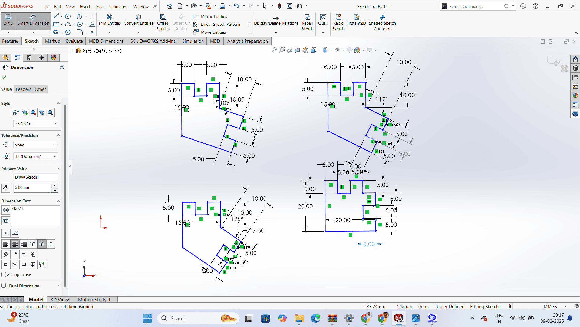
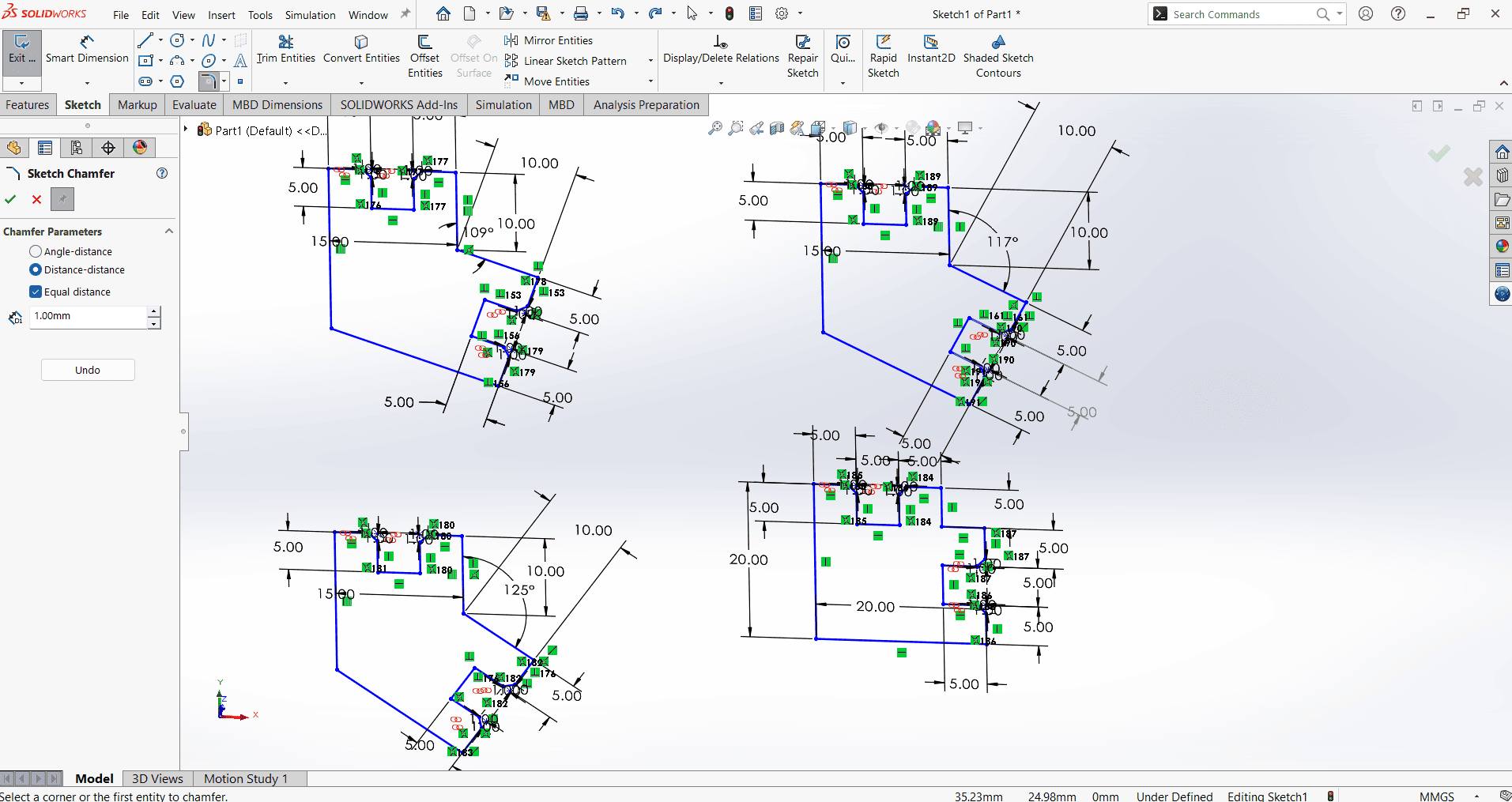
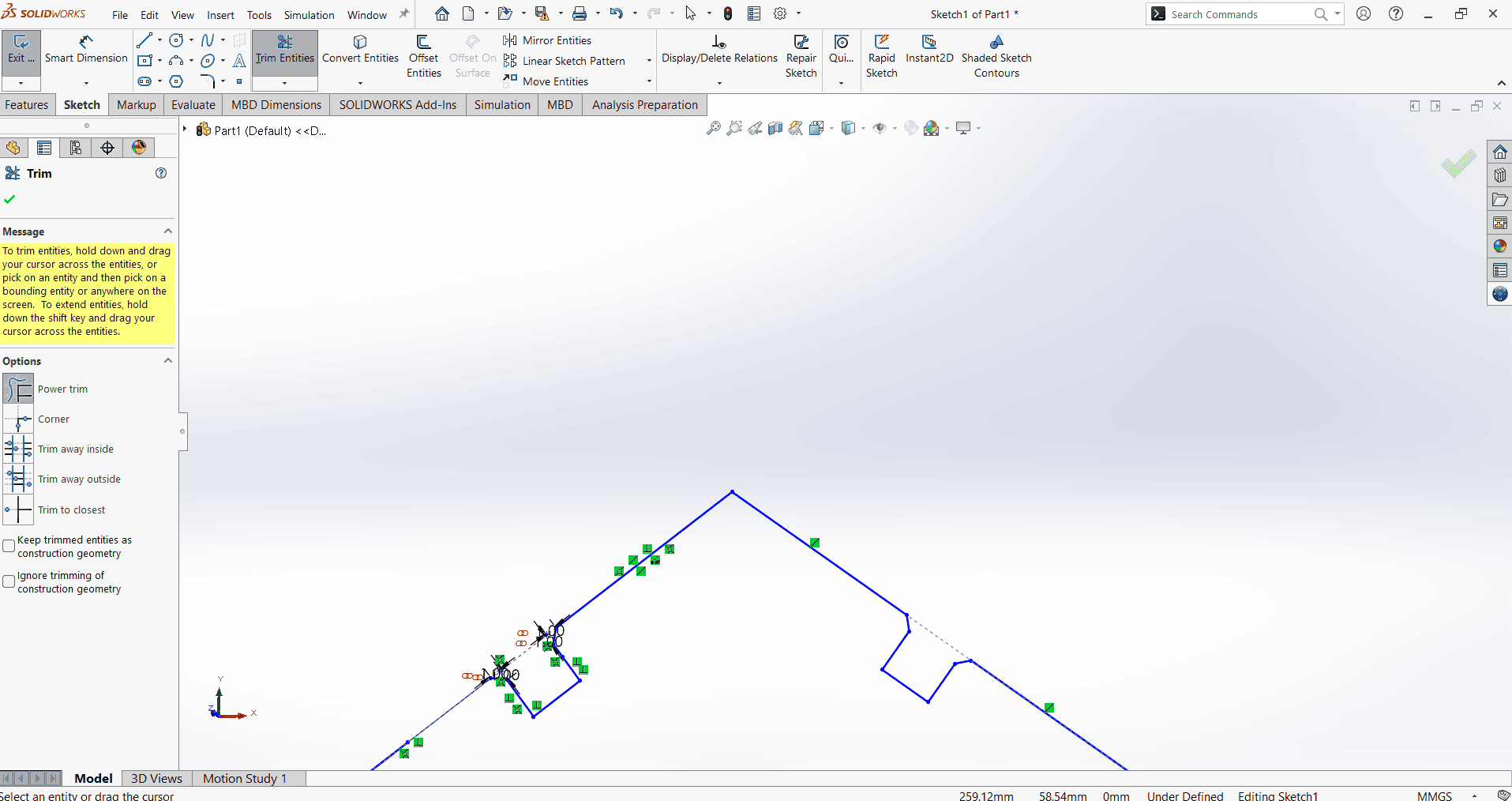
To ensure easy fitting of the parts, adding a chamfer is essential to some extent. In the SolidWorks drawing, I used the Chamfer command to add a 1mm chamfer to the 5mm × 5mm joint connections.
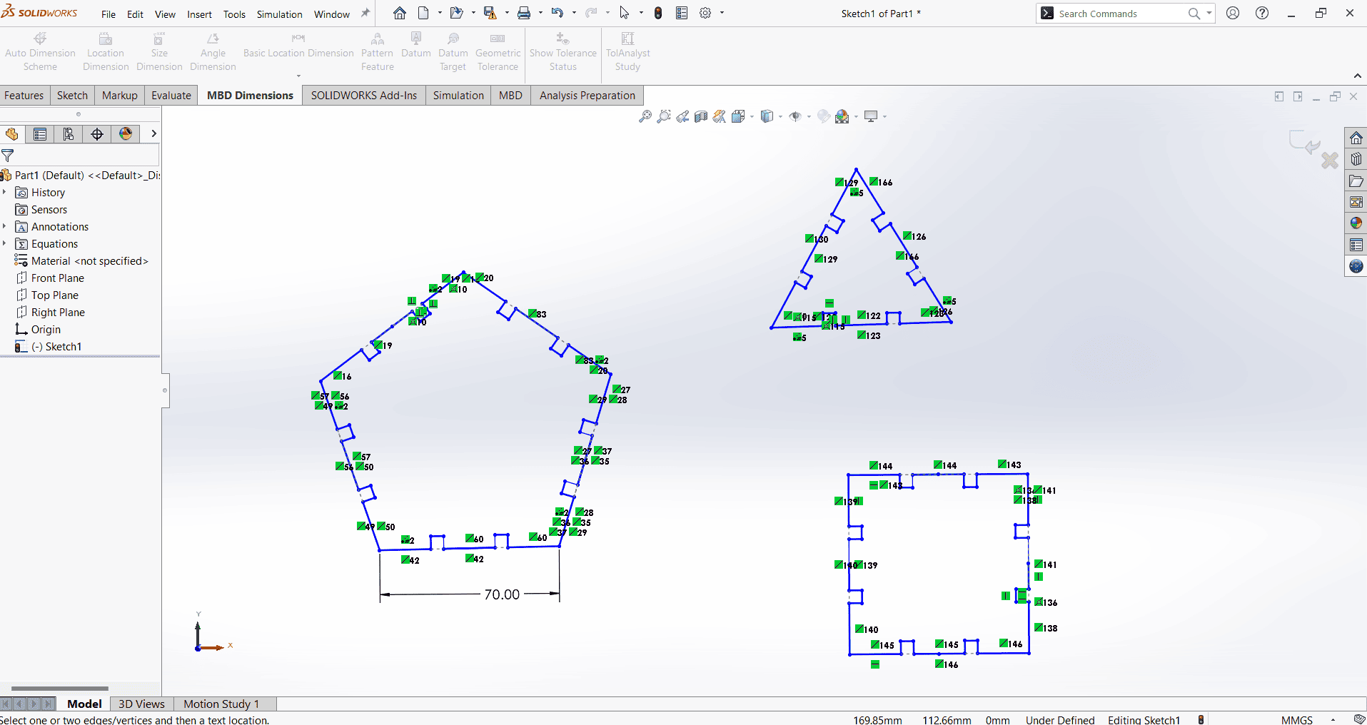
Next, I designed the part using parametric modeling. I selected the "Tools" option from the menu bar and navigated to the "Equations" section. Within this section, I defined a global variable named T, assigned it a value of 5mm, and added a comment labeling it as "Slot."
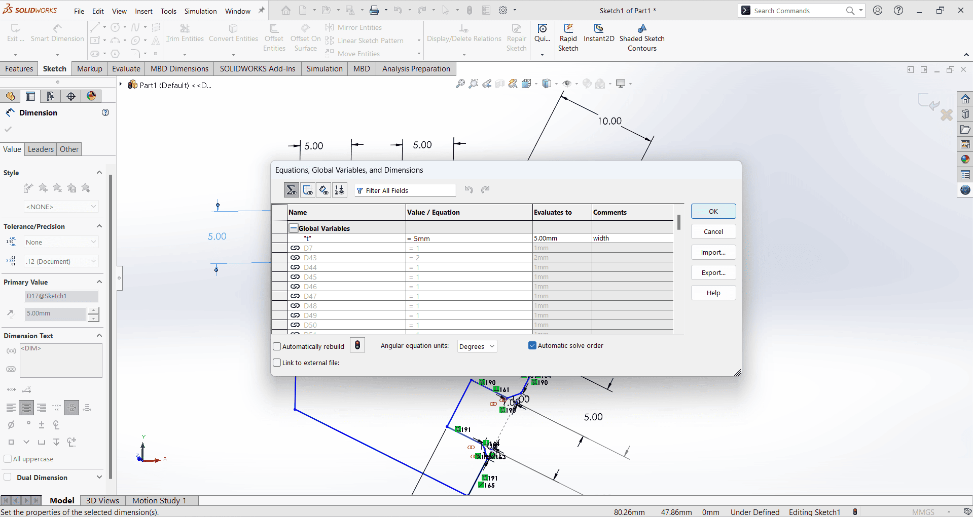
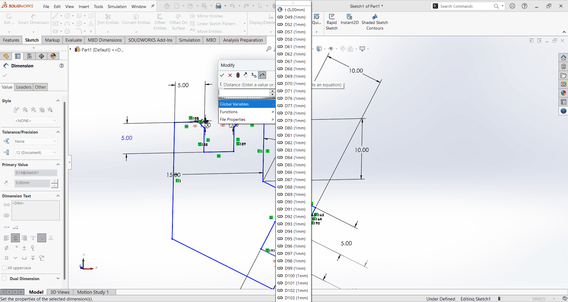
Next, I selected the Smart Dimension command to measure the actual dimensions of the slot. I then converted the measured dimensions into the global variable T, ensuring that all slots maintain uniform dimensions of 5mm × 5mm.
Next, I began developing the parts using SolidWorks 2D drawing. I created a square with dimensions of 50mm × 50mm, a pentagon with a size of 70mm × 70mm, and a triangle with the same dimensions of 70mm × 70mm.I then created a slot with dimensions of 5mm × 5mm in each shape.
It is essential to incorporate a chamfer for the proper fitting and easy removal of the part. Therefore, in this component, adding a chamfer is necessary. A 1mm chamfer should be applied to each joint section to ensure smooth assembly and disassembly.
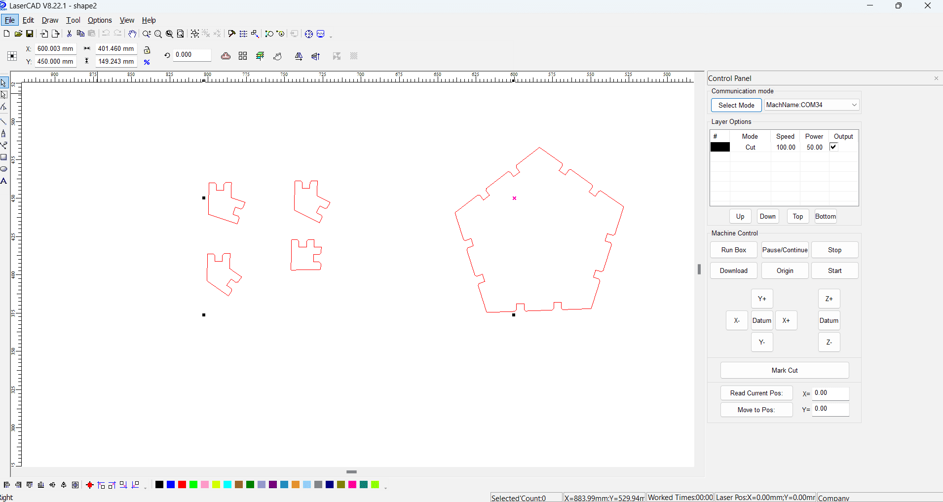
Once the part is ready for cutting, save the file in .DXF format. Then, open it in Laser CAD V8.22 software for laser cutting.
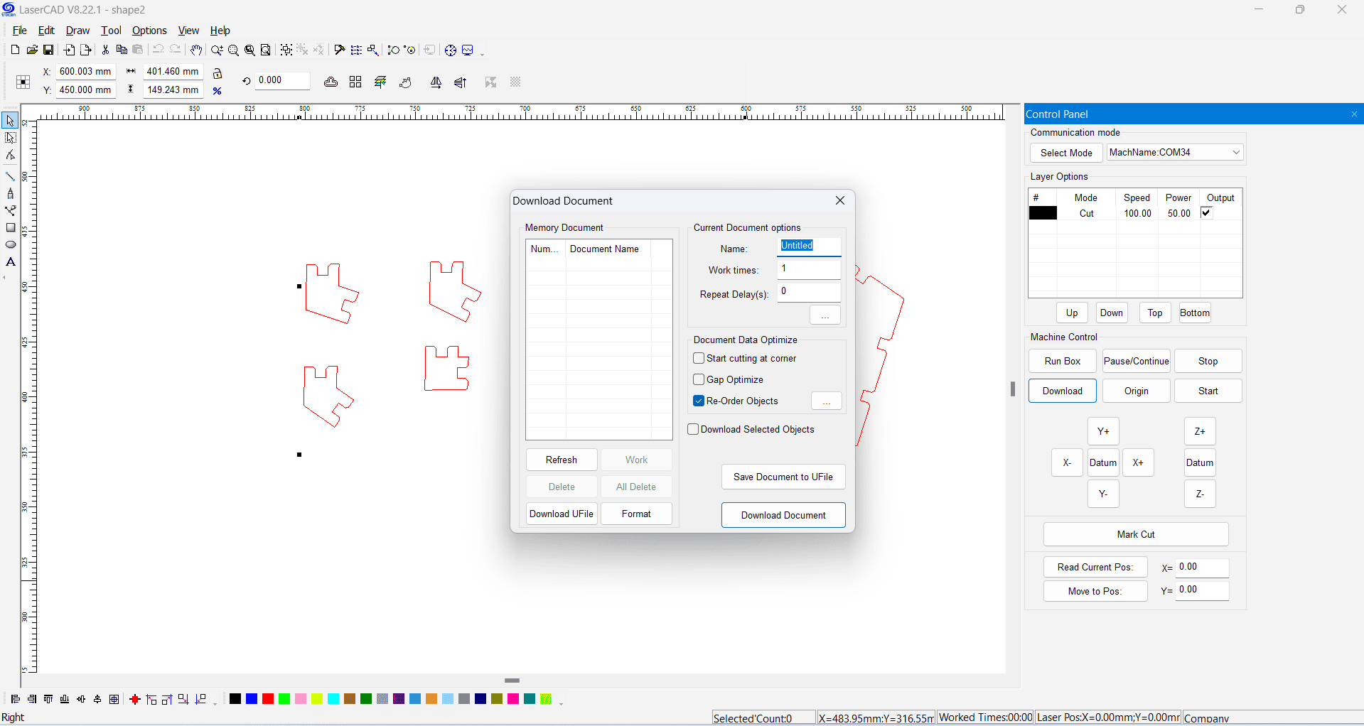
It is now time to proceed with the laser cutting machine to fabricate the part on cardboard. Power on the laser cutter and activate the cooling system. Place the material on the cutting bed and assign Black colors for cutting. Adjust the speed to 100 and the power to 50, then click Download in the control panel to initiate the process.
Open the Download Document menu in Laser CAD, review it carefully, and then click on the Download Document tab.
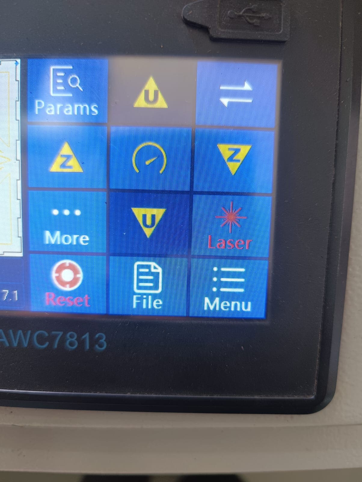
The image is then downloaded onto the laser cutting machine display. Adjust the laser pointer on the cutting material using the Up, Down, Left, and Right keys as required. Next, set the bed height to 6mm using the Up-Down keys in the program tab. Finally, set the origin by clicking the Origin button.
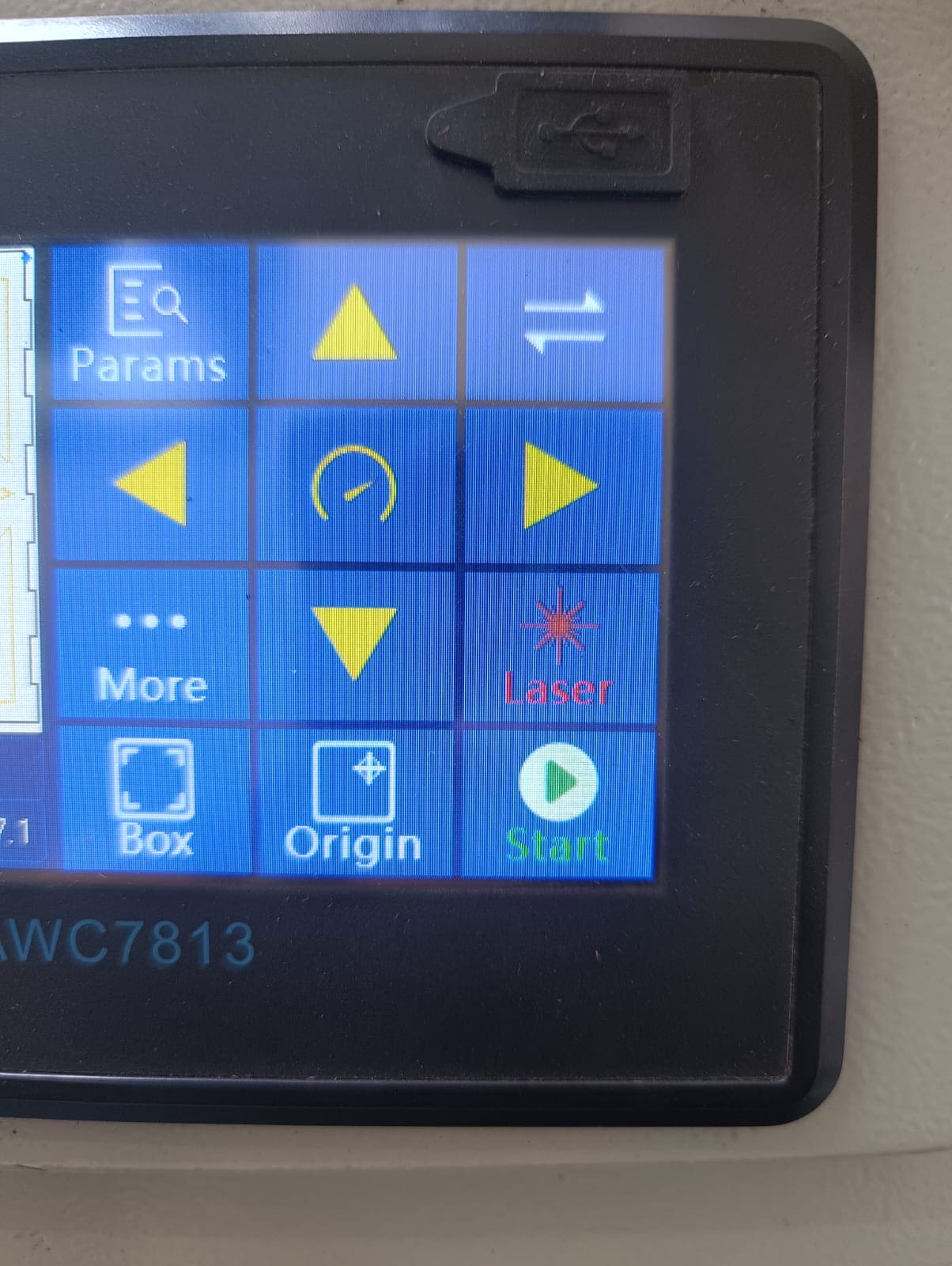
Then, press the start button to initiate the laser cutting process.

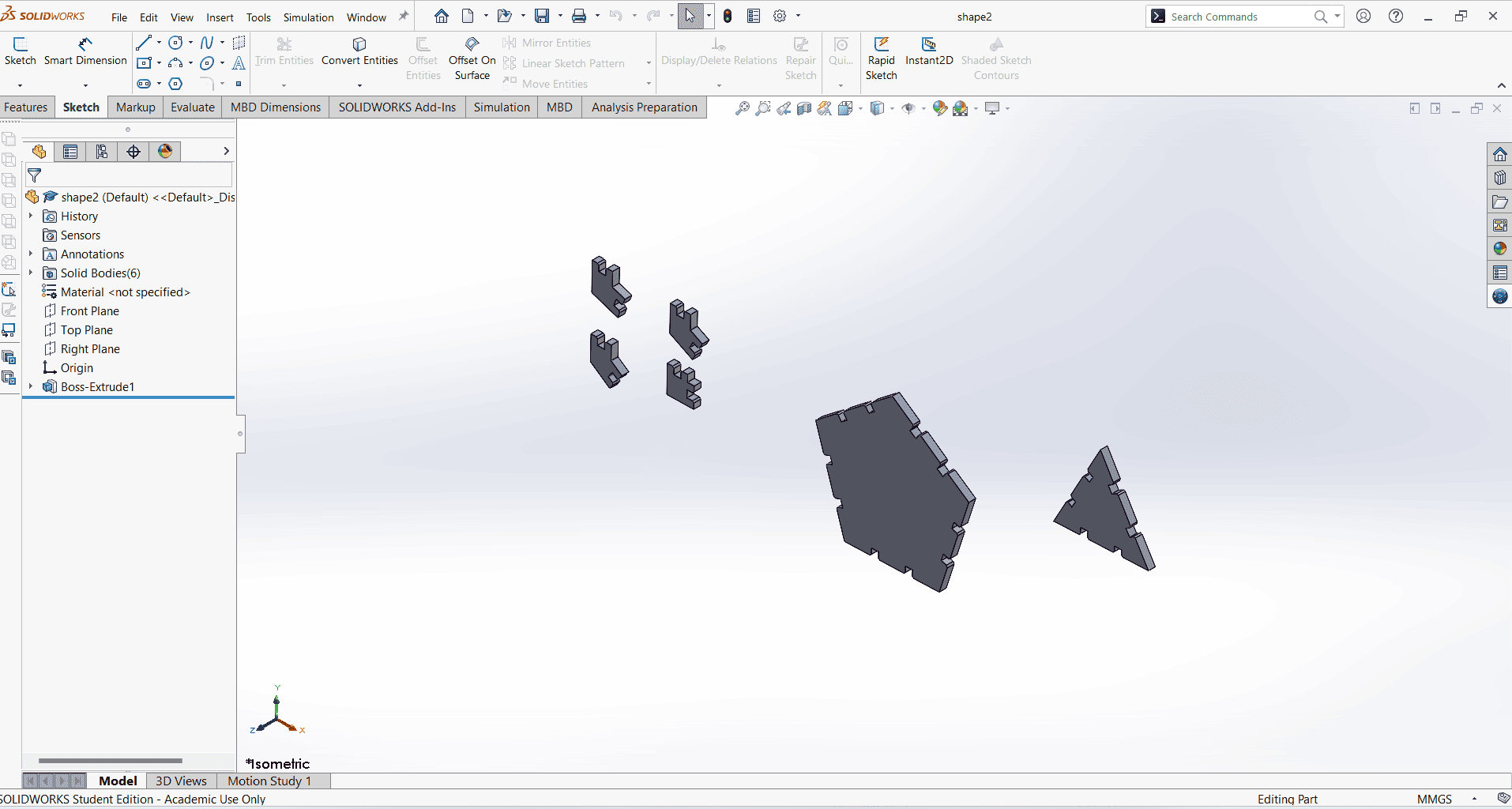
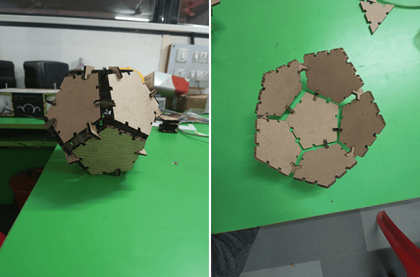
After cutting the pieces, they must be separated from the base and inspected to ensure proper functionality.
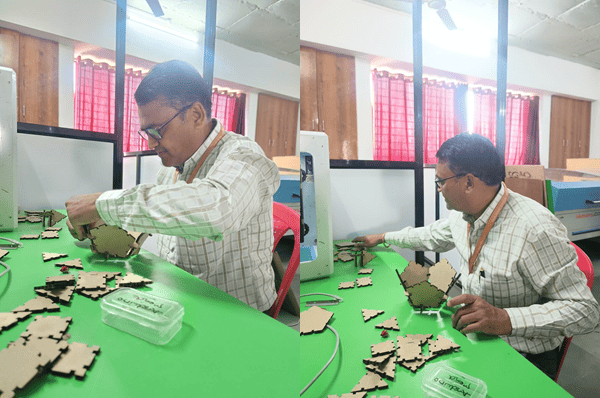
The next step is to assemble the pieces to form the desired shape.These are some of the shapes formed.
CUTTING ON VINYL CUTTER WITH INKSCAPE
I began by studying the instruction manual for the vinyl cutter in our lab. After gaining a thorough understanding, I proceeded with my cutting exercise.
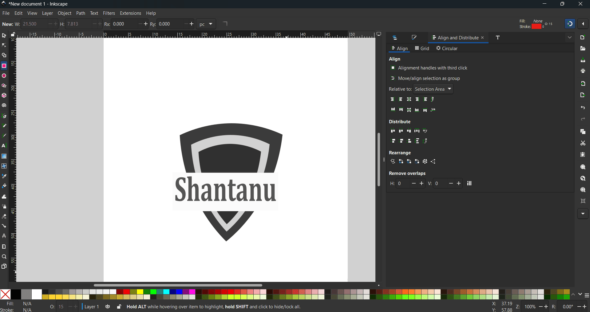
For my vinyl cutter assignment, it is essential to choose appropriate software for creating and editing vector graphics. I selected Inkscape, which I studied last week. I designed a simple logo featuring my name to paste to my laptop.
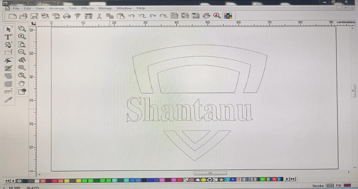
Save this image in .DXF format, then open it in FlexiSIGN software.
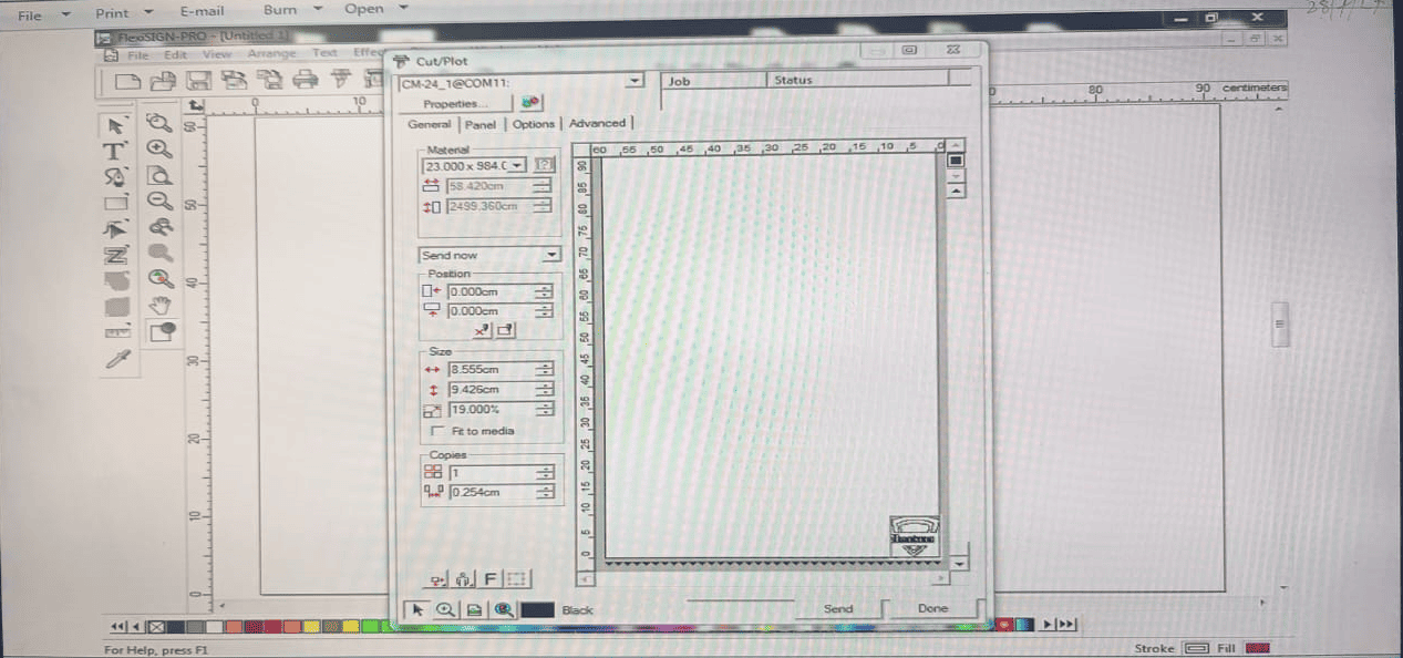
In the next step, open the Cut Plot application from the menu bar. Adjust the material settings, size, and number of copies as needed.
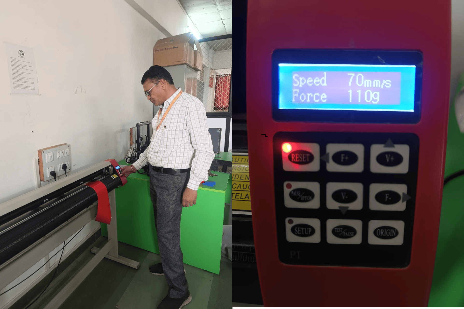
Next, proceed to the vinyl cutter and adjust the cutting force to 110g and the speed to 70 mm/s, depending on the vinyl thickness and the desired cut quality. Load the vinyl sheet onto the cutting plotter’s rollers, ensuring proper alignment. Use the F+ and F- buttons to position the cutter pointer, then press the Origin button to set the starting point.
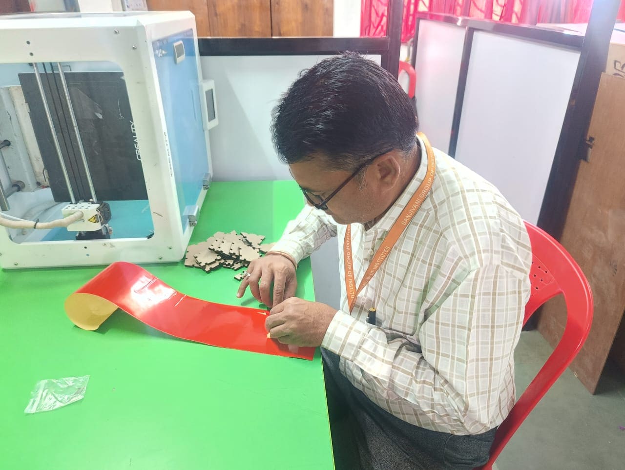
In the Cut Plot application within FlexiSIGN software, click Start to begin the cutting process. Once the cutting is complete, carefully remove the excess vinyl around the design using a cutter.
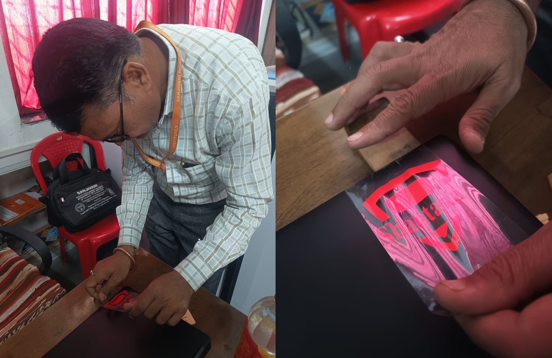
Place a sheet of transfer tape over the weeded vinyl design to ensure smooth and precise application.Position the vinyl on the desired surface and press it down firmly to ensure proper adhesion.
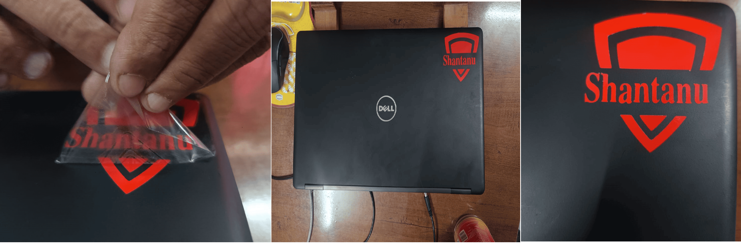
Slowly peel off the transfer tape, ensuring the vinyl design remains securely adhered to the surface.
Downloads
Laser Cutting Machine
Vinyl Cutter
Hero shot