Week 15
System Integration
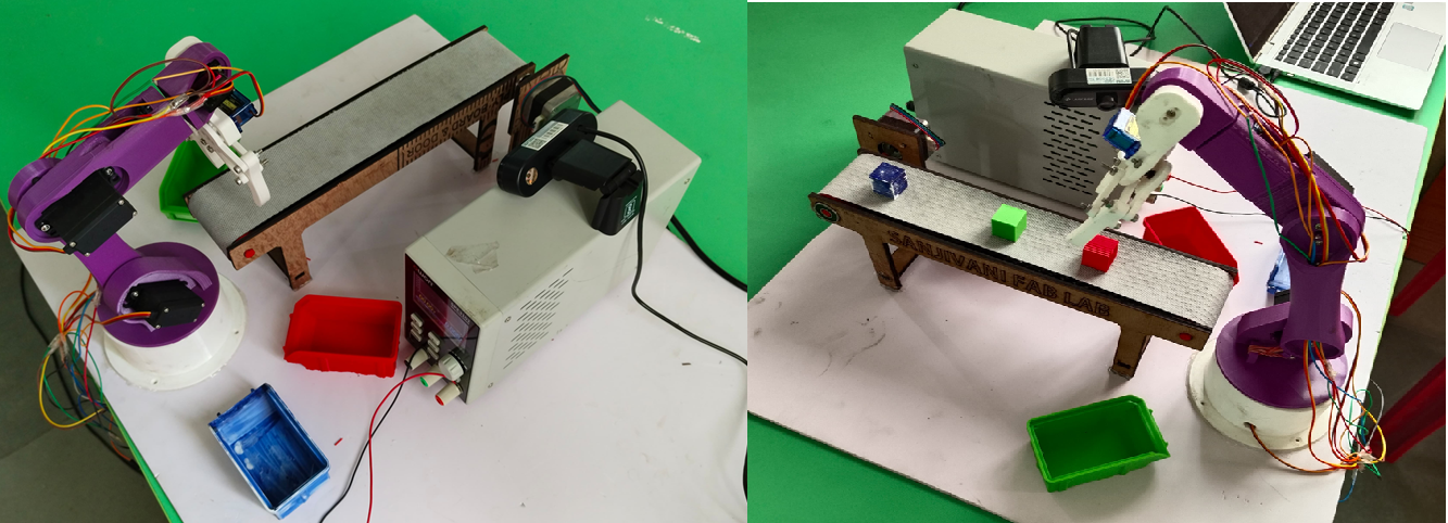
This week, The Color Sorting Robot is designed to detect, identify, and sort colored objects (e.g., red, green, blue) using a combination of sensors, actuators, and control logic. The system integrates hardware and software components to achieve autonomous operation.
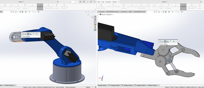
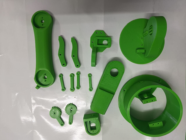
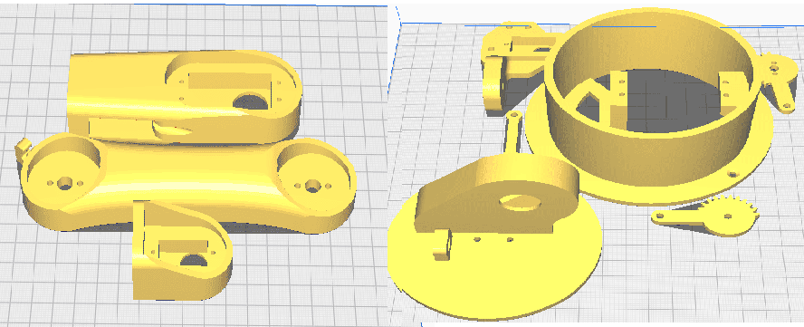
Mechanical Design and 3D Printing
A. Design Process
CAD Software Used: SolidWorks.
Design Parameters: Joint rotation angles, arm reach, payload capacity, base stability.
Parts Modeled:
1. Base Plate
2. Rotating Base
3. Shoulder, Elbow, and Wrist Links
3. Gripper Mechanism
4. Servo Mounts and Cable Paths
B. 3D Printing Specifications
Printer Type: FDM 3D Printer
Material Used: PLA
Layer Height: 0.2 mm
Infill Density: 20% depending on load
Supports: Enabled for overhangs and vertical joints
Print Orientation: Optimized to reduce support and improve streng
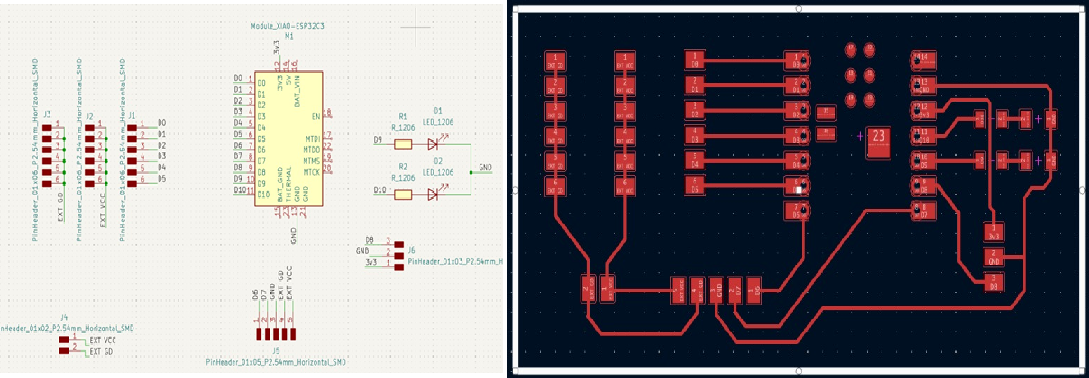
PCB Design Process
A. Design Software Used
EDA Tool: KiCad 7 (Free and open-source)
Library Used: Fab Library (from FabCloud GitLab)
B. Schematic Design
1. Components:
Microcontroller: XIAO ESP32-C3 (SMD footprint)
Servo Motor Header Pins (x3)
Conveyor DC Motor Driver Header
Power Input (Screw Terminal or JST)
Programming Header (optional USB-C / FTDI)
Color Sensor Connector (Header)
2. Routing:
Short, clean signal traces
Power traces with appropriate width
Decoupling capacitors near VCC-GND pins
C. Board Layout
Compact double-sided layout (if needed)
Mounting holes for frame integration
Clear silkscreen labels for ports
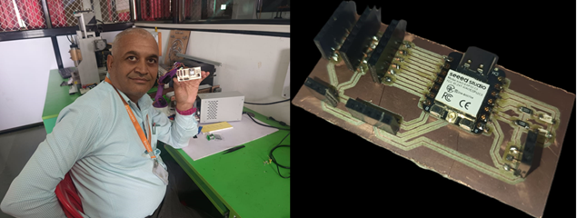
PCB Milling Process
A. Preparation
Design exported as SVG files
Toolpath generated using MODs CE
Milling Machine: CNC PCB mill
B. Tool Setup
Bit Used: 0.4–0.8 mm for traces, 1.0 mm for outline
Bed leveling and zeroing of X, Y, Z axes
Tape or fixture to secure copper board
C. Milling Steps
Trace milling (isolation paths)
Outline cutting
Cleaning and deburring
Visual inspection for broken traces
Soldering and Component Mounting
Components placed as per silkscreen and schematic
Soldered using fine-tipped soldering iron
Continuity test performed before powering
Components Mounted:
XIAO ESP32-C3
Female header for servo motor pins
Screw terminal for power
Pin header for color sensor connection
Smd LED
All headers are clearly marked for easy wiring
Common GND and 5V line distributed via copper traces
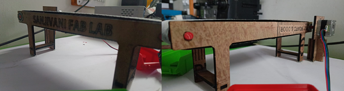
Conveyor Manufacturing
A. Design Process
The conveyor structure was designed using CAD software such as SolidWorks or Inkscape. The design included:
Side panels with precise slots for rollers and motor mounts
A base plate with cutouts for wiring, motor fitting, and electronics mounting
Tab-and-slot features for interlocking parts
Mounting slots for the color sensor and object guides
The design ensured accurate belt alignment, structural stability, and easy assembly.
B. Laser Cutting Process
The prepared CAD files were exported in DXF or SVG format. Laser cutting was carried out on 3 mm MDF or acrylic sheets using the following settings:
Cutting Power: 90%
Speed: 10 mm/s
Single Pass for Cuts
Separate layers were used for cutting and engraving, and materials were firmly fixed on the laser bed with safety precautions in place. The result was a clean and precise cut of all conveyor components.
C. Assembly Process
The laser-cut parts were cleaned and arranged.
Side panels were inserted into the base using the slot-tab mechanism.
Rollers were mounted using bearings or direct shaft holes on side panels.
A DC motor was fixed and aligned with one roller via a pulley or gear.
The conveyor belt was placed around the rollers with correct tension.
Additional brackets for sensors and guides were fixed in place.
Final adjustments were made, and the structure was tested for movement and stability.
Fixing the Motor and Wiring the System
A. Motor Mounting
To ensure reliable motion of the conveyor system, the DC motor was securely mounted in a designated slot on the laser-cut base plate:
A motor bracket was used to fix the motor to the MDF base using M3 screws and nuts.
The bracket position was aligned such that the motor shaft perfectly matched the roller or pulley.
Acrylic spacers were used if required to adjust the motor height and shaft alignment.
A pulley or gear was press-fitted or fixed with a set screw onto the motor shaft for driving the conveyor belt.
This mounting ensured vibration-free operation and stable torque transmission to the belt system.
B. System Wiring
All components were connected to the custom PCB or microcontroller (XIAO ESP32-C3) using neatly routed wires with labeled headers.
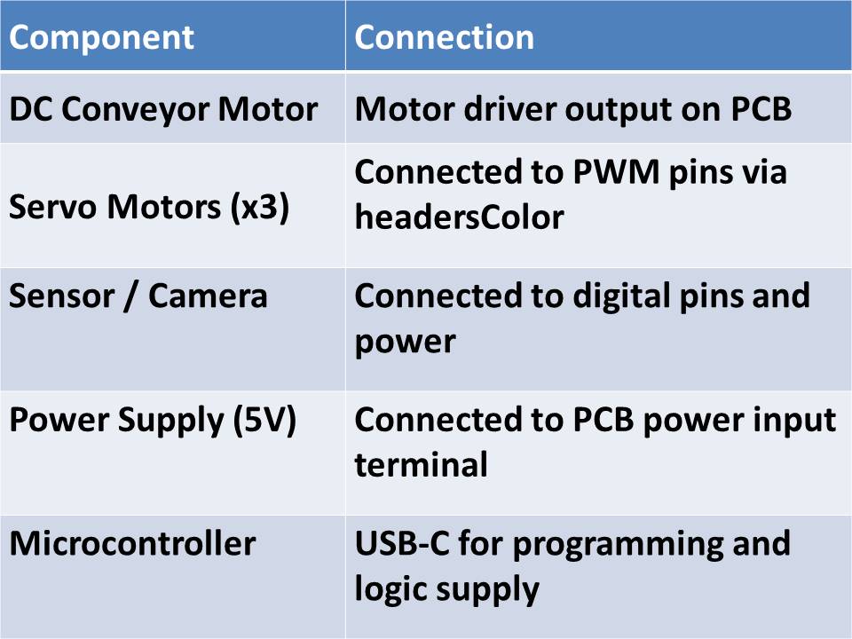
C. Wiring Practices:
All wires were cut to appropriate lengths to avoid clutter.
Heat-shrink tubing and female header connectors were used where needed.
Wires were fixed using cable ties and adhesive clips to maintain neat routing and prevent interference with moving parts.
A common GND line was maintained across all devices to ensure stable operation.
D. Final Checks:
After wiring, each connection was verified using a multimeter for continuity.
Power was applied using a regulated adapter, and individual components were tested.
The full system was run with the uploaded code to verify that the motor, servos, and color sensor operated as expected.
Programming for Color Sorting Robot
1. Arduino IDE Programming (Microcontroller Side)
The microcontroller used in this project is the XIAO ESP32-C3, programmed using the Arduino IDE. It controls:
The servo motors for sorting
The DC motor for the conveyor belt
Communication with the host system (PC with OpenCV)
Key Features of the Program:
Waits for color detection input (from OpenCV).
Based on the input (R, G, B), moves the respective servo.
Controls the conveyor belt motor using digital/analog pins.
2. Arduino Code (Servo + Motor Control):
#include < Servo.h >
Servo servo1, servo2, servo3, servo4, servo5, servo6;
void setup() {
Serial.begin(9600); // Initialize serial communication
Serial.println("System Initialized. Waiting for color input (1=Red, 2=Green, 3=Blue)...");
attachAllServos();
Serial.println("Moving to Home Position...");
moveToHome();
detachAllServos();
Serial.println("Servos detached. Ready for next operation.");
}
void loop() {
if (Serial.available() > 0) {
int colorInput = Serial.parseInt();
Serial.print("Received color code: ");
Serial.println(colorInput);
attachAllServos();
Serial.println("Moving to Home Position...");
moveToHome();
if (colorInput == 1) {
Serial.println("Picking object for RED...");
pickFromConveyor();
Serial.println("Placing object to RED drop zone...");
placeRed();
} else if (colorInput == 2) {
Serial.println("Picking object for GREEN...");
pickFromConveyor();
Serial.println("Placing object to GREEN drop zone...");
placeGreen();
} else if (colorInput == 3) {
Serial.println("Picking object for BLUE...");
pickFromConveyor();
Serial.println("Placing object to BLUE drop zone...");
placeBlue();
} else {
Serial.println("Invalid input received.");
}
Serial.println("Returning to Home Position...");
moveToHome();
detachAllServos();
Serial.println("Cycle Complete. Awaiting next input...");
}
}
// --------- Functions -----------
void attachAllServos() {
servo1.attach(3);
servo2.attach(5);
servo3.attach(6);
servo4.attach(9);
servo5.attach(10);
servo6.attach(11);
Serial.println("All servos attached.");
}
void detachAllServos() {
servo1.detach();
servo2.detach();
servo3.detach();
servo4.detach();
servo5.detach();
servo6.detach();
Serial.println("All servos detached.");
}
void moveToHome() {
servo1.write(120);
servo2.write(120);
servo3.write(160);
servo4.write(90);
servo5.write(60);
servo6.write(40);
delay(1000);
Serial.println("Moved to Home Position.");
}
void pickFromConveyor() {
servo1.write(120);
servo2.write(120);
servo3.write(130);
servo4.write(90);
servo5.write(60);
delay(1000);
servo6.write(0); // Close gripper
delay(1000);
Serial.println("Picked object from conveyor.");
}
void placeRed() {
servo3.write(160);
delay(1000);
servo1.write(60);
delay(1000);
servo3.write(130);
delay(1000);
servo6.write(40); // Open gripper
delay(1000);
servo3.write(160);
delay(1000);
Serial.println("Placed RED object.");
}
void placeGreen() {
servo3.write(160);
delay(1000);
servo1.write(0);
delay(1000);
servo3.write(130);
delay(1000);
servo6.write(40); // Open gripper
delay(1000);
servo3.write(160);
delay(1000);
Serial.println("Placed GREEN object.");
}
void placeBlue() {
servo3.write(160);
delay(1000);
servo1.write(180);
delay(1000);
servo3.write(130);
delay(1000);
servo6.write(40); // Open gripper
delay(1000);
servo3.write(160);
delay(1000);
Serial.println("Placed BLUE object.");
}
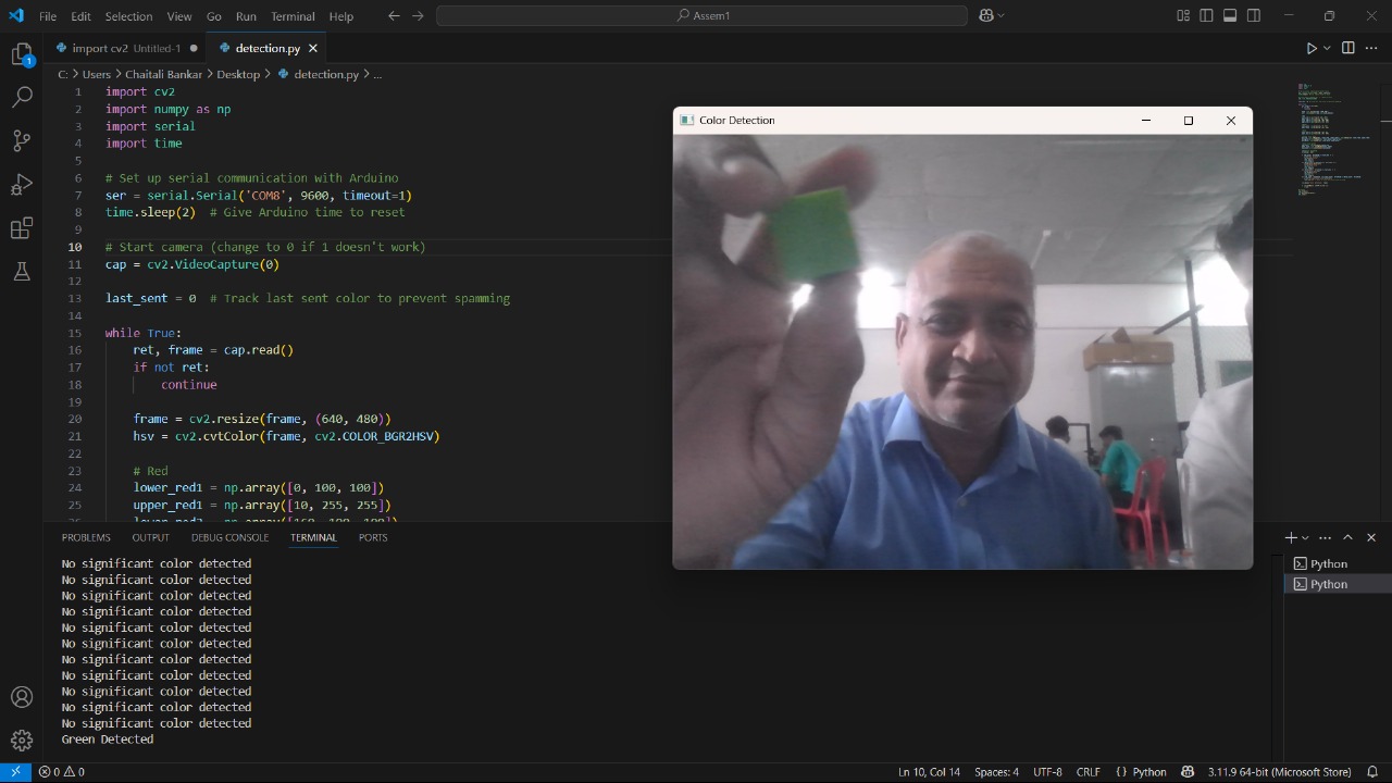
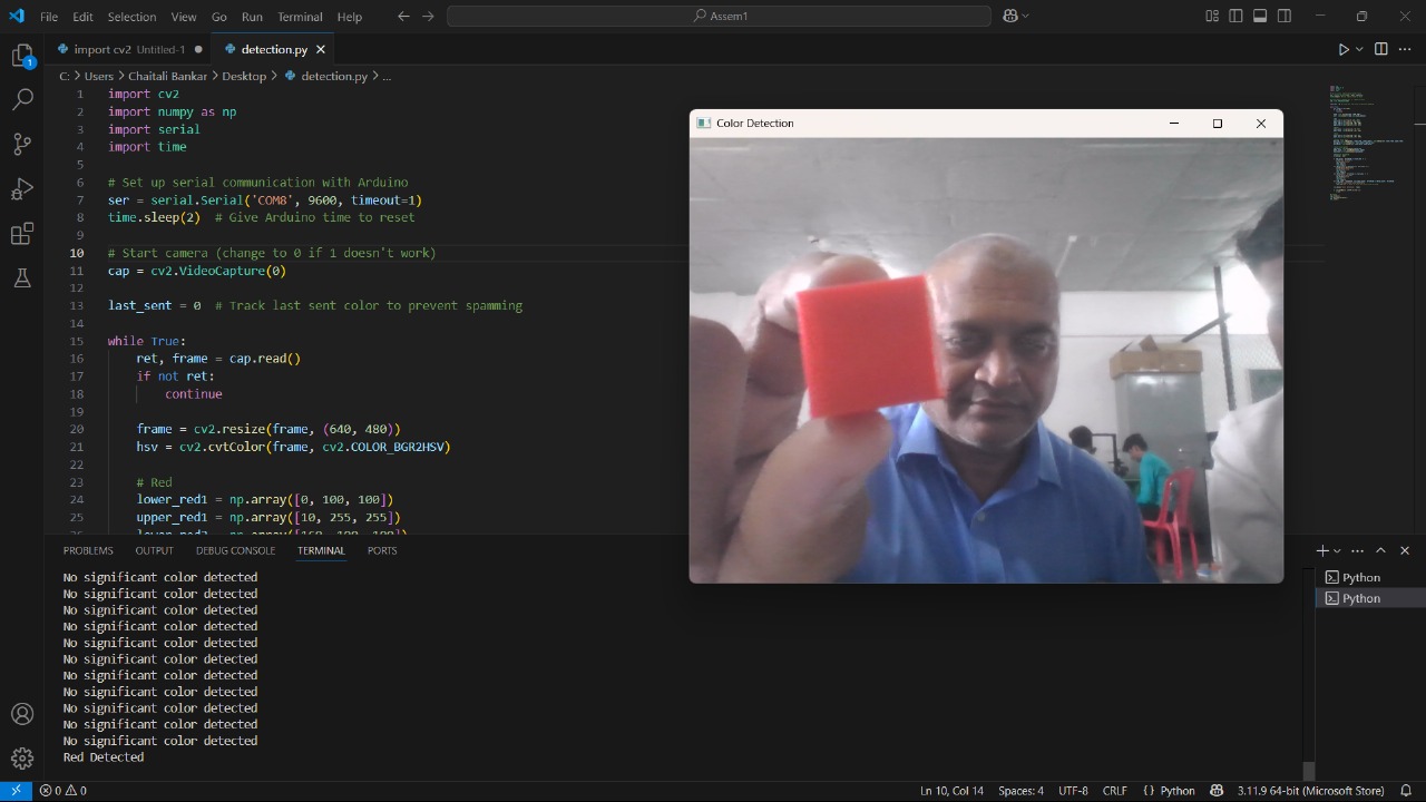
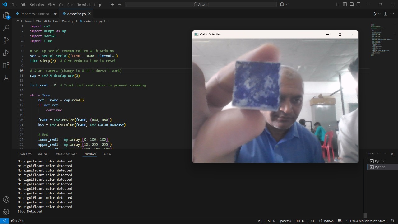
3. OpenCV Programming (Color Detection on PC)
The color sensor is implemented using a webcam and processed in real-time using Python with OpenCV.
Key Features of the Program:
Captures live video from webcam.
Detects object color (Red, Green, or Blue) in the region of interest (ROI).
Sends corresponding character (R, G, B) via serial to ESP32-C3.
4. Python OpenCV Code:
import cv2
import numpy as np
import serial
import time
# Set up serial communication with Arduino
ser = serial.Serial('COM8', 9600, timeout=1)
time.sleep(2) # Give Arduino time to reset
# Start camera (change to 0 if 1 doesn't work)
cap = cv2.VideoCapture(0)
last_sent = 0 # Track last sent color to prevent spamming
while True:
ret, frame = cap.read()
if not ret:
continue
frame = cv2.resize(frame, (640, 480))
hsv = cv2.cvtColor(frame, cv2.COLOR_BGR2HSV)
# Red
lower_red1 = np.array([0, 100, 100])
upper_red1 = np.array([10, 255, 255])
lower_red2 = np.array([160, 100, 100])
upper_red2 = np.array([179, 255, 255])
# Green
lower_green = np.array([40, 70, 70])
upper_green = np.array([80, 255, 255])
# Blue
lower_blue = np.array([100, 150, 0])
upper_blue = np.array([140, 255, 255])
# Create color masks
mask_red = cv2.inRange(hsv, lower_red1, upper_red1) + cv2.inRange(hsv, lower_red2, upper_red2)
mask_green = cv2.inRange(hsv, lower_green, upper_green)
mask_blue = cv2.inRange(hsv, lower_blue, upper_blue)
# Count color pixels
red_count = cv2.countNonZero(mask_red)
green_count = cv2.countNonZero(mask_green)
blue_count = cv2.countNonZero(mask_blue)
# Detection threshold
threshold = 2000
if red_count > threshold and last_sent != 1:
print("Red Detected")
ser.write(b'1\n')
last_sent = 1
time.sleep(2)
elif green_count > threshold and last_sent != 2:
print("Green Detected")
ser.write(b'2\n')
last_sent = 2
time.sleep(2)
elif blue_count > threshold and last_sent != 3:
print("Blue Detected")
ser.write(b'3\n')
last_sent = 3
time.sleep(2)
elif red_count < threshold and green_count < threshold and blue_count < threshold:
print("No significant color detected")
last_sent = 0 # Reset to allow next valid color to send
cv2.imshow("Color Detection", frame)
if cv2.waitKey(1) & 0xFF == ord('q'):
break
# Cleanup
cap.release()
cv2.destroyAllWindows()
ser.close()