Week 11
Networking and Communications
Networking and communications are all about making electronic devices talk to each other. In a network, two or more devices share information using wired or wireless methods. This helps in building systems where different parts can work together, send data, or control each other.
In this week of Fab Academy, I learned how to connect microcontrollers using communication protocols like UART, I2C, and SPI. I also explored how devices can talk over a network, such as using Bluetooth or Wi-Fi. This is very useful when we want to create smart systems that exchange data, control machines, or connect to the internet.
Networking and communication play an important role in modern electronics, especially in IoT (Internet of Things) applications.
Networking and communication mean sharing information between two or more devices. This can be done using wires (like USB cables) or wirelessly (like Bluetooth or Wi-Fi).
In electronics, communication is needed when one board (like a microcontroller) wants to send or receive data from another board or device. This helps them work together as a system.
There are some basic ways devices talk to each other:
UART (Serial) –Sends data one bit at a time, very simple, like talking back and forth.
I2C –Uses two wires to connect many devices, like a group chat.
SPI –Fast way to connect a few devices, using more wires.
Wi-Fi –Wireless way to connect to the internet or local network.
Bluetooth –Wireless way to connect nearby devices.
These methods allow devices to share sensor data, send commands, or control other devices, which is very useful in projects like smart homes, robots, and IoT.
Group Assignment
Individual Assignment
Group Assignment
Dr. Sujit and I collaborated on the Fab Academy Week 11 group assignment, focusing on networking and communication. Our work revolved around exploring how devices interact and share information effectively. We delved into the principles behind connecting hardware components, such as microcontrollers and sensors, using protocols like I2C, SPI, and UART. Additionally, we examined the role of wireless communication technologies, including Wi-Fi and Bluetooth, in enabling seamless data exchange.
>Together, we applied these concepts to practical tasks, such as creating setups where multiple devices communicate to achieve specific goals. This assignment not only strengthened our technical skills but also enhanced our understanding of how networking forms the backbone of modern technology.
The group assignment is linked here
Individual Assignment
In this assignment, I worked on designing, building, and connecting nodes using both wired and wireless communication methods. The goal was to set up a system where multiple devices could communicate effectively, each with unique network or bus addresses, and interact with local input or output devices.
The goal of this assignment is to design, build, and connect one or more nodes capable of communicating through wired or wireless networks using bus addresses and local input or output devices. This involves exploring different methods of communication, such as using protocols like I²C or UART for wired connections, and Bluetooth or Wi-Fi for wireless connectivity. Each node can be assigned a unique address and connected to input devices like sensors or output devices such as LEDs or buzzers. The assignment demonstrates how devices can exchange data over a network, respond to specific instructions, and perform tasks based on user inputs or sensor readings. Through this project, the differences between wired and wireless communication—such as speed, range, power consumption, and complexity—can be observed and compared, helping to understand how networked systems function in embedded electronics.
Wireless Comunication
As part of my individual assignment, I conducted a brief exploration of both wired and wireless communication technologies commonly used in embedded systems. In the domain of wireless communication, I focused specifically on Wi-Fi and Bluetooth, two widely adopted protocols that offer distinct advantages depending on the application. Wi-Fi enables high-speed data transmission over longer ranges, making it ideal for cloud-connected and IoT-based solutions, while Bluetooth offers low-power, short-range connectivity, which is well-suited for personal devices and sensor networks. By understanding the principles and use cases of these technologies, I gained insight into how wireless communication can be effectively integrated into embedded systems to enhance functionality, flexibility, and user experience.
Wireless bluetooth Comunication
In the case of Bluetooth wireless communication, I initially selected the DHT11 temperature and humidity sensor for programming and data transmission. The DHT11 is a commonly used digital sensor known for its simplicity and reliability in measuring environmental parameters. By interfacing the sensor with a microcontroller and configuring Bluetooth communication, I was able to transmit real-time temperature and humidity data wirelessly to a paired device. For this implementation, I utilized the custom PCB board I manufactured in Week 10, which integrates the XIAO ESP32-C3 microcontroller. This setup allowed for a compact and efficient hardware solution, further enhancing the reliability of the system. The overall process provided valuable hands-on experience in integrating sensor data acquisition with Bluetooth protocols, highlighting the efficiency of short-range wireless communication in low-power embedded applications.
In this case, I used the DHT11 temperature and humidity sensor, the XIAO ESP32-C3 microcontroller, and a mobile device as the output interface. The sensor was connected to the microcontroller, which processed the data and transmitted it via Bluetooth to a paired mobile device. I wrote the program for this system using the Arduino IDE, which provided a flexible and user-friendly environment for developing and uploading the code to the microcontroller. To visualize the data, I used the nRF Connect mobile application, which allowed me to receive and display real-time temperature and humidity readings transmitted from the ESP32-C3. This setup enabled efficient monitoring directly on the mobile phone.
Program Code for DHT11 Temperature and Humidity Sensor
#include < Arduino.h >
#include < DHT.h>
#include < BLEDevice.h>
#include < BLEServer.h>
#include < BLEUtils.h>
#include < BLE2902.h>
// DHT11 setup
#define DHTPIN D2 // GPIO2
#define DHTTYPE DHT11
DHT dht(DHTPIN, DHTTYPE);
// BLE setup
#define SERVICE_UUID "91bad492-b950-4226-aa2b-4ede9fa42f59"
#define CHARACTERISTIC_UUID "cba1d466-344c-4be3-ab3f-189f80dd7518"
BLECharacteristic *pCharacteristic;
bool deviceConnected = false;
class MyServerCallbacks: public BLEServerCallbacks {
void onConnect(BLEServer* pServer) {
deviceConnected = true;
void onDisconnect(BLEServer* pServer) {
deviceConnected = false;
}
};
void setup() {
Serial.begin(115200);
dht.begin();
// Initialize BLE
BLEDevice::init("XIAO_DHT11");
BLEServer *pServer = BLEDevice::createServer();
pServer->setCallbacks(new MyServerCallbacks());
BLEService *pService = pServer->createService(SERVICE_UUID);
pCharacteristic = pService->createCharacteristic(
CHARACTERISTIC_UUID,
BLECharacteristic::PROPERTY_READ |
BLECharacteristic::PROPERTY_NOTIFY
);
pCharacteristic->addDescriptor(new BLE2902());
pService->start();
BLEAdvertising *pAdvertising = BLEDevice::getAdvertising();
pAdvertising->start();
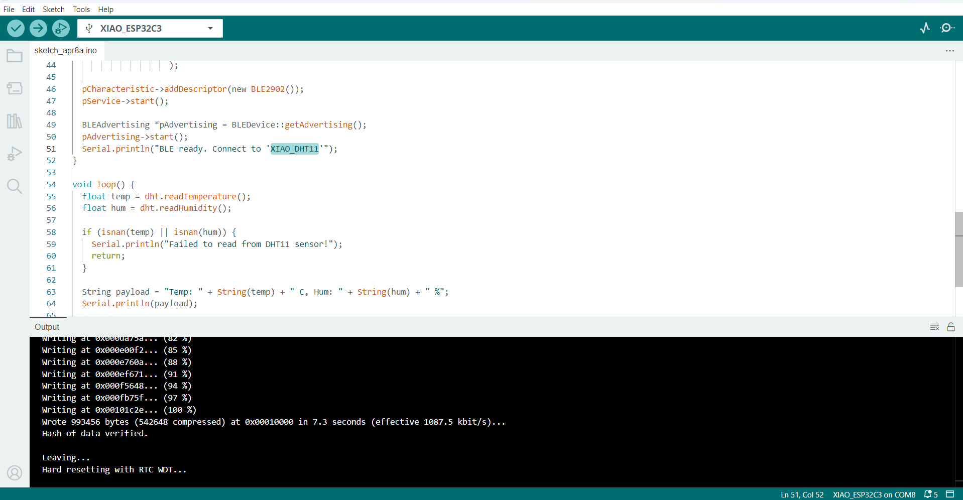
Serial.println("BLE ready. Connect to 'XIAO_DHT11'");
}
void loop() {
float temp = dht.readTemperature();
float hum = dht.readHumidity();
if (isnan(temp) || isnan(hum)) {
Serial.println("Failed to read from DHT11 sensor!");
return;
}
String payload = "Temp: " + String(temp) + " C, Hum: " + String(hum) + " %";
Serial.println(payload);
if (deviceConnected) {
pCharacteristic->setValue(payload.c_str());
pCharacteristic->notify();
}
delay(2000); // update every 2 seconds
}
I developed and uploaded the program using the Arduino IDE, which provided a convenient platform for writing and uploading the code.
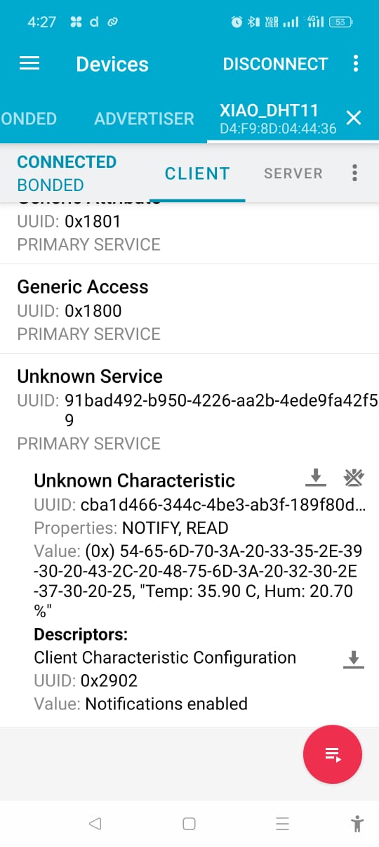
After successfully uploading the program to the microcontroller, I opened the nRF Connect mobile application and scanned for available Bluetooth devices. I located the device named XIAO_DHT11, and upon connecting to it, I navigated to Client > Unknown Services > Unknown Characteristics, where I was able to view the live temperature and humidity values being transmitted. This process effectively demonstrated real-time wireless data transfer using Bluetooth and allowed for seamless sensor data visualization through a mobile interface.
Secondly, I wrote a program for the ADXL345 accelerometer sensor, interfacing it with the XIAO ESP32-C3 microcontroller using the blue tooth protocol. In this phase of the project, I explored how to capture real-time acceleration data along the X, Y, and Z axes. The ADXL345 is a low-power, high-resolution, 3-axis digital accelerometer, ideal for motion and orientation sensing applications.
Program Code for ADXL345 Accelerometer Sensor
#include < Wire.h>
#include < Adafruit_Sensor.h>
#include < Adafruit_ADXL345_U.h>
#include < BLEDevice.h>
#include < BLEServer.h>
#include < BLEUtils.h>
#include < BLE2902.h>
// BLE Service & Characteristic UUIDs
#define SERVICE_UUID "4fafc201-1fb5-459e-8fcc-c5c9c331914b"
#define CHARACTERISTIC_UUID "beb5483e-36e1-4688-b7f5-ea07361b26a8"
// Accelerometer
Adafruit_ADXL345_Unified accel = Adafruit_ADXL345_Unified(12345);
// BLE stuff
BLECharacteristic *pCharacteristic;
bool deviceConnected = false;
class MyServerCallbacks : public BLEServerCallbacks {
void onConnect(BLEServer* pServer) {
deviceConnected = true;
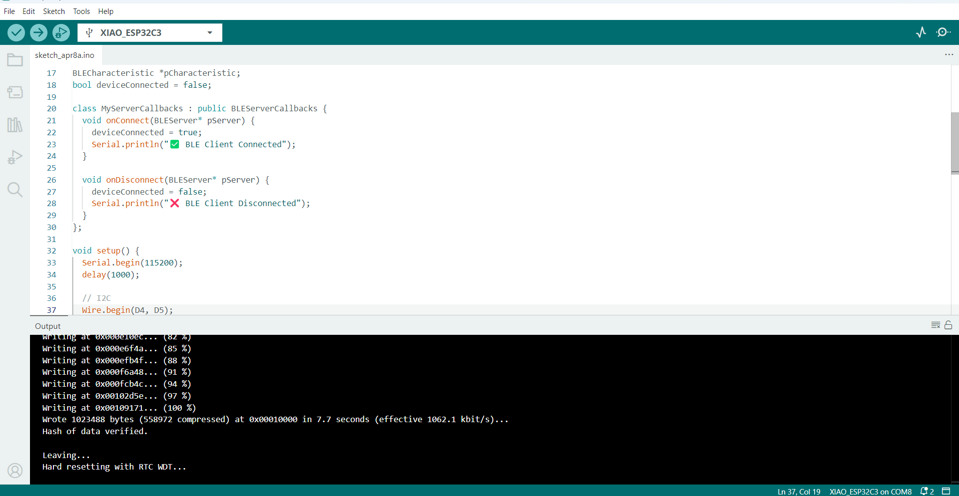
Serial.println("✅ BLE Client Connected");
}
void onDisconnect(BLEServer* pServer) {
deviceConnected = false;
Serial.println("❌ BLE Client Disconnected");
}
}
>void setup() {
Serial.begin(115200);
delay(1000);
// I2C
Wire.begin(D4, D5);
// Init ADXL345
if (!accel.begin()) {
Serial.println("❌ ADXL345 not found. Check wiring.");
while (1);
}
accel.setRange(ADXL345_RANGE_2_G);
Serial.println("✅ ADXL345 Ready");
// Init BLE
BLEDevice::init("XIAO_ADXL345");
BLEServer *pServer = BLEDevice::createServer();
pServer->setCallbacks(new MyServerCallbacks());
BLEService *pService = pServer->createService(SERVICE_UUID);
pCharacteristic = pService->createCharacteristic(
CHARACTERISTIC_UUID,
BLECharacteristic::PROPERTY_NOTIFY
);
pCharacteristic->addDescriptor(new BLE2902());
pService->start();
pServer->getAdvertising()->start();
Serial.println("🔵 BLE Ready - Waiting for connection...");
}
void loop() {
if (deviceConnected) {
sensors_event_t event;
accel.getEvent(&event);
char data[50];
snprintf(data, sizeof(data), "X: %.2f Y: %.2f Z: %.2f",
event.acceleration.x,
event.acceleration.y,
event.acceleration.z);
Serial.println(data);
pCharacteristic->setValue((uint8_t*)data, strlen(data));
pCharacteristic->notify(); // Send notification to client
delay(500); // Adjust refresh rate
}
}
I developed and uploaded the program using the Arduino IDE, which provided a convenient platform for writing and uploading the code.
After uploading the code, I used the nRF Connect mobile application to scan for available Bluetooth devices, located the XIAO_ADXL345 module, and connected to it. By navigating through Client > Unknown Services > Unknown Characteristics, I was able to view the live acceleration values transmitted over Bluetooth. This setup enabled wireless monitoring of motion data and demonstrated the effective use of the Bluetooth protocol in real-time sensor applications.
Wireless WI-FI Comunication
The DHT11 is a small sensor used to measure temperature and humidity. It is easy to use with microcontrollers like the XIAO ESP32-C3.
When we connect the DHT11 sensor to the XIAO ESP32-C3, we can read the temperature and humidity values. The ESP32-C3 has built-in Wi-Fi, so we can send the sensor data wirelessly over a Wi-Fi network.
This allows us to monitor temperature and humidity from a mobile phone or computer, using a web browser or app, without using wires.In this program, I used a computer and web browser to view the sensor readings.
Program Code for DHT11 Temperature and Humidity Sensor
#include < WiFi.h>
#include < DHT.h>
// ==== Wi-Fi Credentials ====
const char* ssid = "SMK";
const char* password = "12345678";
// ==== DHT11 Setup ====
#define DHTPIN D1
// DHT11 connected to GPIO 2
#define DHTTYPE DHT11
DHT dht(DHTPIN, DHTTYPE);
// ==== Start Web Server ====
WiFiServer server(80);
void setup() {
Serial.begin(115200);
delay(1000);
dht.begin();
// ==== Connect to Wi-Fi ====
Serial.print("Connecting to WiFi");
WiFi.begin(ssid, password);
while (WiFi.status() != WL_CONNECTED) {
delay(500);
Serial.print(".");
}
Serial.println("\n✅ WiFi Connected!");
Serial.print("🌐 IP Address: ");
Serial.println(WiFi.localIP());
server.begin(); // Start the server
}
void loop() {
WiFiClient client = server.available(); // Listen for incoming clients
if (client) {
Serial.println("\n🌐 New Client Connected");
String request = client.readStringUntil('\r');
Serial.println("Request: " + request);
client.flush();
float temp = dht.readTemperature();
float hum = dht.readHumidity();
if (isnan(temp) || isnan(hum)) {
Serial.println("⚠️ Failed to read from DHT11");
client.stop();
return;
}
// ==== Send HTML Response ====
client.println("HTTP/1.1 200 OK");
client.println("Content-Type: text/html");
client.println("Connection: close");
client.println();
client.println("< html>< head>< meta charset='UTF-8'>< title>DHT11 Sensor< body>");
client.println("< h2>< CENTER>XIAO ESP32-C3 + DHT11 Sensor < / h2>");
client.print("
< CENTER>Temperature: ");
client.print(temp);
client.println(" & deg; C< /p>");
client.print("< p>< b>Humidity:< /b> ");
client.print(hum);
client.println(" %< /p>");
client.println("< p>< i>Data updates when you refresh the page.< /i>< /p>");
client.println("");
delay(10); // short delay before disconnect
client.stop();
Serial.println("❌ Client Disconnected");
}}
Then I uploaded the program to the XIAO ESP32-C3 using the Arduino IDE software. After the program was successfully uploaded, it generated an IP address to access the data.
.png )
After the program was successfully uploaded, it generated an IP address (192.168.137.147) in the serial monitor when the Wi-Fi was connected. I entered this IP address in the Chrome browser to view the temperature and humidity data. To get real-time data, I refreshed the page.
.png )
This program is designed to interface the ADXL345 accelerometer sensor with the XIAO ESP32-C3 microcontroller using the I2C protocol. The primary objective of the system is to wirelessly transmit real-time acceleration data over a Wi-Fi network. The ADXL345 is a low-power, 3-axis accelerometer capable of measuring acceleration with high resolution (up to ±16g). When integrated with the Wi-Fi-enabled XIAO ESP32-C3, the sensor data can be monitored remotely, enabling applications such as motion detection, vibration monitoring, and gesture recognition in IoT systems.
Program Code for ADXL345 Accelerometer Sensor
#include < WiFi.h>
#include < Wire.h>
#include < Wire.h>
#include < Adafruit_Sensor.h>
#include < Adafruit_ADXL345_U.h>
// Wi-Fi credentials
const char* ssid = "SMK";
const char* password = "12345678";
// Accelerometer
Adafruit_ADXL345_Unified accel = Adafruit_ADXL345_Unified(12345);
// Web server
WiFiServer server(80);
void setup() {
Serial.begin(115200);
delay(1000);
// Start I2C
Wire.begin(D4, D5); // SDA = GPIO 4, SCL = GPIO 5
// Initialize ADXL345
if (!accel.begin()) {
Serial.println("❌ ADXL345 not found. Check wiring.");
while (1);
}
accel.setRange(ADXL345_RANGE_2_G); // ±2g range
Serial.println("✅ ADXL345 initialized");
// Connect to Wi-Fi
Serial.print("Connecting to WiFi");
WiFi.begin(ssid, password);
while (WiFi.status() != WL_CONNECTED) {
delay(500);
Serial.print(".");
}
Serial.println("\n✅ WiFi Connected!");
Serial.print("🌐 IP Address: ");
Serial.println(WiFi.localIP());
server.begin();
}
void loop() {
WiFiClient client = server.available();
if (client) {
Serial.println("\n🌐 New Client Connected");
String request = client.readStringUntil('\r');
Serial.println("Request: " + request);
client.flush();
sensors_event_t event;
accel.getEvent(&event);
float x = event.acceleration.x;
float y = event.acceleration.y;
float z = event.acceleration.z;
// Send HTTP Response
client.println("HTTP/1.1 200 OK");
client.println("Content-Type: text/html");
client.println("Connection: close");
client.println();
client.println("< html>< head>< title>ADXL345 Acceleration< body>");
client.println("< h2>XIAO ESP32-C3 + ADXL345 Acceleration Data< /h2>");
client.print("< p>< strong>X: ");
client.print(x);
client.println(" m/s²< /p>");
client.print("< p>< strong>Y: ");
client.print(y);
client.println(" m/s²< /p>");
client.print("< p>< strong>Z:< /strong> ");
client.print(z);
client.println(" m/s²< /p>");
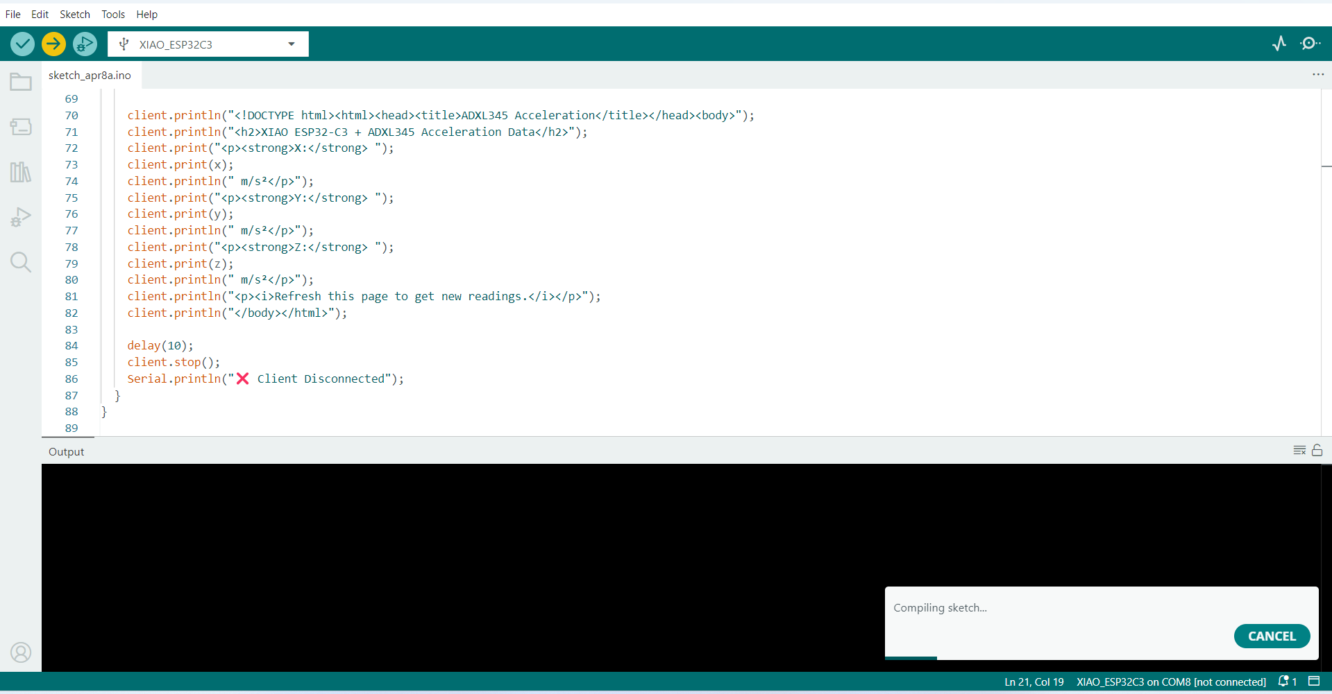
client.println("< p>< i>Refresh this page to get new readings.");
client.println("< /body>< /html>");
delay(10);
client.stop();
Serial.println("❌ Client Disconnected");
}
}
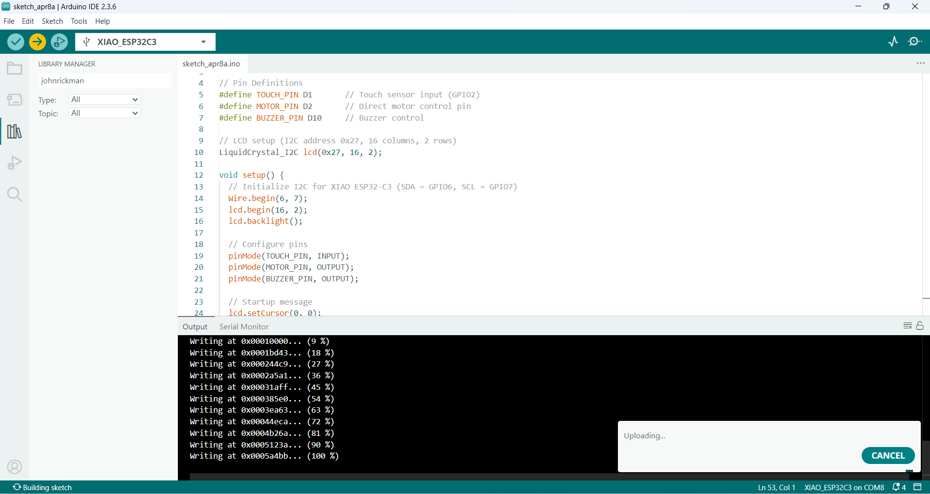
Then I uploaded the program to the XIAO ESP32-C3 using the Arduino IDE software.
After the program was successfully uploaded, it generated an IP address (192.168.137.185) in the serial monitor when the Wi-Fi was connected.
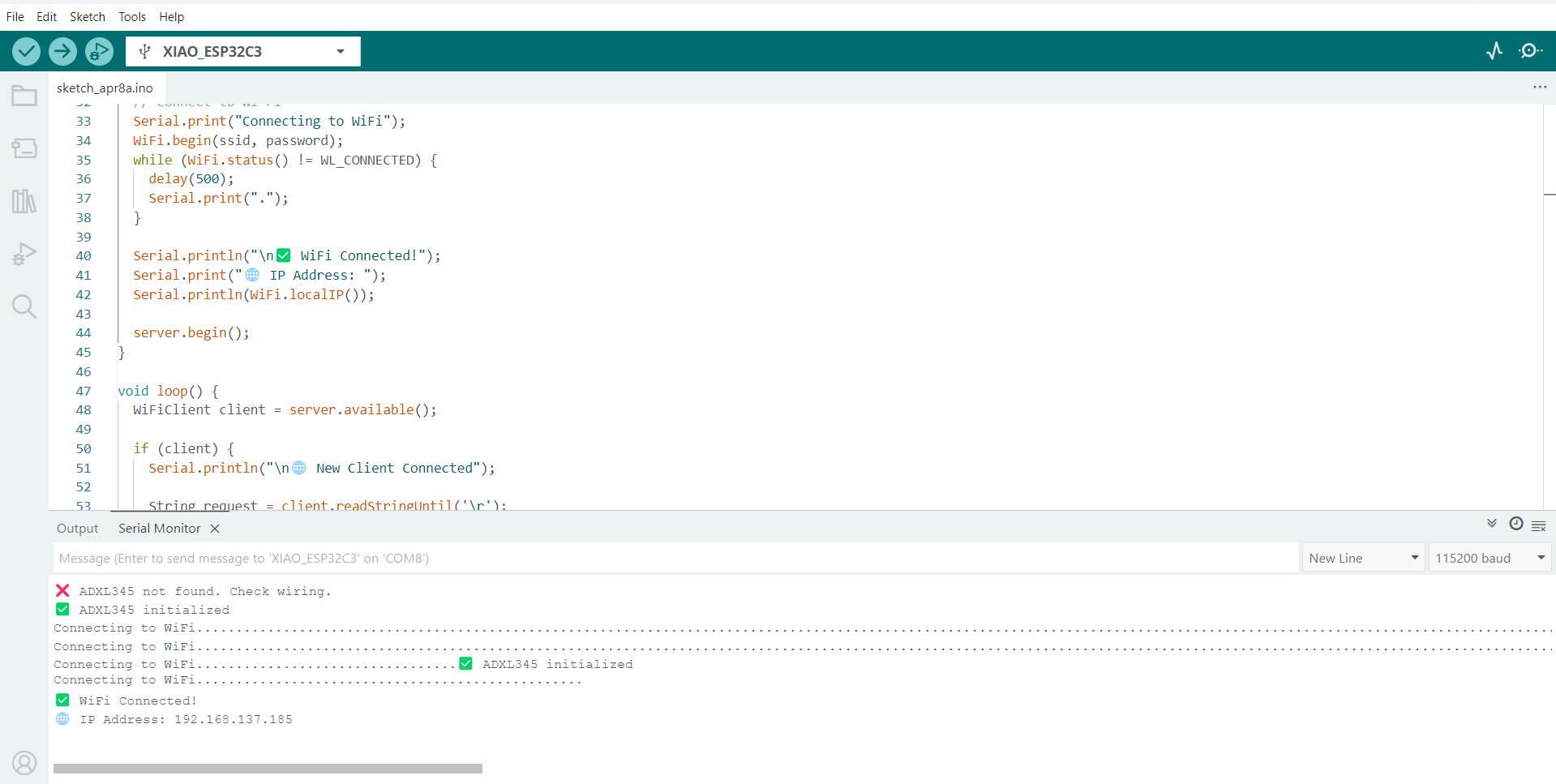
I entered this IP address in the Chrome browser to view the X, Y, and Z axis acceleration data. To get real-time updates.
Wire Comunication
A wire communication protocol is a method used by electronic devices to send and receive data through wires. It sets the rules for how devices like sensors and microcontrollers talk to each other. There are different types of wire communication protocols, such as I2C, SPI, and UART. I2C uses only two wires and allows many devices to share the same connection by giving each device a unique address. SPI is faster and uses four wires, but usually connects fewer devices. UART is a simple two-wire method used for one-to-one communication, like connecting to a serial monitor or Bluetooth. These protocols help devices share data correctly and work together in electronic projects.
For learning the I2C protocol, I used the XIAO ESP32-C3 board along with a 5V motor, a touch sensor, an I2C LiquidCrystal display, and a buzzer. The goal of this setup is to understand how components communicate using I2C and to control multiple devices based on a sensor input. When the touch sensor is touched, the serial monitor displays "Touch State: HIGH", the motor turns ON, the buzzer is activated, and the LCD screen shows the message "MOTOR ON". When the touch sensor is not touched, the serial monitor displays "Touch State: LOW", the motor turns OFF, the buzzer is deactivated, and the LCD displays "MOTOR OFF". This simple project helps in understanding how digital inputs can be used to control outputs while also using the I2C protocol to display real-time feedback.
Program Code for I2C protocol
#include < WiFi.h>
#include < LiquidCrystal_I2C.h>
// Pin Definitions
#define TOUCH_PIN D1 // Touch sensor input (GPIO2)
#define MOTOR_PIN D2 // Direct motor control pin
#define BUZZER_PIN D10 // Buzzer control
// LCD setup (I2C address 0x27, 16 columns, 2 rows)
LiquidCrystal_I2C lcd(0x27, 16, 2);
void setup() {
// Initialize I2C for XIAO ESP32-C3 (SDA = GPIO6, SCL = GPIO7)
Wire.begin(6, 7);
lcd.begin(16, 2);
lcd.backlight();
// Configure pins
pinMode(TOUCH_PIN, INPUT);
pinMode(MOTOR_PIN, OUTPUT);
pinMode(BUZZER_PIN, OUTPUT);
// Startup message
lcd.setCursor(0, 0);
lcd.print("System Ready");
delay(1000);
lcd.clear();
Serial.begin(115200);
}
void loop() {
int touchState = digitalRead(TOUCH_PIN); // Read touch sensor
Serial.print("Touch State: ");
Serial.println(touchState);
if (touchState == HIGH) { // Sensor touched
digitalWrite(MOTOR_PIN, HIGH); // Turn ON motor
digitalWrite(BUZZER_PIN, HIGH); // Turn ON buzzer
lcd.clear();
lcd.setCursor(0, 0);
lcd.print("MOTOR ON");
} else { // Not touched
digitalWrite(MOTOR_PIN, LOW); // Turn OFF motor
digitalWrite(BUZZER_PIN, LOW); // Turn OFF buzzer
lcd.clear();
lcd.setCursor(0, 0);
lcd.print("MOTOR OFF");
}
delay(200);
}
}
Then I uploaded the program to the XIAO ESP32-C3 using the Arduino IDE software.
After successfully testing the basic functionality of the touch sensor with the motor, buzzer, and I2C LCD, the next step is to enhance and expand the program. Once the program has been successfully uploaded to the XIAO ESP32-C3 board, the next step is to test and validate the system to ensure it behaves as expected.
Now, touch the touch sensor and observe the following:
The serial monitor should display: Touch State: HIGH
The motor should turn ON
The buzzer should activate
The LCD display should show: "MOTOR ON"
When the sensor is not touched:
The serial monitor should display: Touch State: LOW
The motor should turn OFF
The buzzer should be OFF
The LCD display should show: "MOTOR OFF"
Heroshot