Week 5
3D Scanning and Printing
3D scanning and printing are integral to additive manufacturing, one of the most widely used manufacturing processes in the world. This process involves adding material only where necessary, minimizing waste. Therefore, mastering these techniques is crucial for anyone looking to excel in the manufacturing industry
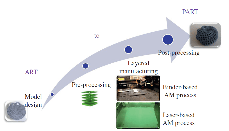
The definition of Additive Manufacturing (AM) varies among individuals, but the most straightforward and easily understandable definition is: Additive Manufacturing (AM) is a process in which digital 3D design data is used to construct a component layer by layer through material deposition.
This assignment documents my learning in 3D scanning and printing, covering topics such as the differences between additive and subtractive manufacturing processes, constraints and design rules for 3D printing, various materials and processes used in 3D printing, different types of 3D printers, software, and 3D scanning. Additionally, I have detailed my hands-on experience using a 3D printer and 3D scanner for both individual and group assignments, including successfully 3D printing my own scanned model.
As a longtime 3D printing hobbyist, I have always been passionate about this technology. Now, I am excited to apply it to fabricate parts for my final project. Furthermore, I have documented what went well, what challenges I encountered, how I would approach things differently in future assignments, and my overall learning outcomes.
In general, parts that are difficult to manufacture using conventional methods can be easily and efficiently produced with additive manufacturing. Manufacturing processes are broadly classified into two categories:
1. Additive Manufacturing
2. Subtractive Manufacturing
Understanding the differences between these two methods is essential for optimizing production efficiency and selecting the appropriate technique for a given application.
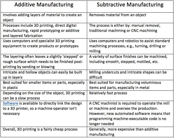
Difference between the Additive and Subtractive Manufacturing
3D Printing Processes
1. Photopolymerization
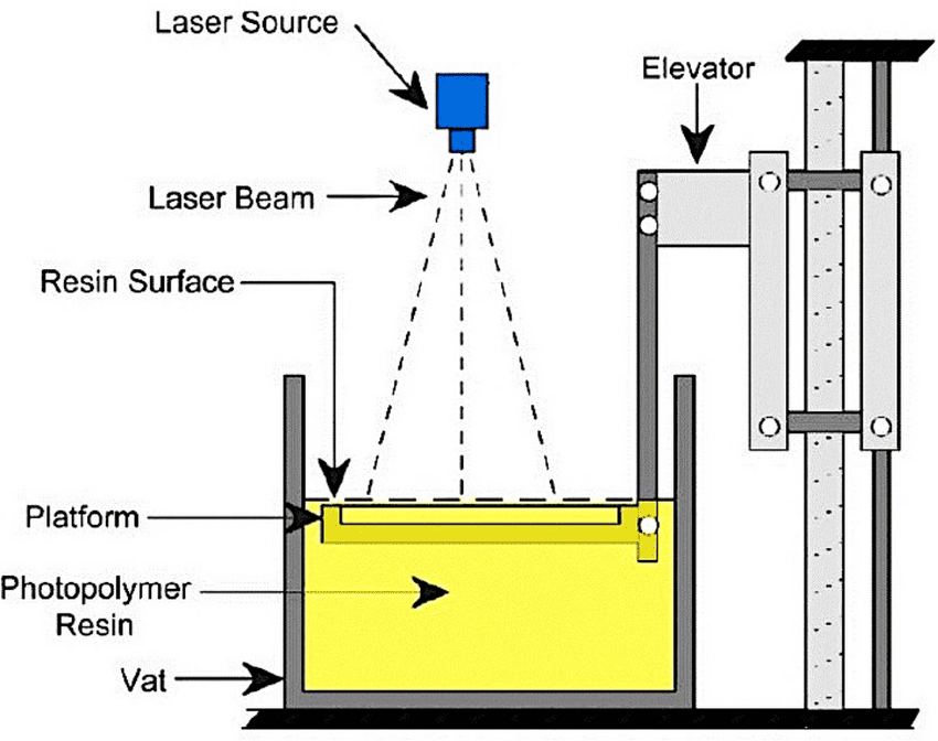
3D printing techniques, also known as additive manufacturing, rapid prototyping, or layered machining, were first developed in the 1980s to produce complex components without the need for molds or intricate machining processes. The advancements in polymer chemistry and its versatility have significantly enhanced the appeal of photopolymerization-based 3D printing techniques among polymer chemists, material scientists, and engineers.
Techniques such as stereolithography (SLA), digital light processing (DLP), and continuous liquid interface production (CLIP) are all 3D photopolymerization-based processes that enable the fabrication of multifunctional 3D material systems with controllable optical, chemical, and mechanical properties. These methods are particularly well-suited for achieving high resolution at low feature sizes, reaching the micrometer scale.
As a result, photopolymerization-based 3D printing has had a significant impact across various fields, including microfluidics, biomedical devices, soft robotics, surgery, tissue engineering, dentistry, and drug delivery.
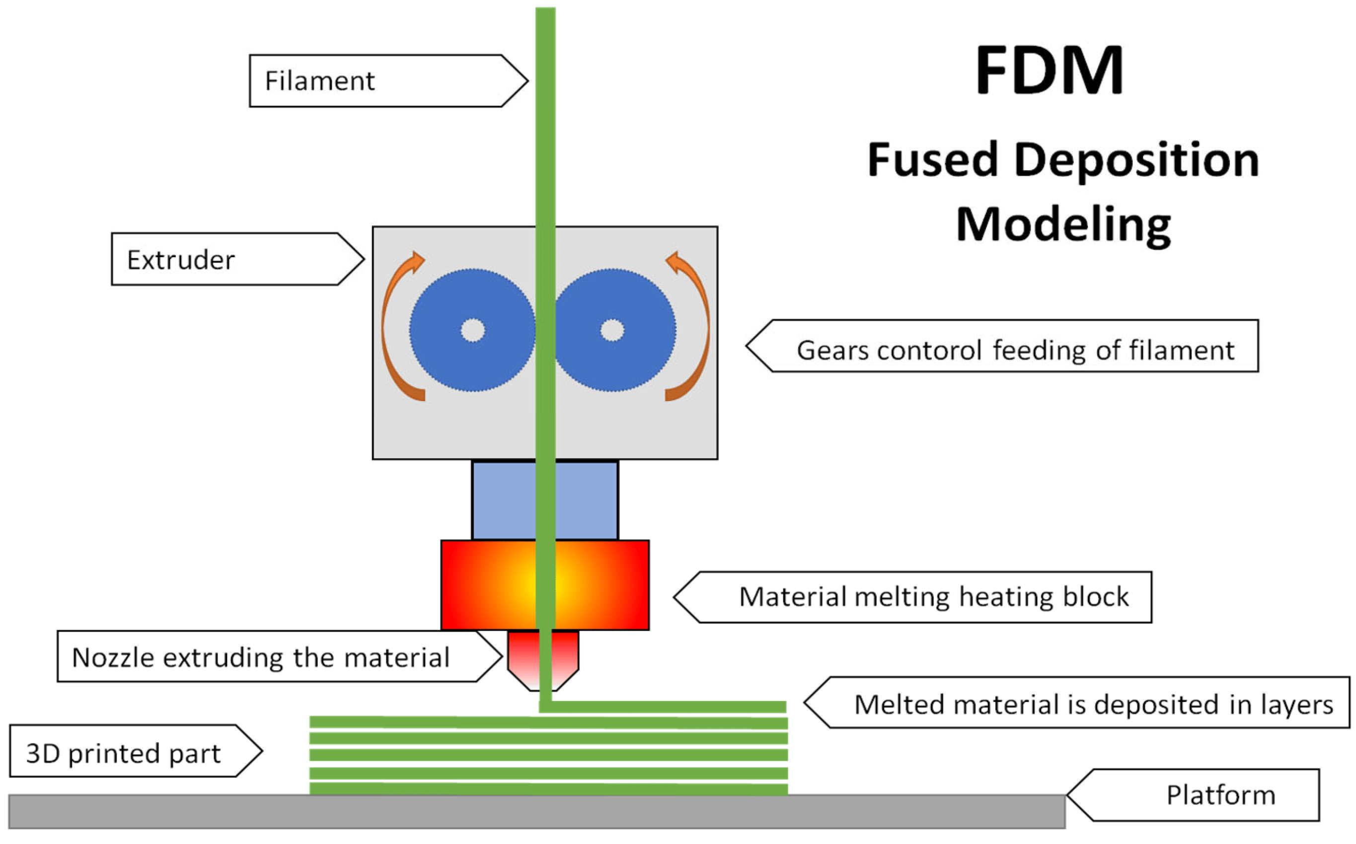
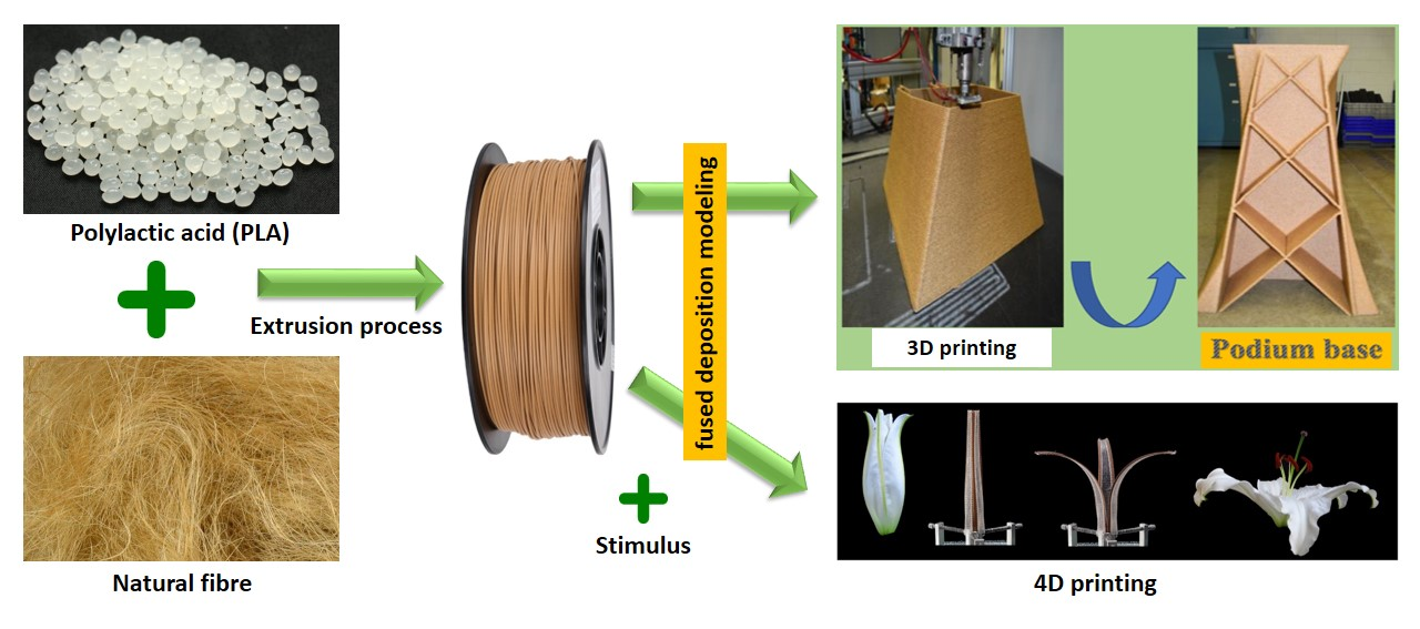
2. Fused Deposition Modeling (FDM)
Fused Deposition Modeling (FDM) is a widely used 3D printing technology that employs thermoplastic polymers to fabricate complex 3D objects. During the printing process, thermoplastic filaments are melted and extruded through a heated nozzle, then deposited in a semi-solid form onto a solid substrate. Commonly used thermoplastics, such as polycarbonate (PC), acrylonitrile butadiene styrene (ABS), and polylactic acid (PLA), typically have low melting points.
FDM method faces several challenges, including a limited selection of materials for filament preparation, degradation of material performance at elevated temperatures, high viscosity, low precision, and suboptimal surface quality.
For FDM-printed graphene-based 3D structures, two critical challenges are anisotropy and defect elimination. Precise control over printing parameters—such as printing speed, extrusion path, filament diameter, extrusion output, and printing temperature—along with optimized graphene loadings, significantly influences the performance of the final printed objects.
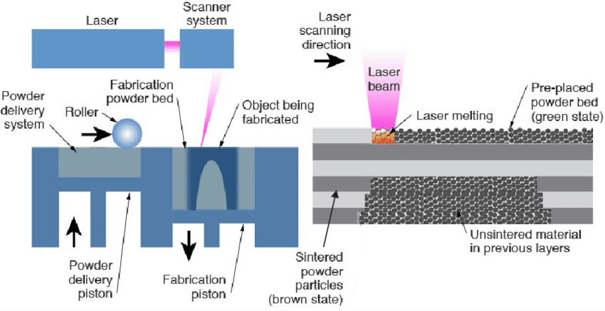
3. Powder Bed Fusion (PBF)
Powder Bed Fusion (PBF) is an additive manufacturing (AM) technique in which metal or polymer powders are selectively melted and fused layer by layer using an electron beam, laser beam, or binder. In this process, the final 3D prototype is created by rolling consecutive layers of powder onto the preceding layer, followed by selective fusion. Fine powders are evenly distributed and closely packed on the build platform, forming thin layers. Once printing is complete, the excess powder is removed, and additional post-processing steps, such as coating and infiltration, are performed on the final prototype.
One of the key advantages of Powder Bed Fusion is that the powder itself serves as a support structure, eliminating the need for separate support removal. However, this technique is costly and time-consuming due to the required post-processing. Additionally, when a binder is used for fusion, the resulting components may exhibit high porosity, leading to undesirable material properties.
A beetle-inspired honeycomb structure has been successfully fabricated using the Powder Bed Fusion technique, demonstrating its potential for producing intricate and biomimetic designs.
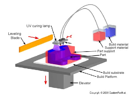
4. Material Jetting
Material Jetting is an additive manufacturing (AM) technique that creates objects using a process similar to a two-dimensional inkjet printer. Material is deposited onto a build platform using either a continuous or Drop-on-Demand (DOD) approach.
During the printing process, material is jetted onto the build surface, where it solidifies, forming the model layer by layer. Deposition occurs through a nozzle that moves horizontally across the build platform. The complexity of material jetting machines varies, as do their methods for controlling material deposition. Once deposited, the material layers are cured or hardened using ultraviolet (UV) light.
Due to the requirement for material deposition in droplet form, the range of usable materials is limited. Polymers and waxes are the most commonly used materials, as their viscosity and ability to form droplets make them well-suited for this process.
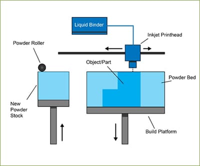
5. Binder Jetting
The Binder Jetting process utilizes two primary materials: a powder-based build material and a liquid binder. The binder serves as an adhesive, bonding the powder layers together during the printing process. A print head moves horizontally along the X and Y axes, depositing alternating layers of the build material and binder. After each layer is applied, the build platform is lowered, allowing the object to be formed layer by layer.
Due to the nature of the binding process, the material properties of binder-jetted parts are not always suitable for structural applications. Although Binder Jetting offers relatively high printing speeds, additional post-processing steps, such as infiltration or sintering, may be required, which can significantly extend the overall production time.
Similar to other powder-based additive manufacturing methods, Binder Jetting eliminates the need for support structures, as the printed object remains self-supported within the surrounding powder bed. Once printing is complete, the object is carefully extracted from the unbound powder. This technology is often referred to as 3DP technology, a term copyrighted under this name.
3D Printing Materials
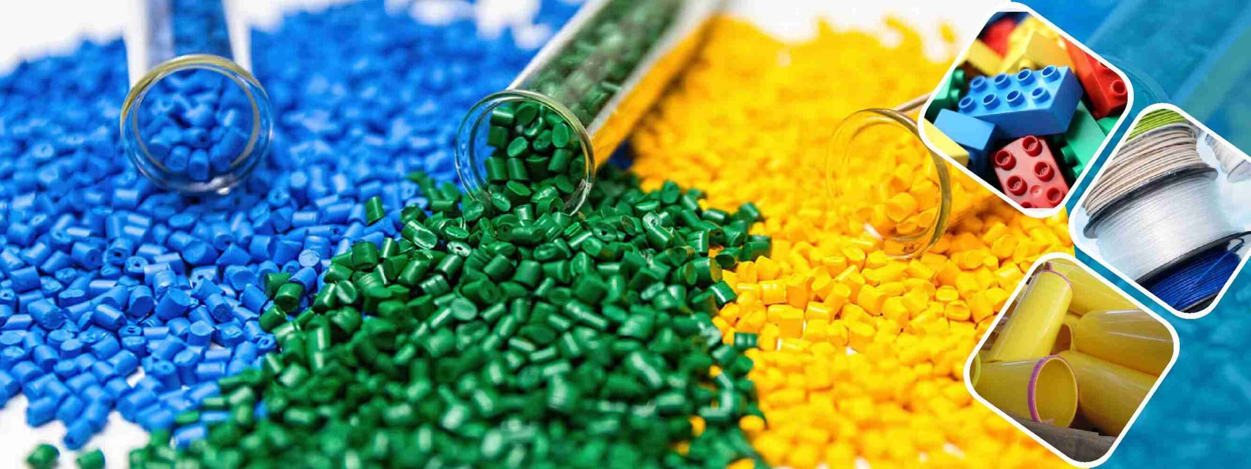
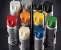
1. Plastic
Among the various raw materials used in 3D printing today, plastic is the most common. Its versatility makes it an ideal choice for producing a wide range of 3D-printed items, including toys, household fixtures, desk accessories, vases, and action figures. Plastic filaments are available in both transparent and vibrant colors, with red and lime green being particularly popular. These filaments are sold on spools and come in either a matte or glossy finish.
Plastic's widespread appeal can be attributed to its combination of firmness, flexibility, smooth texture, and extensive color options. Additionally, it is a cost-effective material, making it accessible to both creators and consumers. Most plastic products are manufactured using Fused Deposition Modeling (FDM) printers, where thermoplastic filaments are melted and deposited layer by layer to form the desired shape. The plastics used in this process are typically derived from one of the following materials:
Acrylonitrile Butadiene Styrene (ABS)
Acrylonitrile Butadiene Styrene (ABS) is a widely used thermoplastic, primarily available in filament form for Fused Deposition Modeling (FDM) 3D printing. It is also available in powder form for powder bed processes such as Selective Laser Sintering (SLS). ABS is one of the more accessible and cost-effective materials for 3D printing, with its popularity largely stemming from its long-established use in traditional manufacturing as additive manufacturing technology began to emerge.
ABS is a reusable material available in a wide range of colors, capable of producing durable, high-strength parts that can withstand elevated temperatures and be welded using chemical processes. However, it is not biodegradable and emits strong fumes during printing, necessitating the use of a closed 3D build chamber for safety. Additionally, ABS parts are prone to warping if the print bed is not heated during the printing process. Due to its strength and heat resistance, ABS is commonly used for manufacturing smaller components in automotive and electrical applications.
Polylactic Acid (PLA)
Polylactic Acid (PLA) offers several advantages, with its primary unique selling point (USP) being its biodegradability—unlike Acrylonitrile Butadiene Styrene (ABS).PLA is derived from renewable raw materials such as corn starch, making it an environmentally friendly option for 3D printing. It is widely used in desktop 3D printing due to its ease of use, though it has a slight tendency to shrink during printing. Unlike ABS, PLA does not require a heated print bed and prints at a lower temperature, typically ranging from 190°C to 230°C.
PLA is commonly utilized in the production of food packaging, biodegradable medical devices, and implants. Its ease of use, availability in various colors, and versatility as both a resin and filament make it an excellent material for 3D printing.
However, PLA has some limitations. It is more challenging to manipulate due to its rapid cooling and solidification. Additionally, it is less suitable for applications exposed to prolonged sunlight and is prone to deterioration when in contact with water.
Acrylic Styrene Acrylonitrile (ASA)
Acrylonitrile Styrene Acrylate (ASA) is a thermoplastic material with properties similar to Acrylonitrile Butadiene Styrene (ABS) but offers enhanced resistance to ultraviolet (UV) radiation, making it more suitable for outdoor applications. In addition to its excellent UV stability, ASA also provides strong temperature and impact resistance.
Like ABS, ASA should be printed on a heated bed platform to prevent warping. The printing parameters for ASA are generally similar to those used for ABS; however, extra precautions must be taken to ensure printing occurs within a fully enclosed chamber. This is necessary to contain potentially harmful styrene emissions released during the printing process.
Polyamides/Nylon
Polyamides, commonly known as nylon materials, are available in both fine white powder form—used in Powder Bed Fusion (PBF) technologies—and filament form for Fused Deposition Modeling (FDM).
Composed of semi-crystalline structures, polyamides offer an excellent balance of chemical and mechanical properties, including durability, toughness, impact resistance, and flexibility. These attributes make polyamide materials highly versatile, with applications spanning various industries, including industrial manufacturing, robotics, aerospace, automotive, and medical sectors.
Additionally, HP Multi Jet Fusion (MJF) technology utilizes a range of polyamides, providing the added benefit of industry-leading reusability, making it a sustainable and efficient choice for high-performance 3D printing.
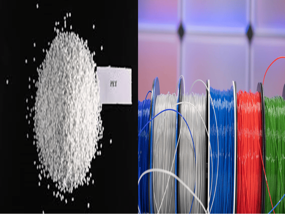
Polyethylene Terephthalate (PET)
Polyethylene Terephthalate (PET) is another widely used plastic in 3D printing, with applications ranging from thermoforming processes to blending with glass fibers to create high-performance engineering resins.
A commonly used variation in 3D printing is PETG (glycol-modified PET), which offers improved flexibility and ease of use compared to standard PET. This modification enhances its durability, making the printing process more efficient. PETG is widely utilized in the production of bottles due to its smooth surface and excellent water resistance.
For optimal 3D printing results, PETG should be printed at a temperature between 75°C and 90°C. It is often available as a translucent filament, similar to PETE and PETT. Additionally, PETG is known for producing minimal odors during the printing process, making it a user-friendly material for various applications.
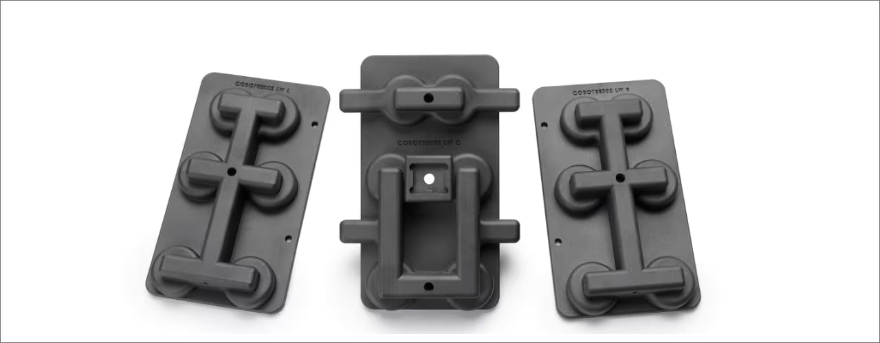
2. Powders
Printers that use Selective Laser Sintering (SLS) technology create the three-dimensional objects by melting and fusing together materials in powdered form. A high-powered laser is used to melt the powdered materials and form them into shapes. The high powered laser efficiently fuses each layer in succession, building pieces of the final object. The loose powder that is not used for printing fills the empty gaps as the 3D slicer is being used.
Polyamide 12 (PA 12)
Manufacturers like PA 12 as a general-purpose plastic because of its high impact strength, hardness, and resistance to weather and chemicals. The SLS 3D printed material flexes even more smoothly and doesn't break. Nevertheless, PA 12 does not offer a rough, matte surface for three-dimensional items.
Aluminum-Filled Nylon (Alumide)
This powdery substance is made by mixing aluminum dust with polyamide/nylon, as the name implies. Compared to other SLS 3D printing materials, alumide has a substantially higher density. In addition to giving the three-dimensional object a metallic appearance, it has remarkable thermal and conductive qualities.
Glass-Filled Nylon (PA-GF)
PA-GF is composed of 30% glass fiber and 70% nylon. PA-GF is not just a stiff powder but also possesses excellent mechanical strength. One of the most popular SLS 3D printing materials for creating applications and functional parts that need a higher degree of strength and stiffness is PA-GF because of its ability to withstand high temperatures and wear.
In the 3D printing process, a wide range of materials are used, depending on their specific applications and availability.
3. Resins
4. Metal
5. Metal Composite
6. Wood Composite
7. Carbon Fiber
8. Graphite and Graphene
9. Nitinol
10. Paper
Source and Credit for the 3D printing
Group Assignment
This week, we are learning about additive and subtractive manufacturing processes. We will use 3D printers to create objects that would otherwise be challenging to produce using subtractive methods. Additionally, we will explore the advantages of additive manufacturing, its various applications, and its impact on society.
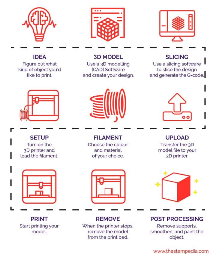
Process
1. Ideation
The first step before designing is ideation. This is where concepts and ideas take shape, forming the foundation for the design process.
Once the idea is established, it must be translated into a digital file. Various design software, such as AutoCAD,Solid Works and creo are available for this purpose. In this project, we will use solid work. Once the design is complete, it is saved in the . STL format, which is compatible with slicing software.
3. Slicing
Since a 3D printer prints objects layer by layer, the next step is slicing the model into layers. For this, we will use Ultimate CURA, a free slicing software. Ultimate CURA offers multiple settings that allow customization of the print, each serving a specific function to optimize the final output.
4. Uploading to the SD Card
Once sliced, the file is downloaded onto an SD card, where it is converted from .STL format to G-Code, the format recognized by 3D printers. The SD card is then inserted into the printer’s card slot.
5. Choosing the Filament
Next, select the filament type and color based on the desired material properties and aesthetics of the final model.
6. Setting Up the Printer
Insert the filament into the printhead through the extruder and nozzle to prepare the printer for the printing process.
7. Starting the Print
Once the printer is set up, initiate the printing process by pressing the "Print" button. The machine will begin constructing the model layer by layer.
8. Removing the Model
After the printing process is complete, carefully remove the finished model from the print bed using a spatula or similar tool.
9. Post-Processing
If the printed model contains supports, they need to be removed for a smooth finish. Additional post-processing steps, such as sanding, painting, or polishing, can be done to enhance the model’s appearance and functionality.
Objectives
1. Understand the complete 3D printing process, from ideation to post-processing.
2. Learn how to design 3D models using CAD software like TinkerCAD and prepare them for printing.
3. Gain proficiency in slicing software (CURA) and converting design files (.STL) to G-Code.
4. Develop troubleshooting skills to identify and resolve common 3D printing issues.
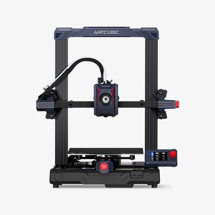
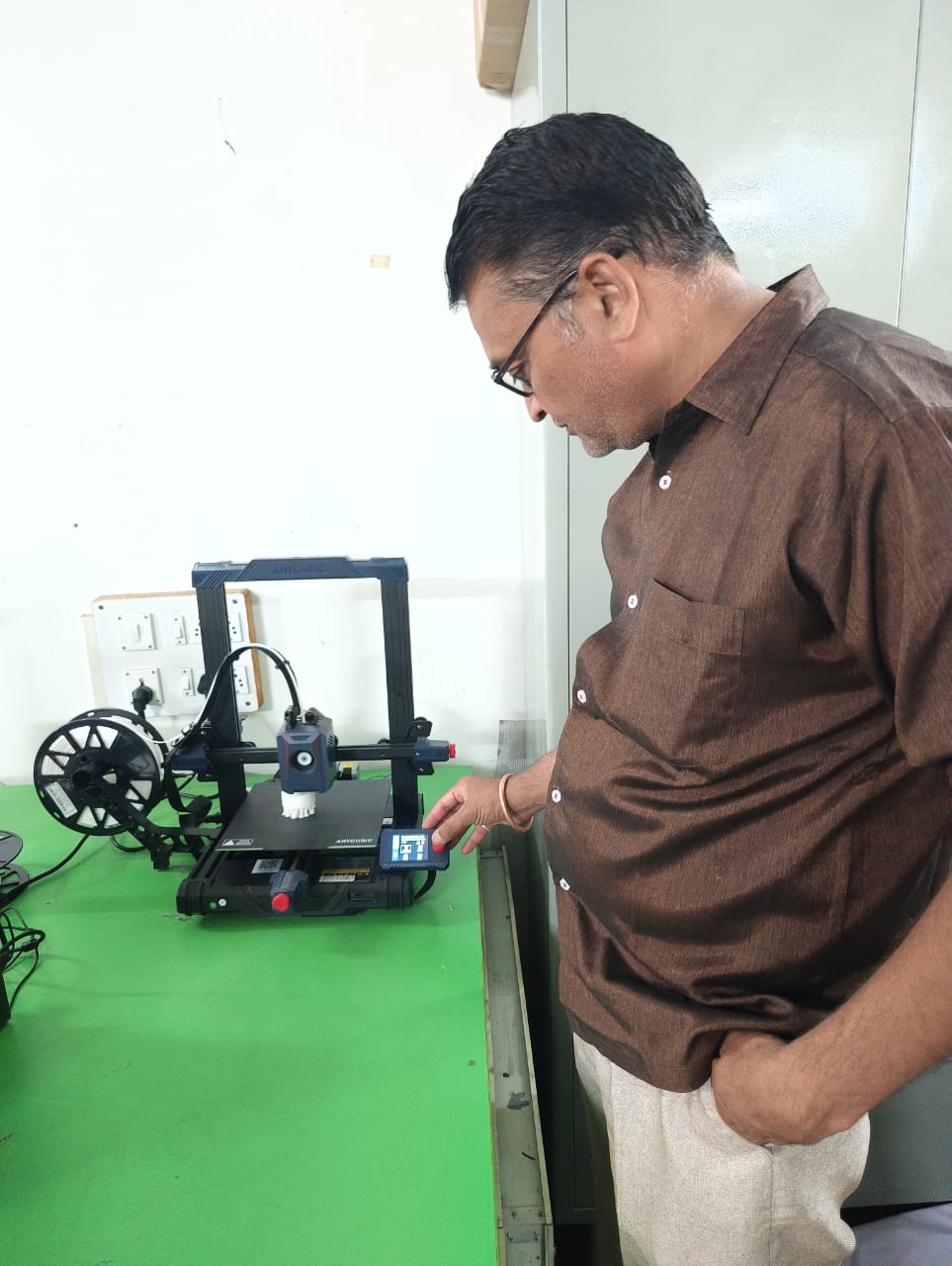
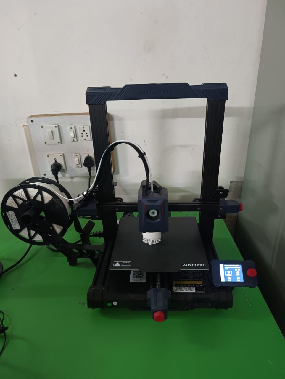
Printer Details
This machine is being used this week for both my group and individual assignments.
Build volume: 9.8x8.7x8.7in./ 250x220x220mm(HWD)
Printing volume: 3.2gal./12.1L
Printing speed: 250mm/s(Max.)/150mm/s(Typ.)
Machine leveling: New Anycubic LeviQ 2.0 Automatic Leveling System (25-point)
Cooling fan rpm: 7000rpm/min
Build platform: Spring Steel Magnetic Platform 8.7x8.7in./220x220mm
Operating screen: 2.4" LCD Knob-Control
Slicing software: AnycubicSlicer
Material: PLA/ABS/PETG/TPU
Connection method: MicroSD Card
Machine dimensions: 19.1x17.3x17.3in./485*440*440mm(HWD)
Machine weight: 7.3kg
Printer Characterisation
We decided to print the majority of the design rule components using STL files provided in the academy class. Additionally, we printed one part from 3DBenchy. Used PLA material for printing all components. Finally, we compared our printed parts with the reference dimensions provided.
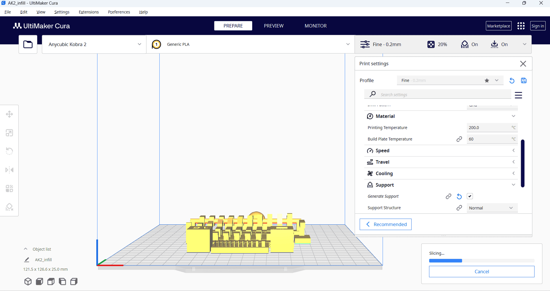
First, we downloaded the STL files for all parts to generate their G-codes. We then imported all STL file into the Ultimate cura slicing software to generate the G-code required for the 3D printer.
Then, right-click and select "Arrange All Models" to automatically arrange all models in a specific layout. Next, navigate to the print settings and select the "Fine 0.2mm" profile. Set the layer height to 0.2 mm, and configure additional parameters such as infill density, infill pattern, print temperature, build plate temperature, print speed, support structure and material settings as required.
After selecting all the parameters, press "Slice" and save the file to a memory card.
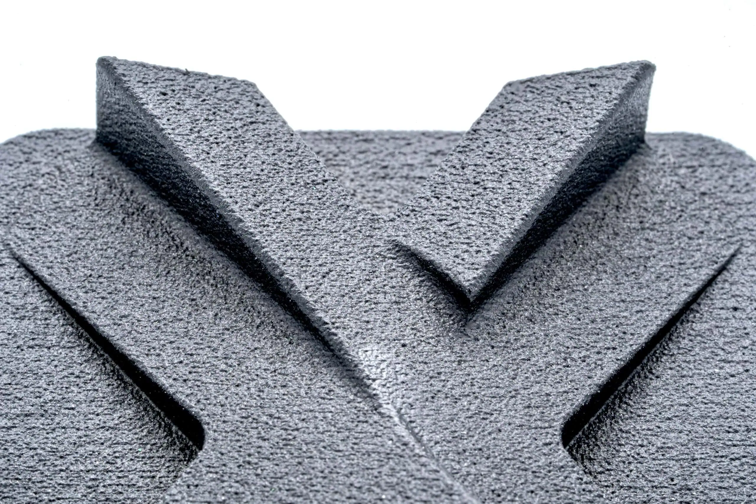
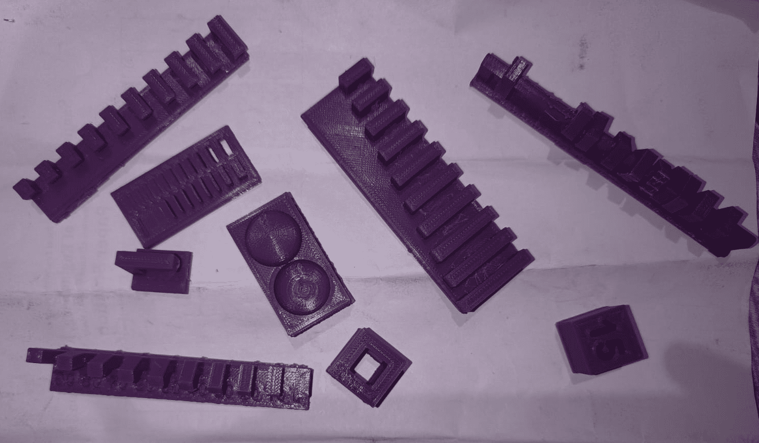
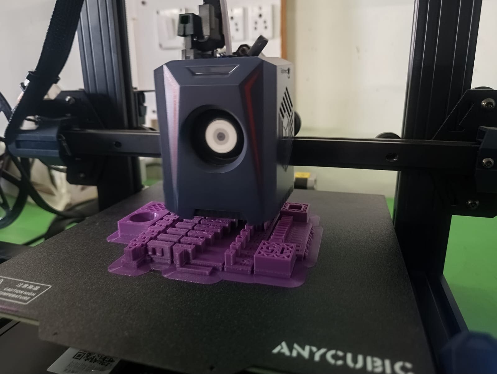
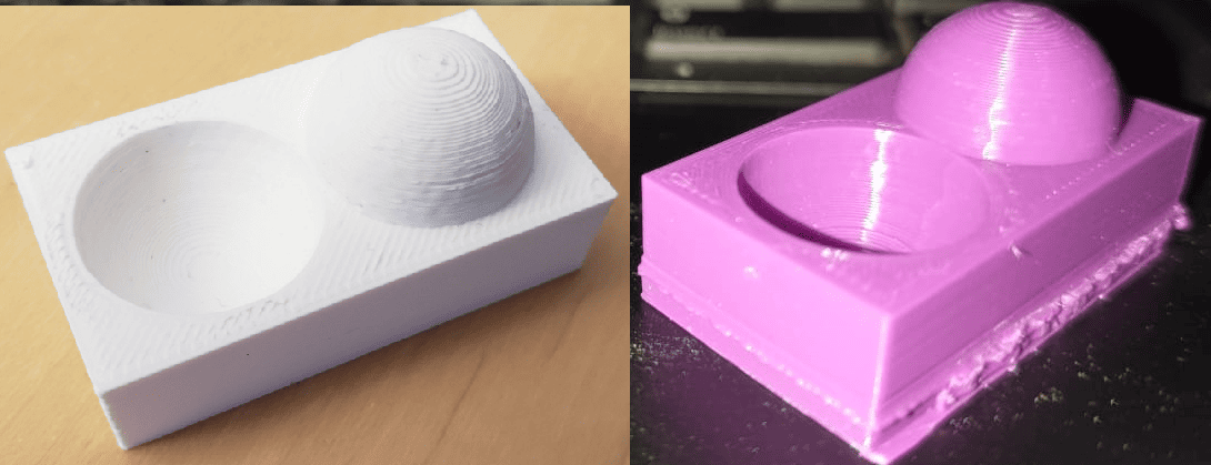
After setting up our 3D printer with Nozzle temperature as 210 deg C and bed temperature as 60 deg C. Following are some pictures and video of our final job we printed to test the design rules for our in-house 3D printer.
Componant printed to test Design rule for our 3d printer.
Conclusion
1. Clearance With Support
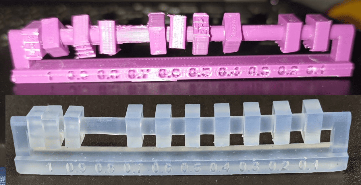
In this part, the 0.1 mm and 0.2 mm sections are fixed with support, while the sections from 0.3 mm to 1 mm move freely.
2. Angle without Support
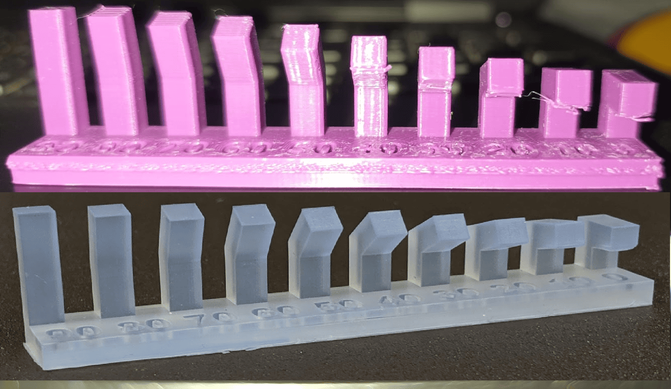
In this part, angles above 50° are printed successfully, while angles up to 40° require support.
3. Overhang without Support
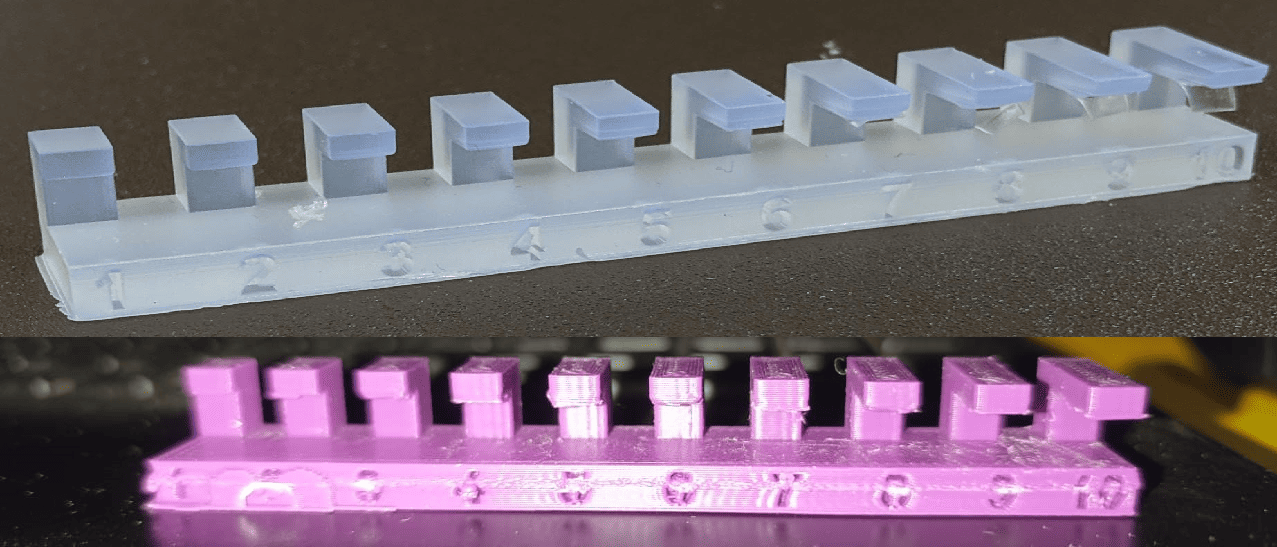
The part is successfully printed with an overhang of 4 mm and below, but any overhang above this requires support.
4. Bridging with Support
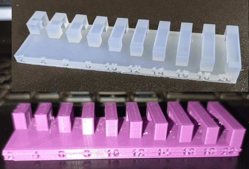
The part is successfully printed with a bridging distance of 20 mm without support.
5. Wall thickness without Support
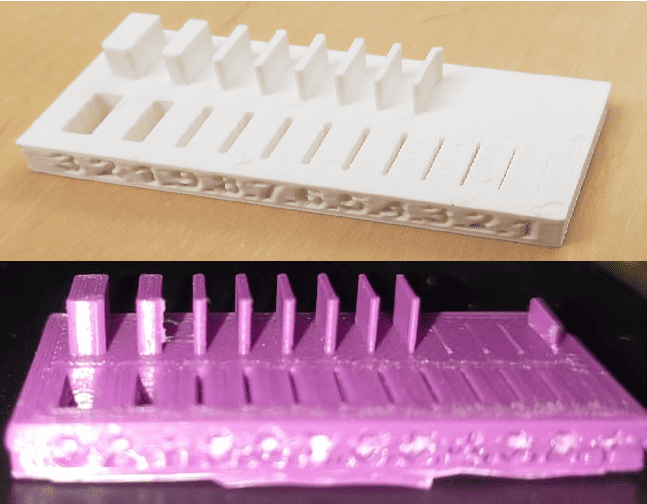
The walls are successfully printed at 0.5 mm and above, while walls thinner than this tend to break.
6. Diamensions
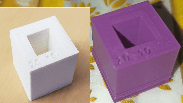
The outer dimensions of the cube are 20 × 20 mm, while the inner dimensions are 10 × 10 mm.
7. Surface Finish
surface finish of the part is good.
The group assignment is linked here
Indivisual Assignment
3D printing is an advanced manufacturing technology that enables the creation of complex geometries that are difficult or impossible to achieve using traditional subtractive manufacturing methods. This assignment focuses on designing and 3D printing a small object within the constraints of printer time.
Additionally, a 3D scanning process will be performed to capture the geometry of a real-world object. This will involve using a 3D scanner or a mobile-based scanning application to generate a digital 3D model, which can be further analyzed or reproduced using 3D printing. This hands-on experience with 3D scanning and printing will enhance understanding of digital fabrication techniques
Objectives
1. Operate a 3D printing machine effectively.
2. Understand the machine settings and follow all safety precautions.
3. Design and 3D print a small object, considering printer time limitations, that cannot be produced through subtractive manufacturing.
4. Perform a 3D scan of an object.
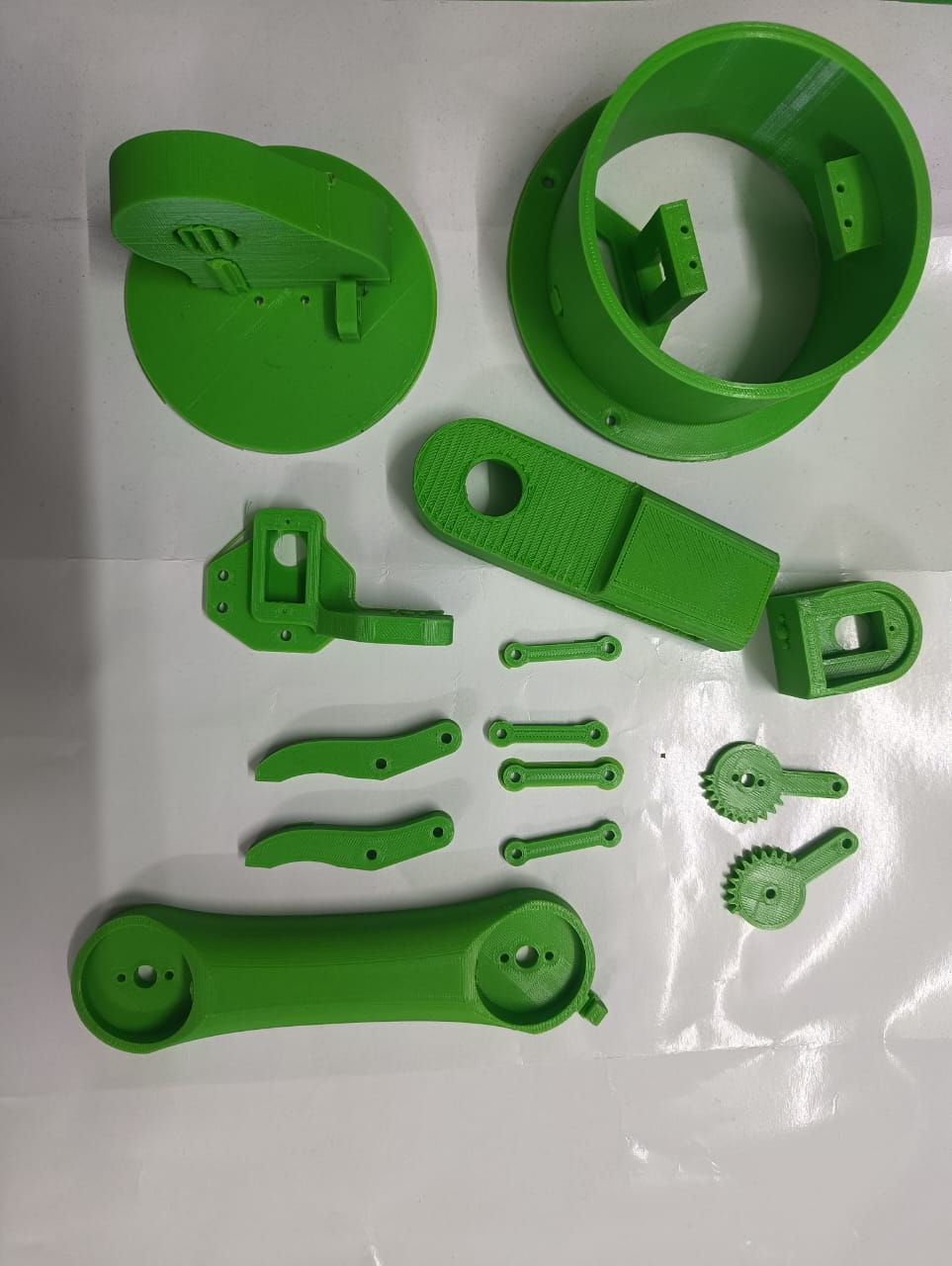
3d modeling of Robotic Arm
This week, I selected a robotic arm for my individual assignment. Since this robotic arm is a major component of my final project, its design and manufacturing using 3D printing were completed during this week.
I used SolidWorks 3D software to design the part. Using this software, I first designed the base component.
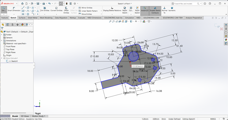
1. Base
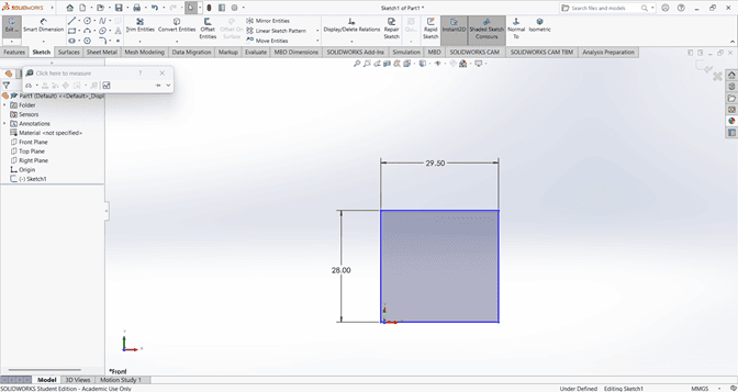
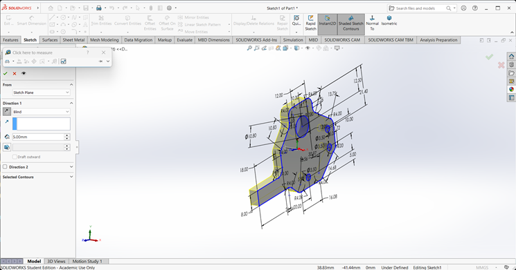
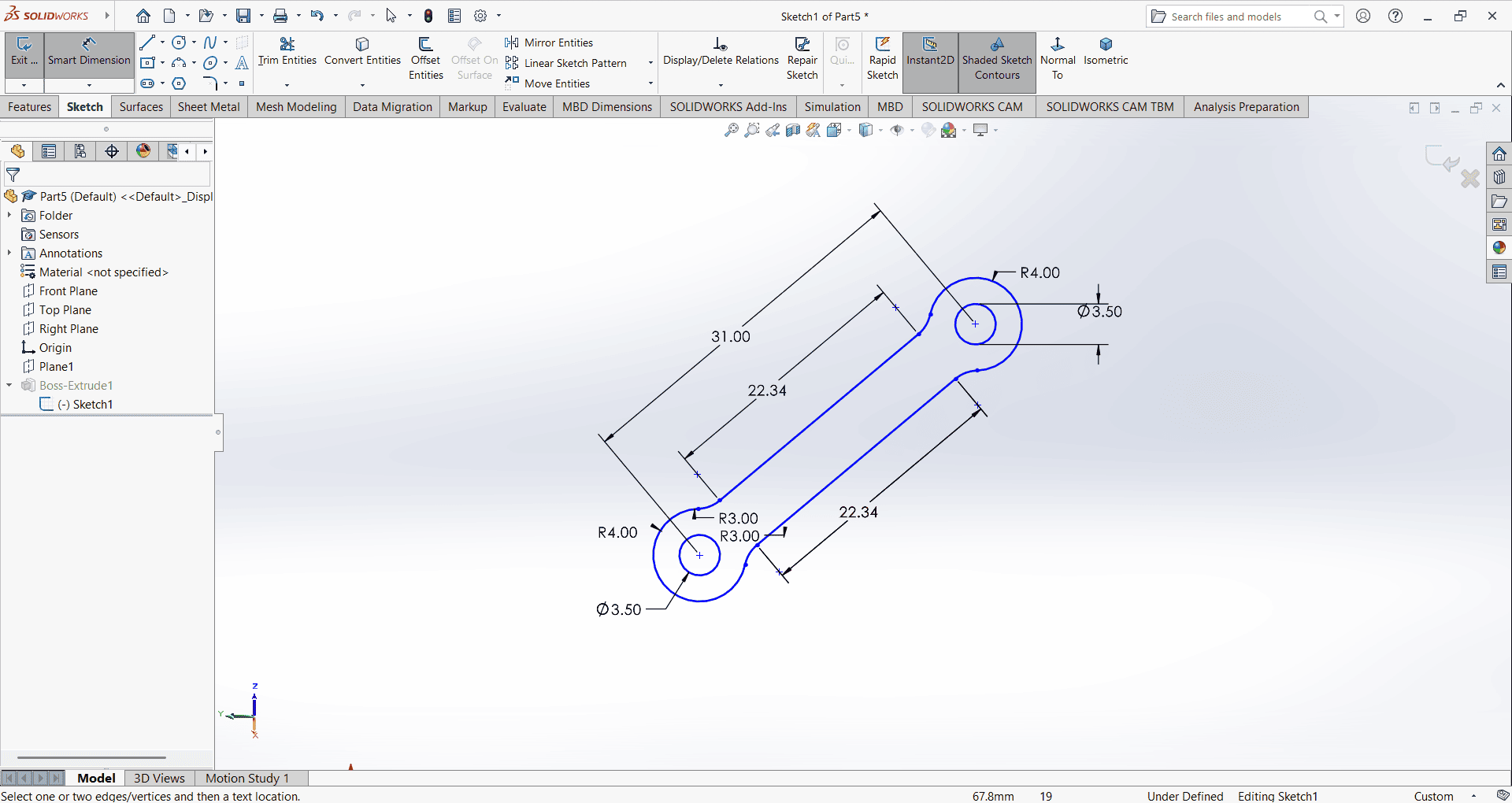
When starting the base design, I first created an accurate 2D sketch using various commands such as Circle, Trim, Line, and Rectangle.
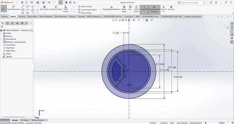
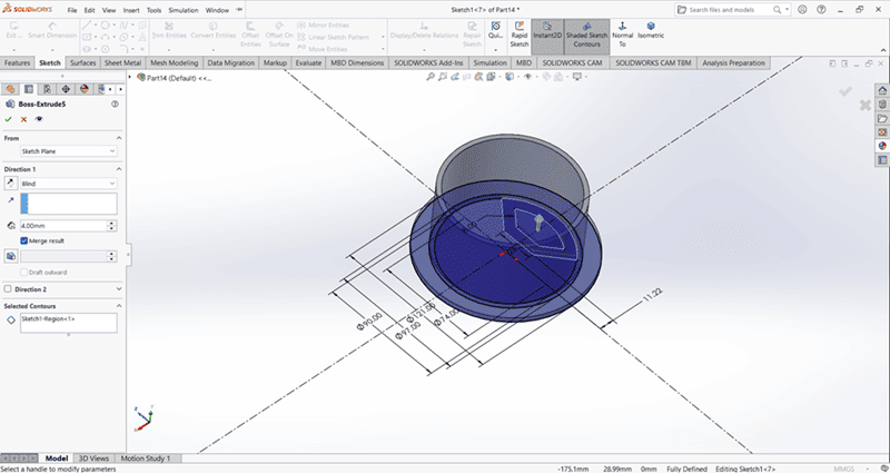
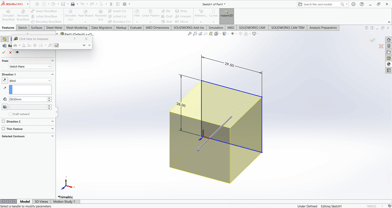
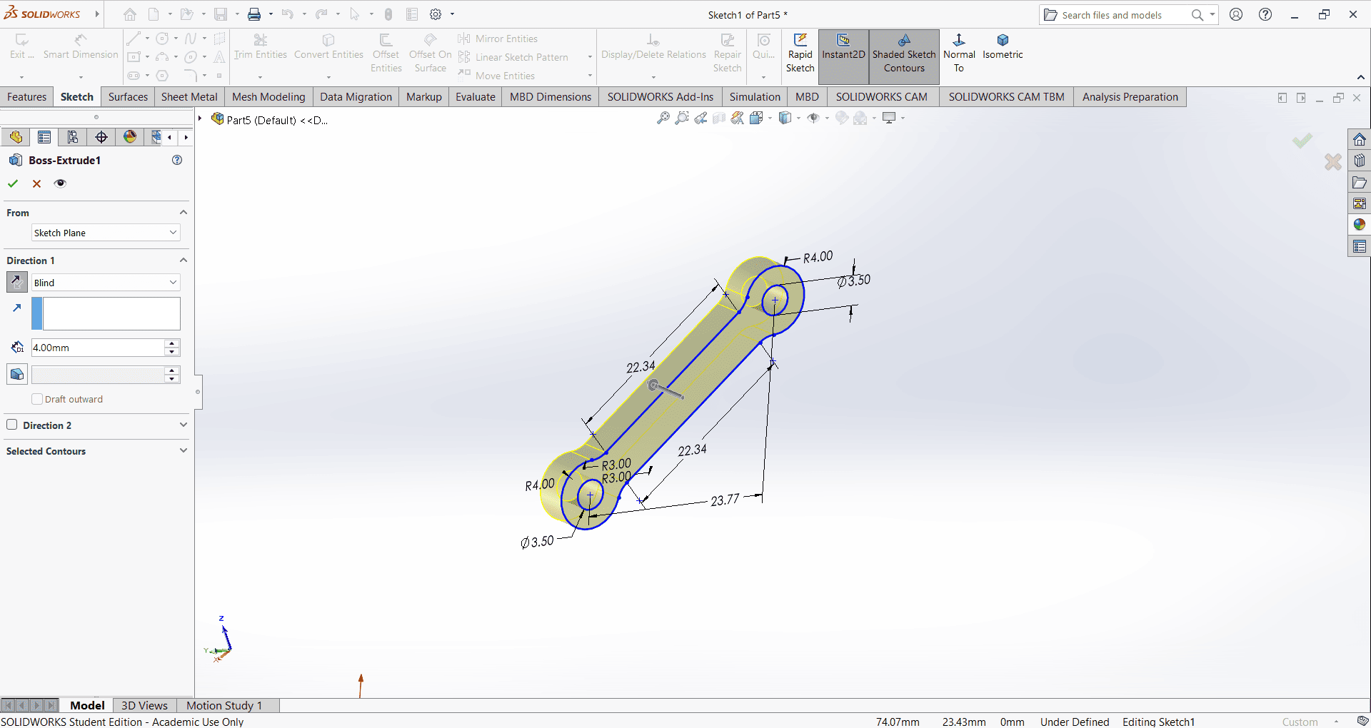
Then, I used the Extrude Boss/Base command to extend the part to the desired height
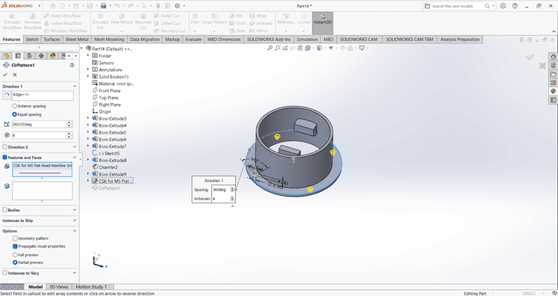
Using the Circular Pattern command, create four evenly spaced small holes along the periphery of the base.
Use the Cut Extrude command to create a circular hole in the base
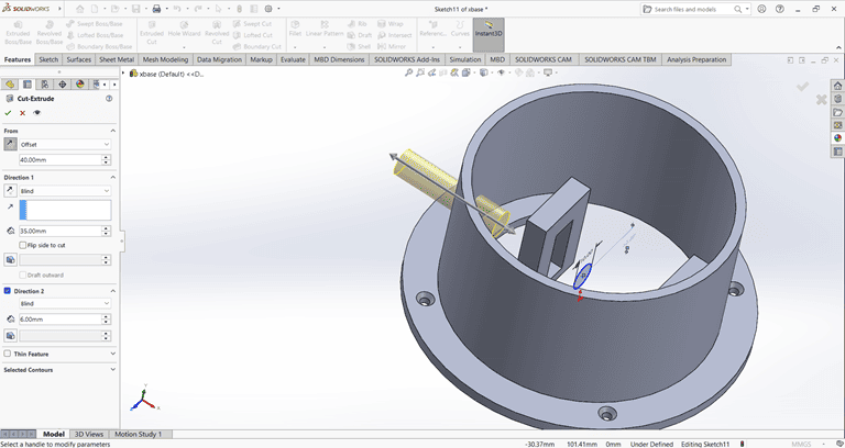
2. Arm 1
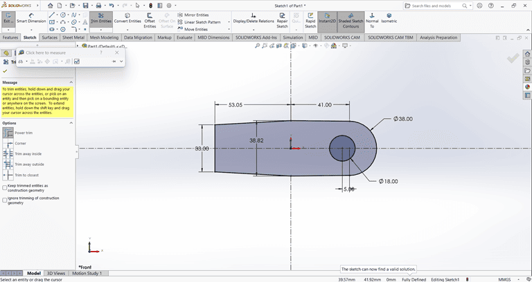
When starting the arm 1 design, I first created an accurate 2D sketch using various commands such as Circle, Trim, Line, and Rectangle.
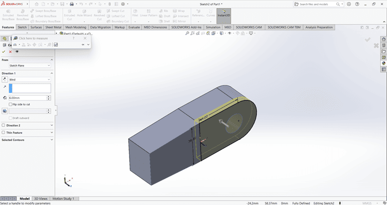
Then, I used the Extrude Boss/Base command to extend the part to the desired height
Next, I used the Cut Extrude command to create a circular hole in the arm at the desired depth.
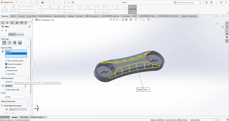
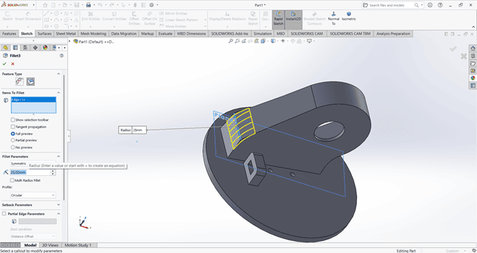
Then, use the Fillet command to round the edges of the rectangular shape, applying a fillet radius of 10 mm.
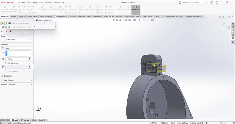
Next, create a small feature on the outer side of the arm and extrude it using the Midplane option. Then, use the Cut Extrude and Boss-Base commands to achieve the required shape.
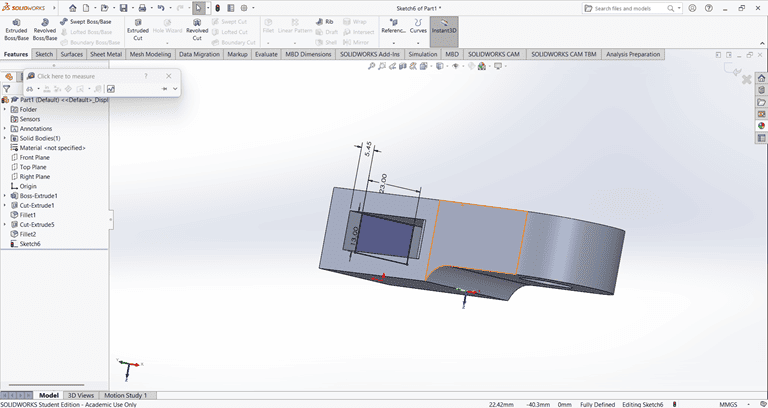
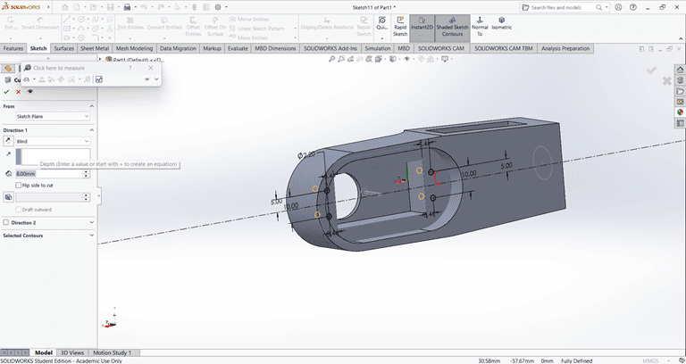
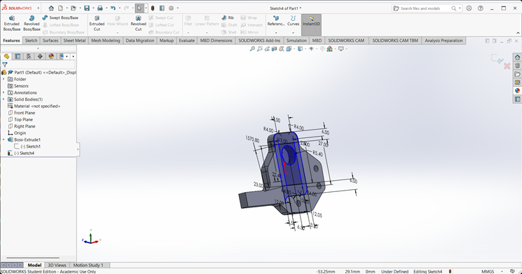
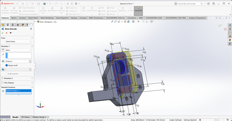
2. Arm 2
When starting the arm 2 design, I first created an accurate 2D sketch using various commands such as Circle, Trim, Line, and Rectangle.
Then, I used the Extrude Boss/Base command to extend the part to the desired height
Next, I created a rectangle of the required dimensions on the side face. Then, I used the Cut Extrude command to create a rectangular hole through the shape.
Next, I created a circle of the required dimensions on the side face. Then, I used the Cut Extrude command to create a circular hole with the specified dimensions in the shape.
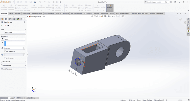
Next, I created the desired shape as shown in the figure. Then, I used the Cut Extrude command to shape it according to the specified dimensions.
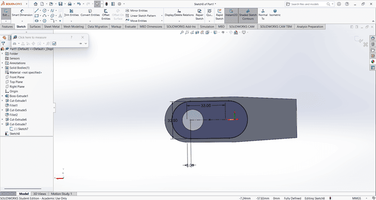
Next, a rectangular shape was created on the same face where the previous Cut Extrude command was applied. Then, the Cut Extrude command was used again to cut through the entire shape.
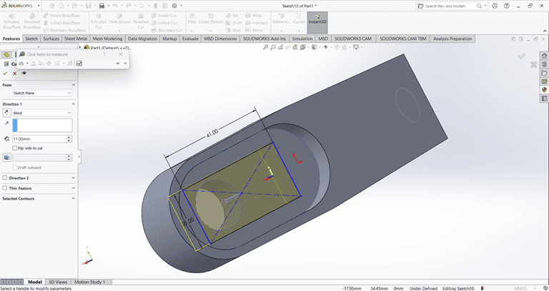
Finally, the arm part is complete and ready for use.
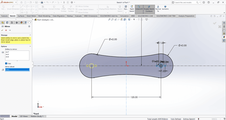
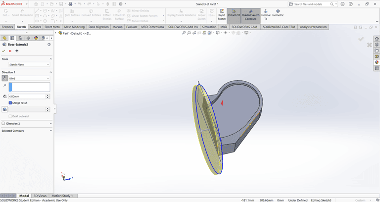
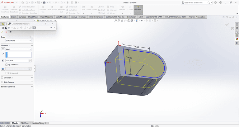
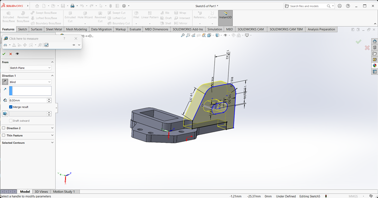
3. Base
I first created an accurate 2D sketch using various commands such as Circle, Trim, Line, and Rectangle.
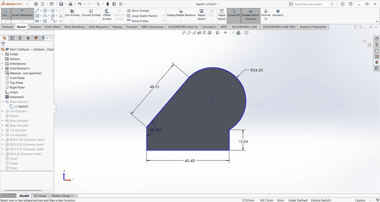
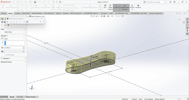
Then, I used the Extrude Boss/Base command to extend the part to the desired width.
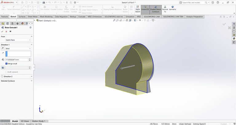
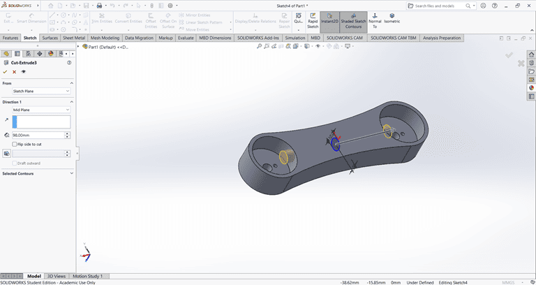
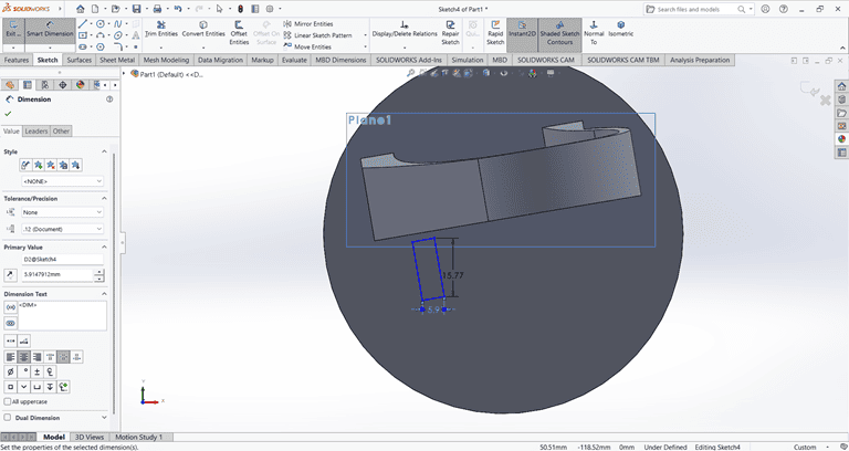
Next, I sketched the required shape on the front face to perform the cut operation.
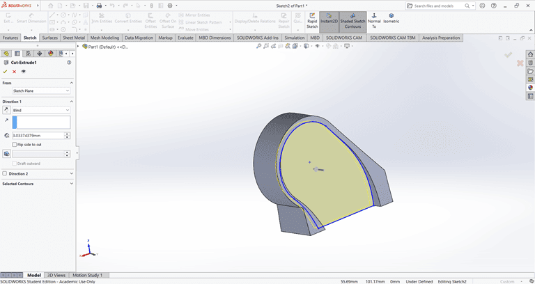
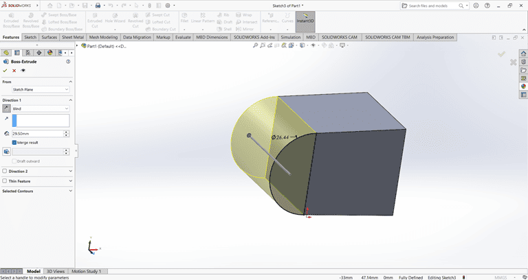
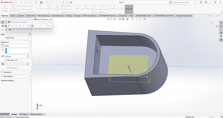
Next, on the bottom face, I first located the center point and then used the Circle command to draw a circle. After that, I applied the Extrude Boss/Base command to create the base.
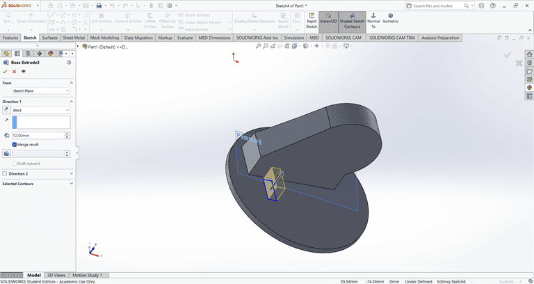
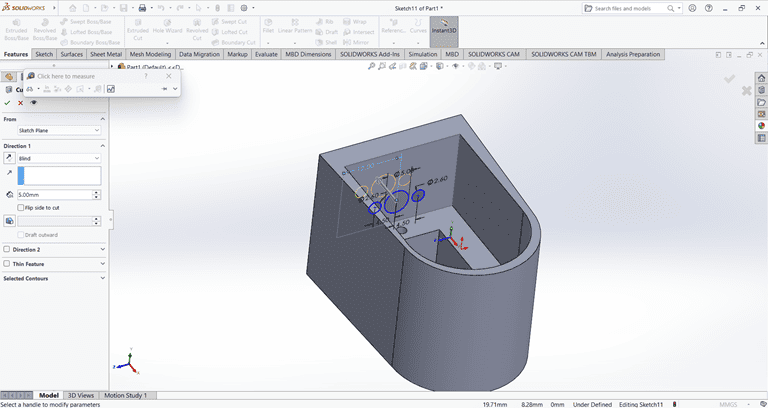
Next, I selected the top face and drew a rectangle at the specified location. Then, I applied the Extrude Boss/Base command. After that, I selected the side face of the rectangle and used the Cut Extrude command to create a rectangular hole.
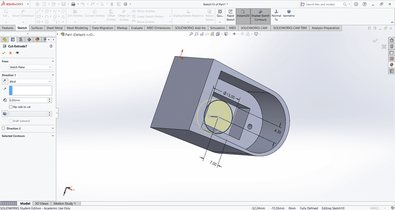
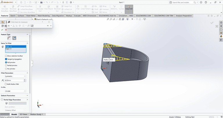
Next, I applied the Fillet command to the small rectangle with a fillet radius of 3 mm.
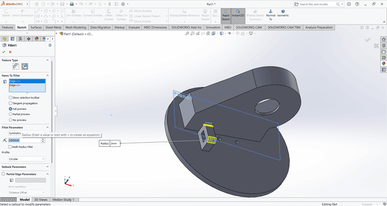
Next, I applied the Fillet command to the main shape with a fillet radius of 20 mm.
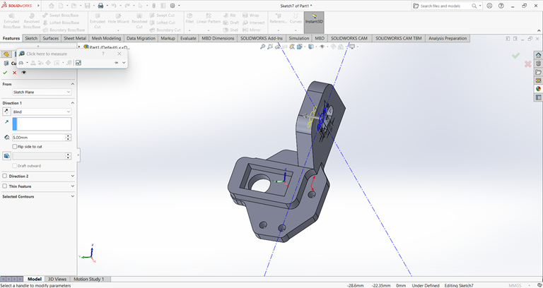
4. Joint
I first created an accurate 2D sketch using various commands such as Circle, Trim, Line, and Rectangle.
Then, I used the Extrude Boss/Base command to extend the part to the desired width.
Next, I created a half-circle on the top of the rectangle.
I created a precise 2D sketch using various commands such as Circle, Trim, Line, and Rectangle.
Next, I used the Cut Extrude command to remove that part. Then, on the same face, I sketched a rectangle to be cut in the next step.
Next, on the same face, I used the Circle command to draw a circle with the specified dimensions.
Next, on the bottom side, I used the Circle command to draw a circle with the specified dimensions. Then, I applied the Cut Extrude command to remove that shape.
Next, I drew a triangle on the side face using the Line and Dimension commands. Then, I applied the Cut Extrude command to create a slanted edge.
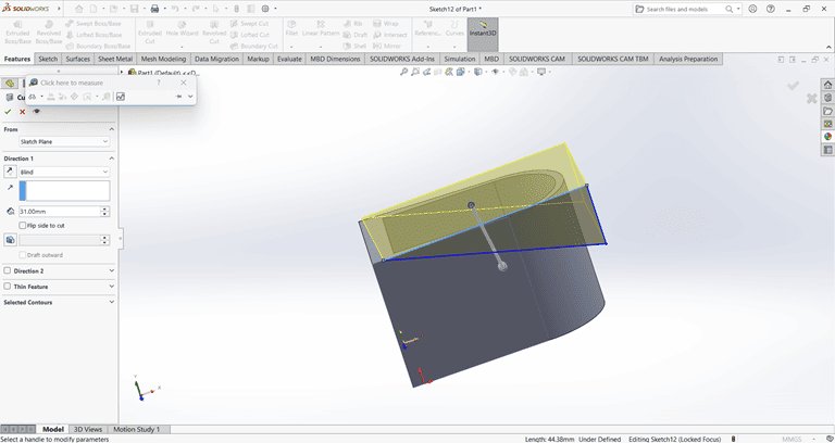
then on that slant edge apply the fillet command of 4mm to edge make circular.
5. Clip
I first created an accurate 2D sketch using various commands such as Circle, Trim, Line, Dimension and Rectangle.
Then, I used the Extrude Boss/Base command to extend the part to the desired width.
Next, on the front face of the extruded part, I created a 2D sketch of the desired shape for extrusion.
I extruded that part upward to the desired height.
On the side face, I created a 2D sketch and extruded it to a width of 8 mm.
Finally, the clip part is complete and ready.
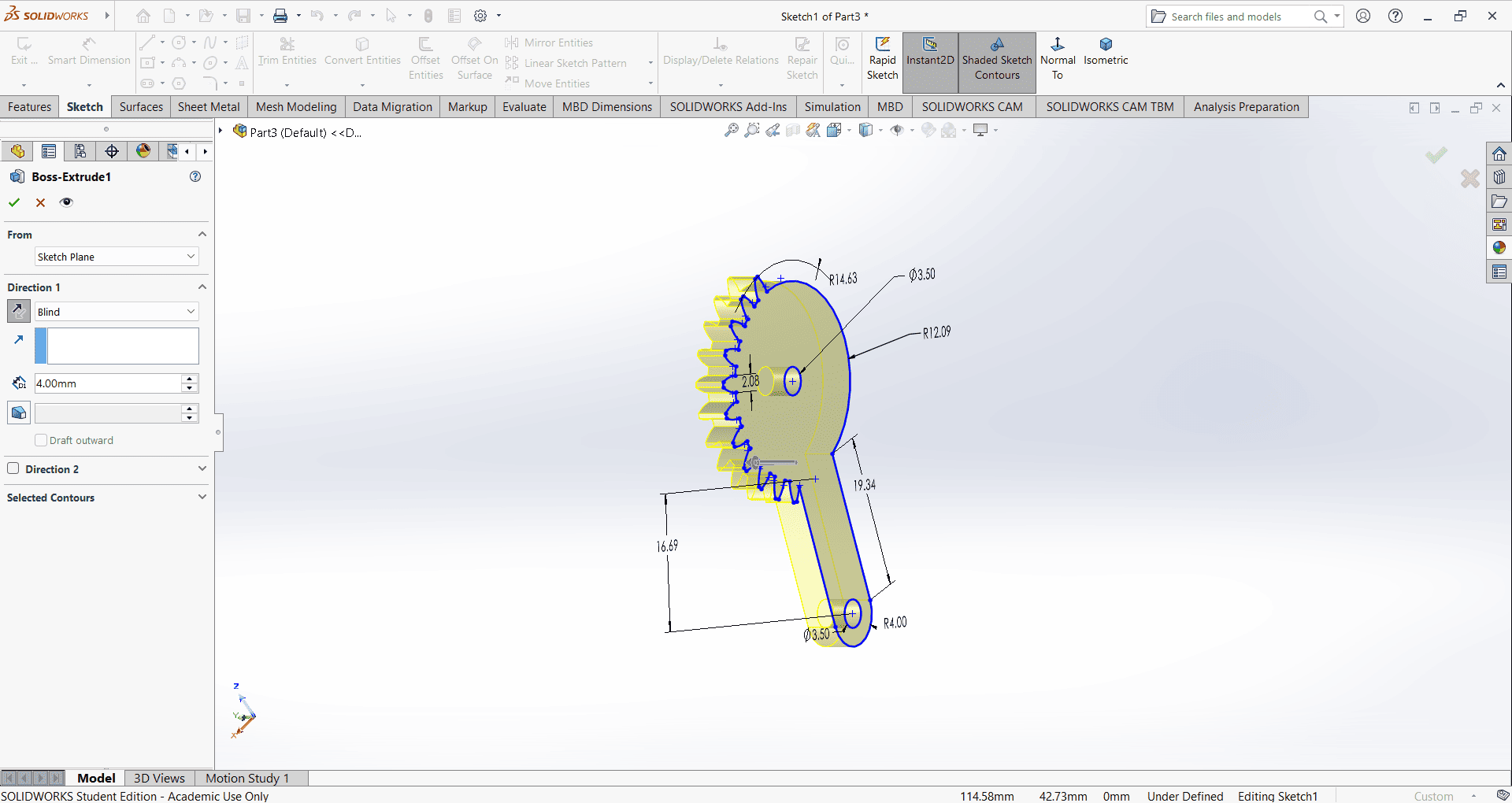
6. Gear
I first created an accurate 2D sketch using various commands such as Circle, Trim, Line, Dimension and Rectangle.
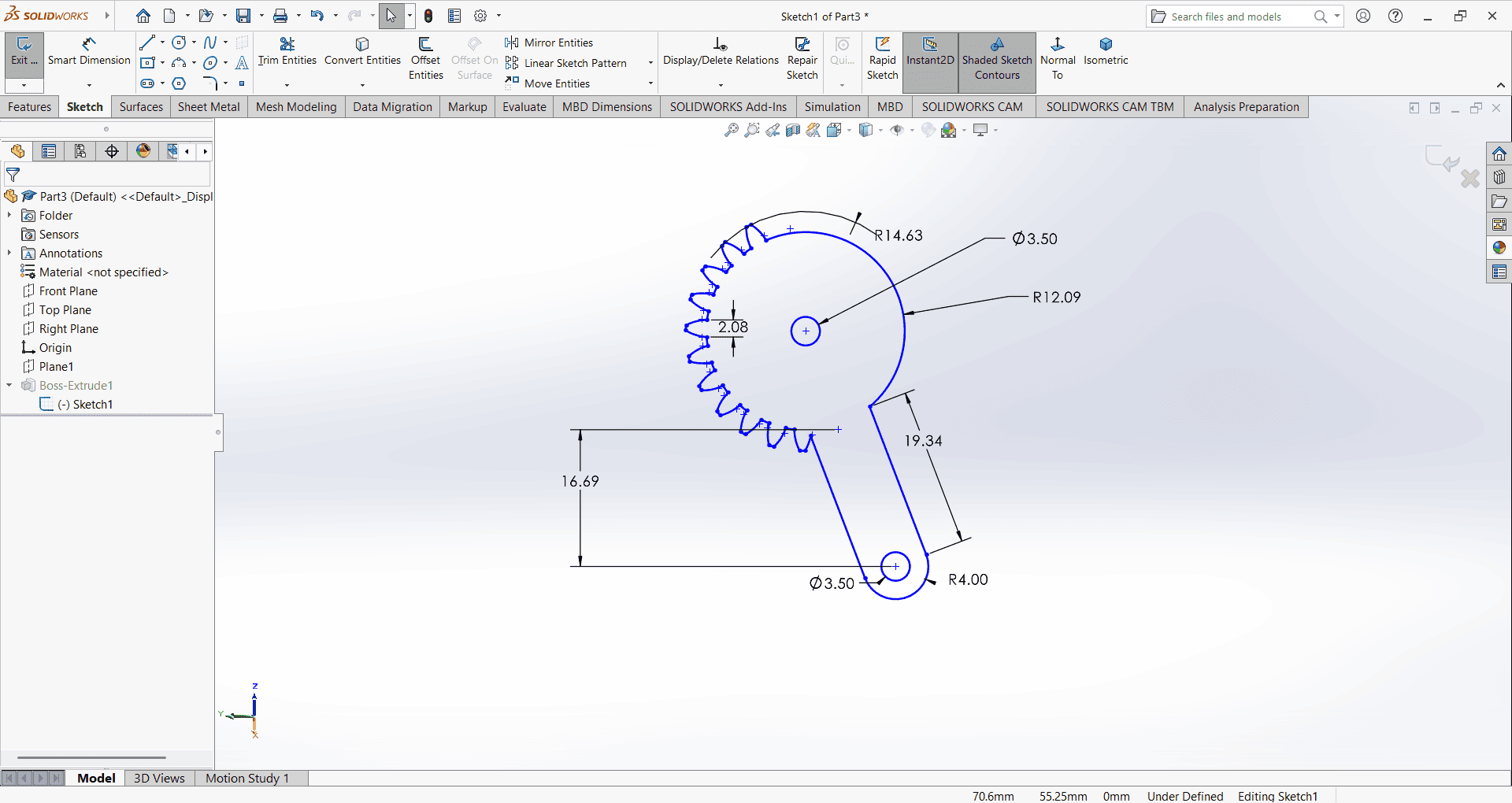
Then, I used the Extrude Boss/Base command to extend the part to the desired height.
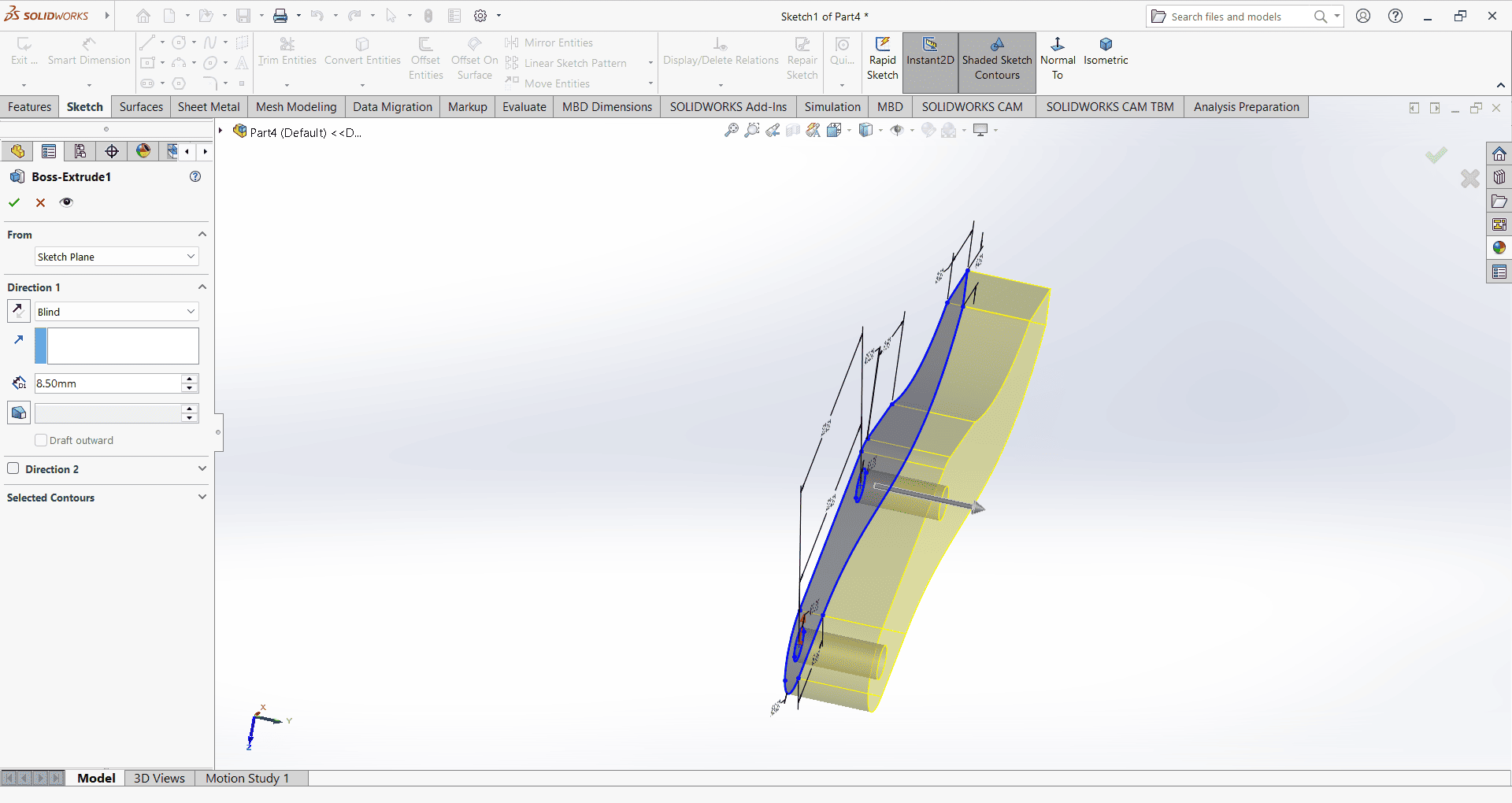
7. Gripper
I first created an accurate 2D sketch using various commands such as Circle, Trim, Line, Dimension and Rectangle.
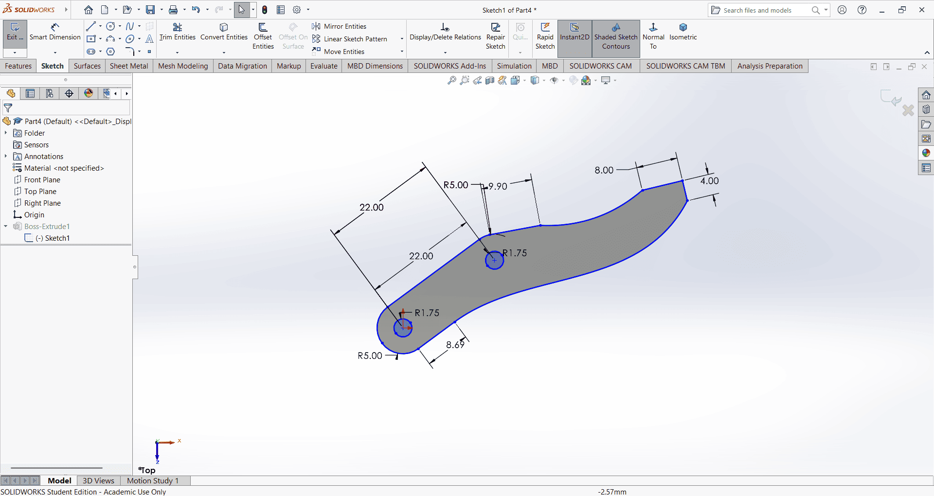
Then, I used the Extrude Boss/Base command to extend the part to the desired height.
8. Pin
I first created an accurate 2D sketch using various commands such as Circle, Trim, Line, Dimension and Rectangle.
Then, I used the Extrude Boss/Base command to extend the part to the desired height.
Slicing
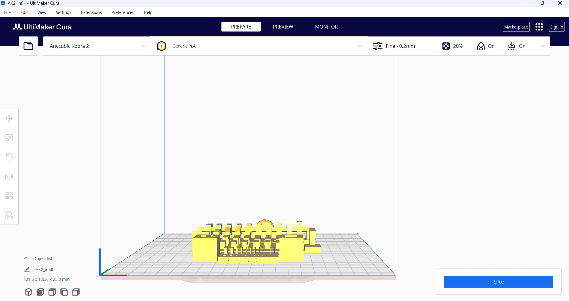
First, I downloaded the STL files in solid works for all parts to generate their G-codes. We then imported all STL file into the Ultimate cura slicing software to generate the G-code required for the 3D printer.
I opened the Ultimaker Cura software and navigated to the File menu. Then, I selected the Import option and chose the previously saved files in STL format.
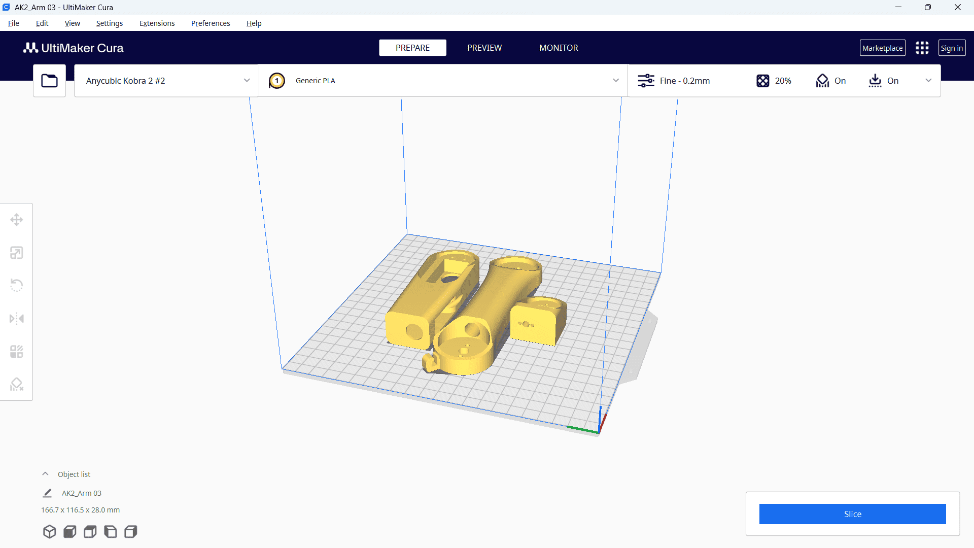
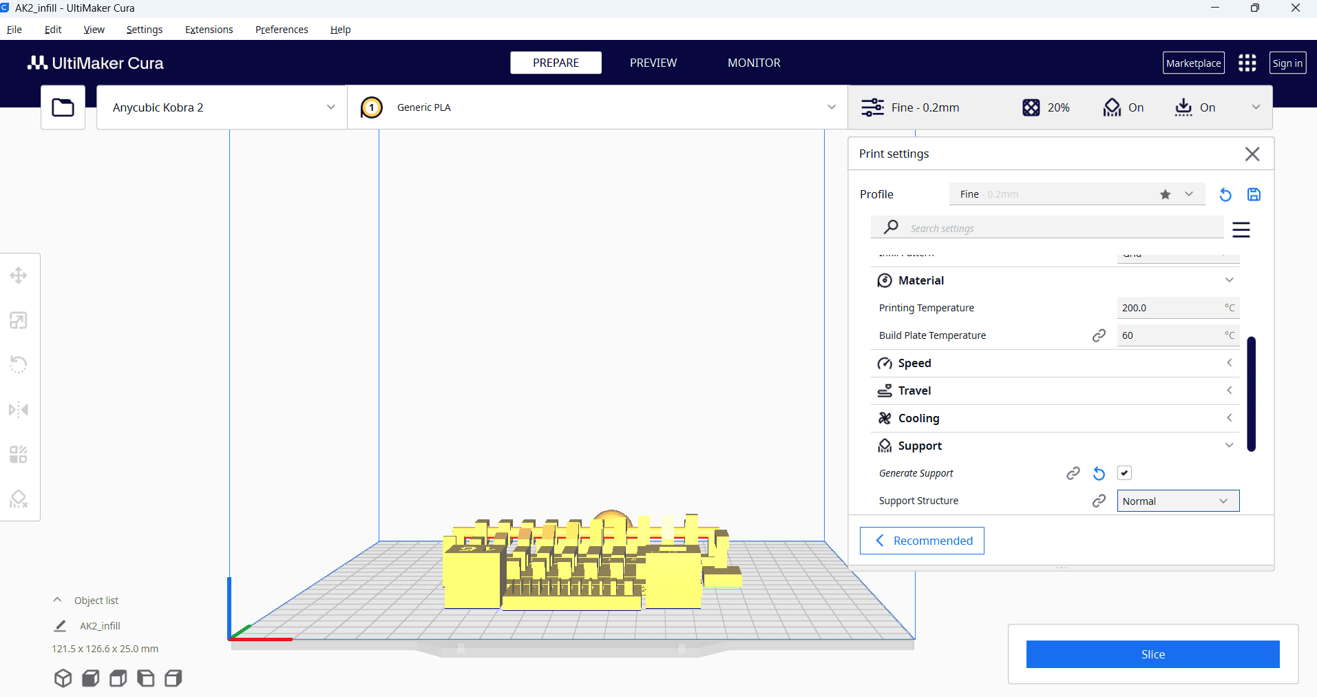
Then, right-click and select "Arrange All Models" to automatically arrange all models in a specific layout. Next, navigate to the print settings and select the "Fine 0.2mm" profile. Set the layer height to 0.2 mm, and configure additional parameters such as infill density, infill pattern, print temperature, build plate temperature, print speed, support structure and material settings as required.
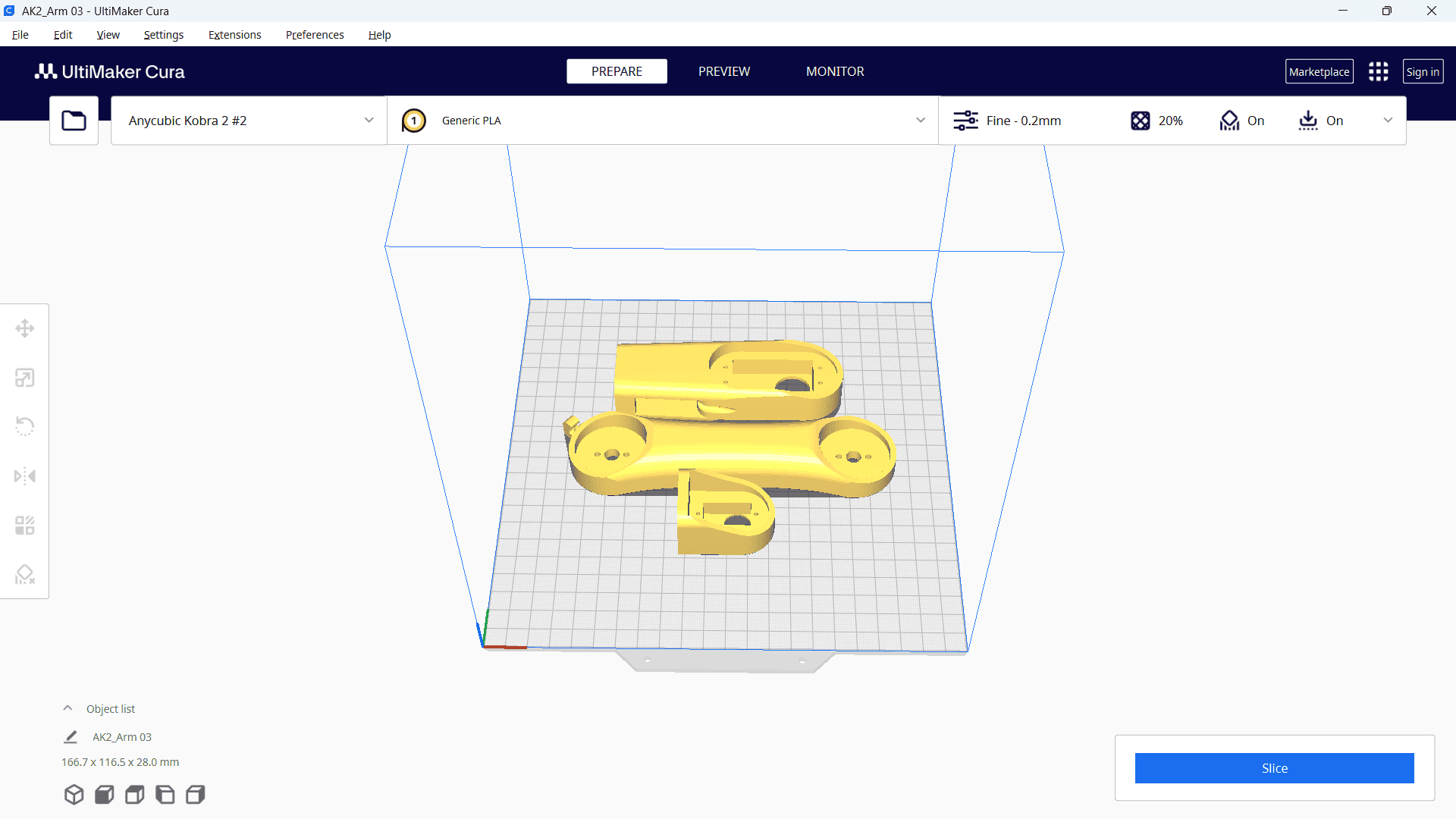
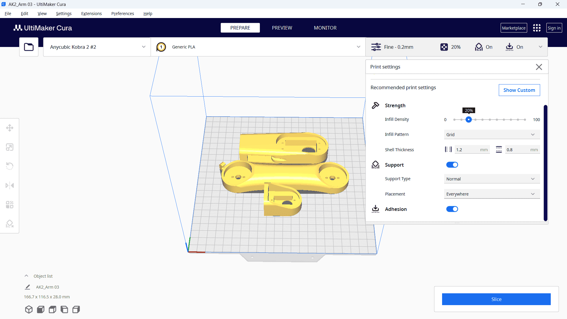
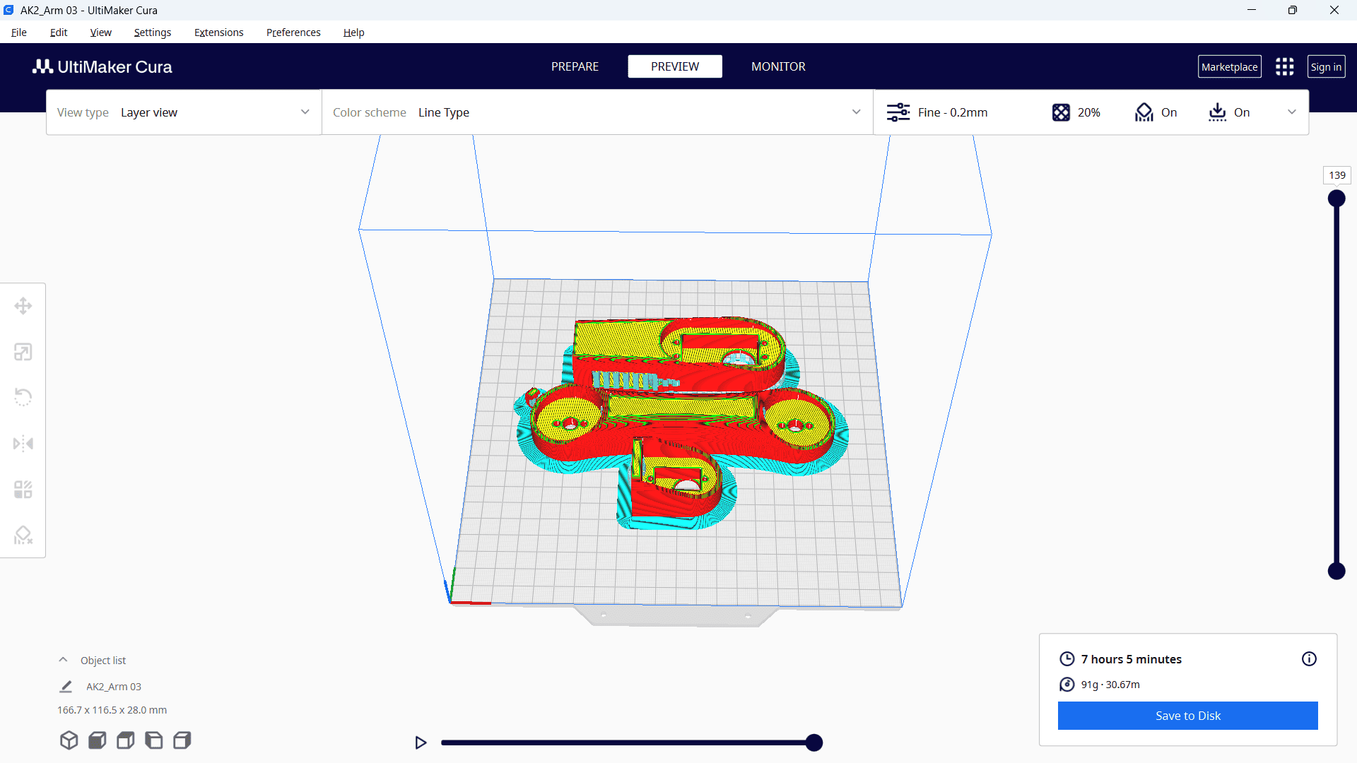
After selecting all the parameters, click "Slice." Once the processing is complete, the required printing time will be displayed.
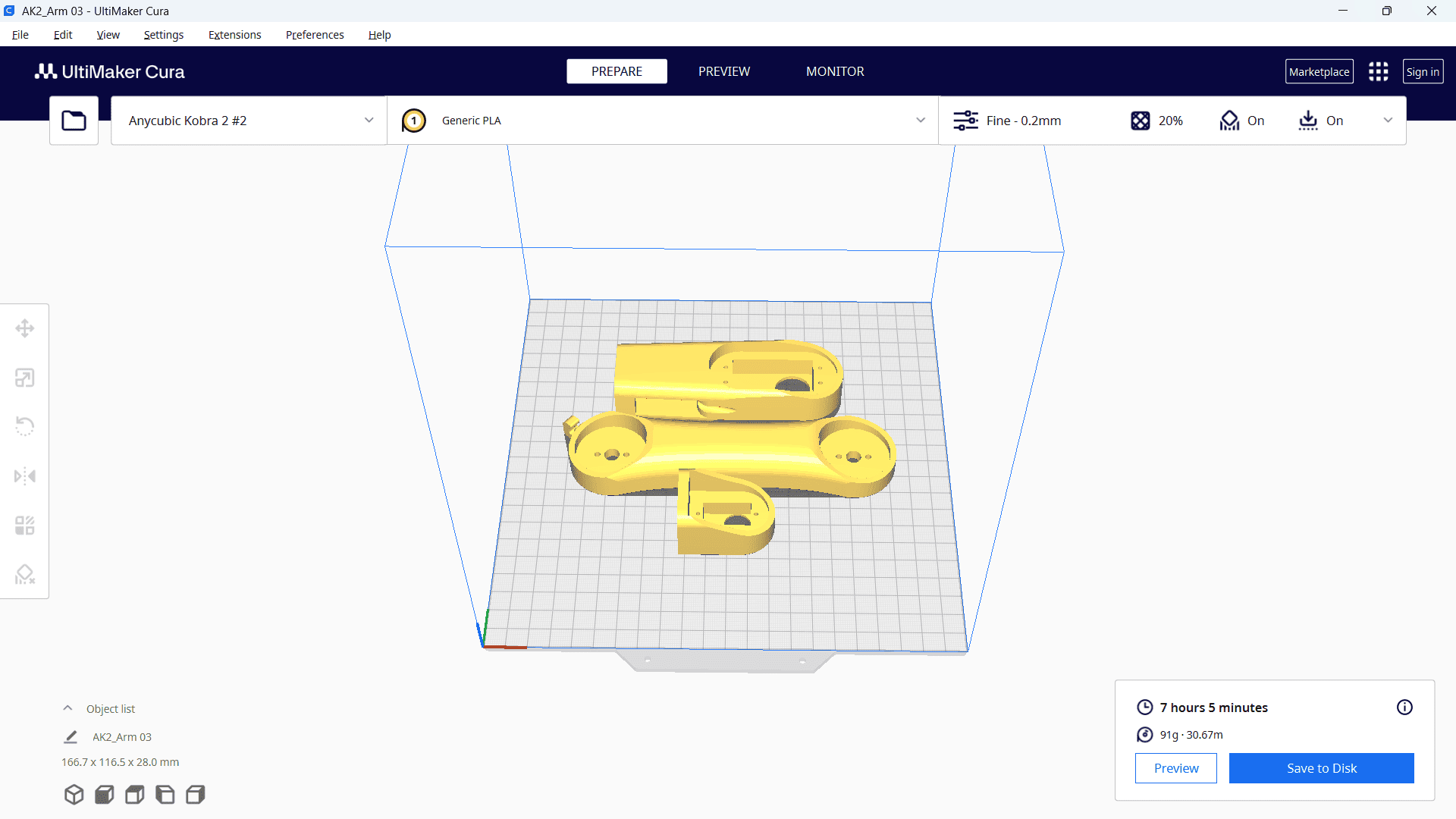
Finally, save the file to a memory card.
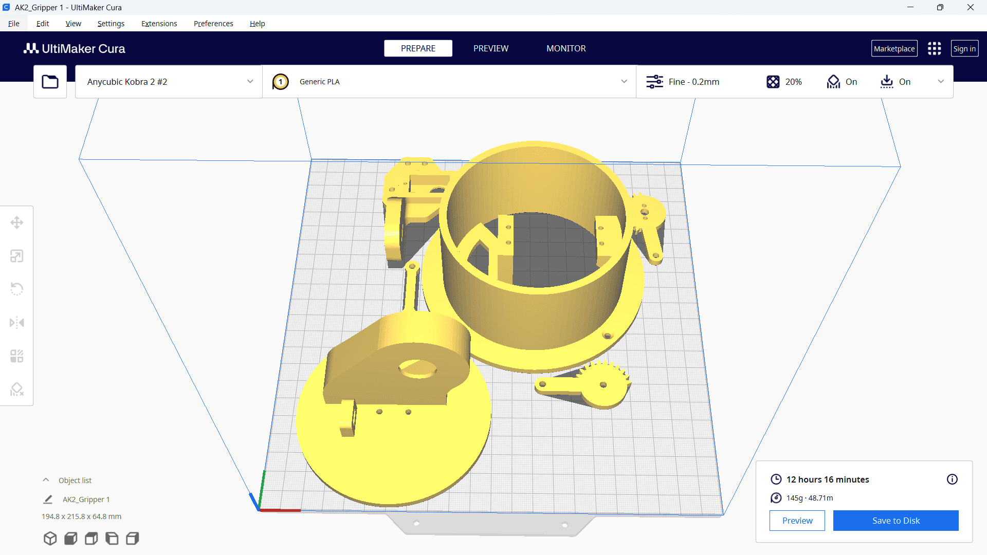
The same process was repeated for the remaining parts, which required 12 hours and 16 minutes for printing.
Printing
After setting up our 3D printer with Nozzle temperature as 210 deg C and bed temperature as 60 deg C.
Next, I selected the file from the memory card inserted into the machine and started the printing process.
Finally, our part was successfully printed and ready for use.
3D Scanning and Photogrammetry
The method of 3D scanning involves using a scanner to record the form and appearance of an actual object or setting. Digital 3D models are then produced using the gathered data.
How it works
1. A 3D scanner can capture an object's height, width, depth, and, in some cases, its color.
2. It can acquire millions of data points from real-world objects.
3. Additionally, 3D scanning is a non-contact and non-destructive process.
Application
1. 3D scanning is widely used across various industries, including engineering, construction, and architecture.
2. It is utilized for documenting and assessing the condition of structures.
3. Additionally, it plays a crucial role in quality inspection, reverse engineering, and heritage preservation.
4. Furthermore, 3D scanning is essential for additive manufacturing, digital twins, and dimensional analysis.
Types of 3D scanning
Laser 3D Scanning: Utilizes a laser as a light source to measure the distance to a surface.
Photogrammetry: Captures multiple photographs and processes them to generate a 3D model.
Photogrammetry
As part of my assignment, select here Photogrammetry types of scanning. I scanned my own body to develop the 3D scanned model.
For this purpose, I used an iPhone 13 Pro. First, I downloaded the Polycam 3D Scanner LiDAR 360 on the device.
This application requires at least 20 images for 3D scanning. Therefore, the phone was rotated 360 degrees around me in a steady state, allowing it to capture more than 20 images from various positions.
Once the image capture is complete, the phone begins processing, and the 3D object is finally generated.