Week 12
Mechanical Design & Machine Design
As part of the group assignment, we designed and developed a Pick and Place Cartesian Robot that demonstrates the integration of mechanical design, actuation, automation, and application. The primary objective of this project was to build a machine capable of performing precise pick-and-place operations along the X, Y, and Z axes using a Cartesian coordinate system. Our design includes a linear motion mechanism with belts, pulleys, and guide rails, actuated by stepper motors and controlled through an embedded microcontroller system. Initially, the robot was assembled and tested manually to verify the mechanical functionality and movement accuracy. Later, we automated the motion using programming logic to allow the robot to pick objects from a specified location and place them at a desired position.
This project not only reflects our understanding of machine design but also showcases our ability to integrate mechanism, actuation, and automation into a working application. Each team member contributed to different aspects such as mechanical assembly, wiring and electronics, programming, and documentation. Through this collaborative effort, we were able to gain hands-on experience in building a functional robotic system that aligns with real-world industrial automation practices.
Objectives of the Project
1. Design and Develop a Cartesian Robot:
To design a functional pick and place robot using a Cartesian (XYZ) coordinate system capable of performing precise linear motion for object manipulation.
2. Integrate Mechanical and Electronic Systems:
To combine mechanical structures, actuation mechanisms (stepper motors, servo motors), and control electronics into a cohesive and reliable system.
3. Understand and Implement Motion Control:
To learn and apply the principles of manual and automated control of linear axes using embedded systems and appropriate programming.
4. Build a Functional Prototype:
To fabricate and assemble the physical structure using digital fabrication tools such as 3D printers and laser cutters, followed by hands-on testing.
5. Demonstrate a Practical Application:
To create a working prototype that can pick an object from a specific position and place it at a designated location, simulating real-world automation tasks.
6. Encourage Collaborative Development:
To work in a team setting, distributing responsibilities while contributing individually to various project phases including design, fabrication, coding, and documentation.
7. Document the Complete Process:
To thoroughly document the design process, challenges faced, solutions implemented, and lessons learned, for evaluation and future reference.
Group Assignment
As part of the group assignment, we collaboratively designed and developed an Advanced Cartesian Robot for high-precision bottle handling applications, specifically tailored for the production requirements
Individual Assignment
In my individual role, I contributed to the design and assembly of the robotic arm and vacuum gripper, focusing on the mechanical structure and end-effector integration. I also worked on wiring the control components and interfacing the stepper motor drivers with the Arduino Mega. Additionally, I participated in the calibration of the motion system and assisted in testing the full pick-and-place cycle. This task strengthened my practical understanding of embedded motion control, system integration, and automation within an industrial context.
DESIGN APPROACH
The design of the Advanced Cartesian Robot integrates both hardware and software elements to ensure precision, reliability, and scalability for high-precision bottle handling.
Hardware Architecture
The hardware architecture of the Cartesian Pick and Place Robot is designed to ensure high precision, modularity, and robust performance in automated material handling. It integrates mechanical, electrical, and electronic components into a cohesive system.
1. Base & Mounting Bracket
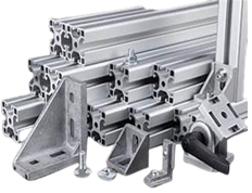
Aluminium rods are widely used in robot frame construction due to their lightweight nature, high strength-to-weight ratio, and excellent machinability. These properties allow for the creation of lightweight and robust frames, crucial for efficient robot movement and energy consumption. Additionally, aluminum’s corrosion resistance and good thermal conductivity make it suitable for various operating environments and assist in heat dissipation.
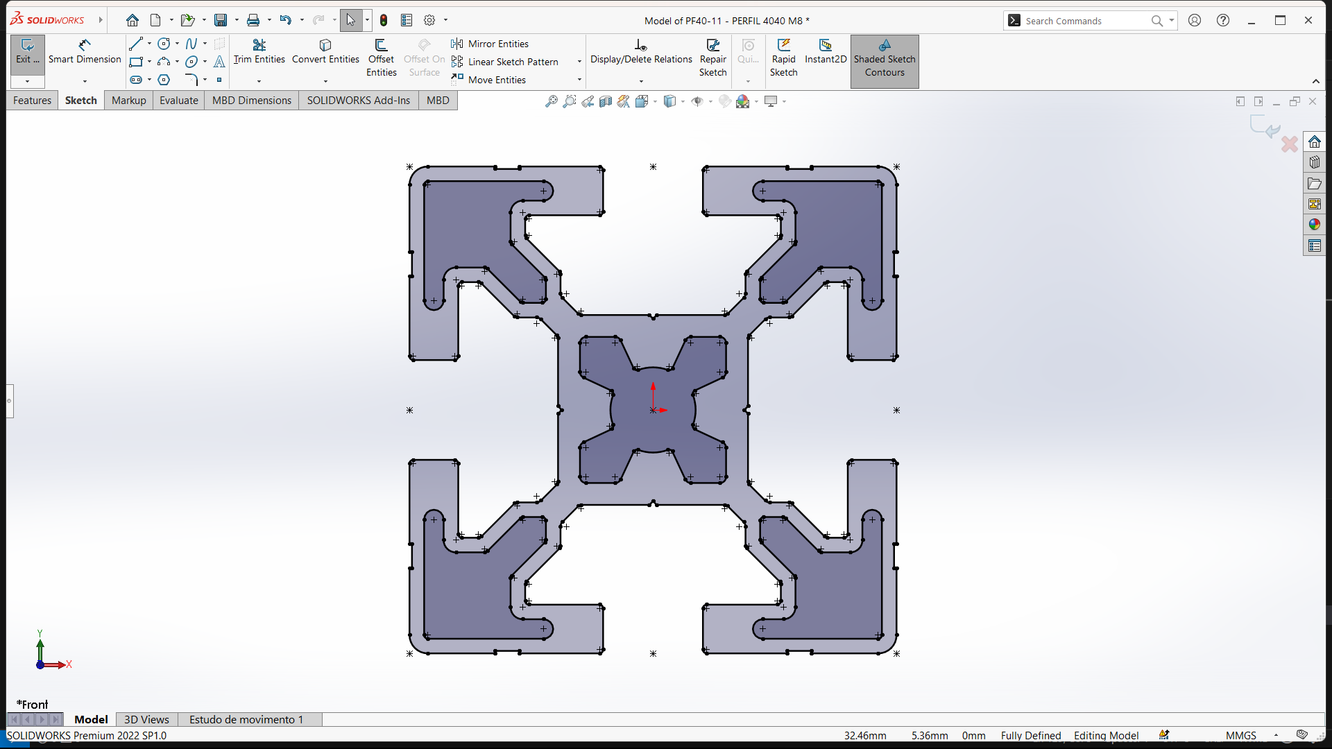
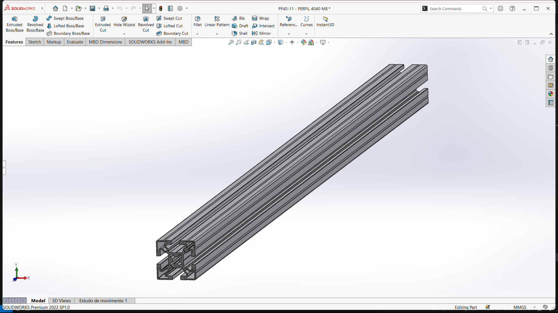
The image shows a 3D CAD model of a 4040 aluminum extrusion profile, created in SOLIDWORKS. This type of profile—often referred to as T-slot aluminum extrusion—is commonly used in machine frames, automation systems, CNC machines, and robotics due to its modularity, strength, and ease of assembly.
In the context of the Cartesian Pick and Place Robot, this 4040 profile likely serves as a structural frame component, providing a rigid and durable base for mounting linear guides, stepper motors, lead screws, and other mechanical elements. The T-slots on each face allow for adjustable and repeatable connections, making it ideal for prototyping and industrial-grade applications alike.
2. Conveyor belts
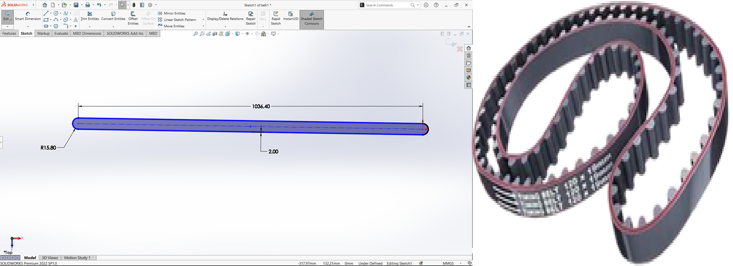
This image shows the 2D sketch of a conveyor belt in SolidWorks, which is likely part of a conveyor assembly
Sketch Overview:
Total Length: 1036.40 mm.
Width (Thickness): 2.00 mm.
End Radius: R15.80 mm on both sides, indicating rounded edges.
Shape: The profile is a slot (also known as a capsule or racetrack profile) — made from a long central rectangle with two semicircles on either end, which is a common shape for flat belt conveyors.
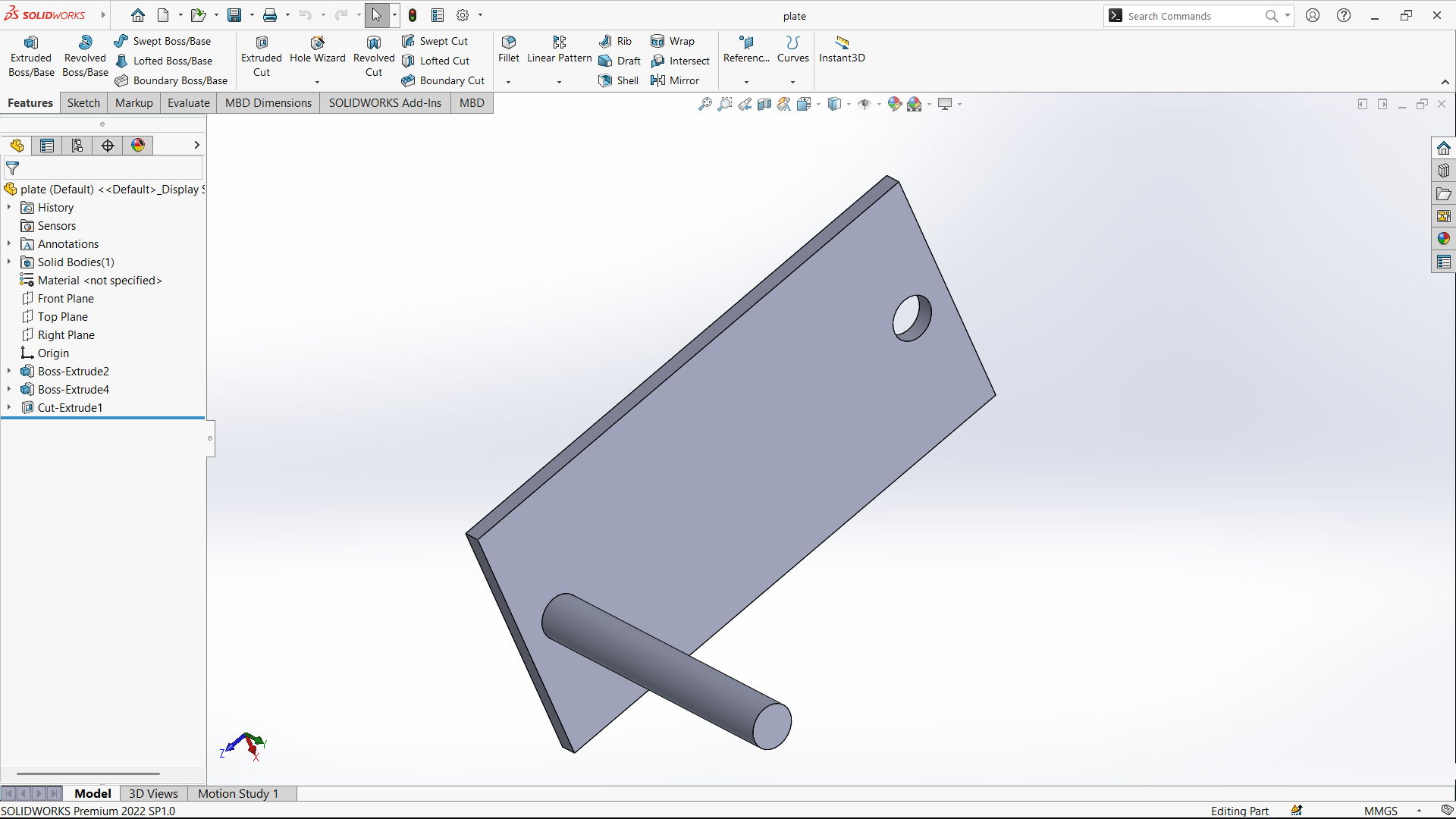
3. Plate with a cylindrical pin
This image shows a 3D CAD model of a plate with a cylindrical pin created in SolidWorks, likely as a part of a conveyor or robotic assembly.
Component Description:
1. Main Plate:
Rectangular base plate modeled using Boss-Extrude.
One circular hole made using Cut-Extrude, possibly for bolt fixing or shaft pass-through.
2. Cylindrical Pin:
Added with Boss-Extrude, extending perpendicularly from the plate.
Likely serves as a support pin, roller axis, or pivot joint.
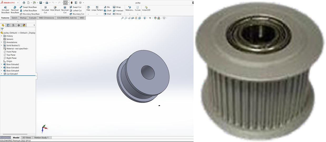
4. Pulley
This image displays a 3D CAD model of a pulley created in SolidWorks, which is likely a part of your conveyor belt or robotic system assembly.
1. Central Hub:
A cylindrical boss with a central cut-extruded hole, possibly for mounting onto a shaft or axle.
2. Pulley Rim:
Features a groove around the outer circumference—suitable for a belt drive system like a V-belt or flat belt.
The groove is likely made using a revolved cut or additional boss and cut features.
3. Purpose:
Used to transmit motion via the belt (e.g., conveyor belt drive).
May be mounted to a motor shaft or idler support.
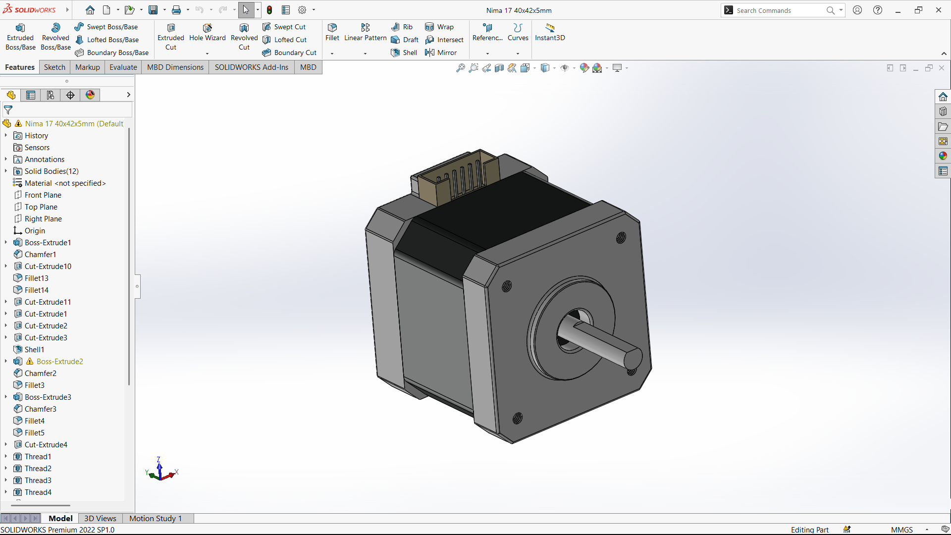
5. 3D model of a Stepper motor
Description of the Model:
Dimensions Mentioned: 40x42x5 mm, which suggests a variant of the standard NEMA 17 (typically 42mm x 42mm faceplate).
Features:
Front Plate with 4 mounting holes and a central shaft extruding out.
Rear Connector block representing a pin header for electrical connections.
Chamfers and Fillets applied on edges for realism and ease of manufacturing.
Threaded Holes on the front, likely for M3 or M4 screws.
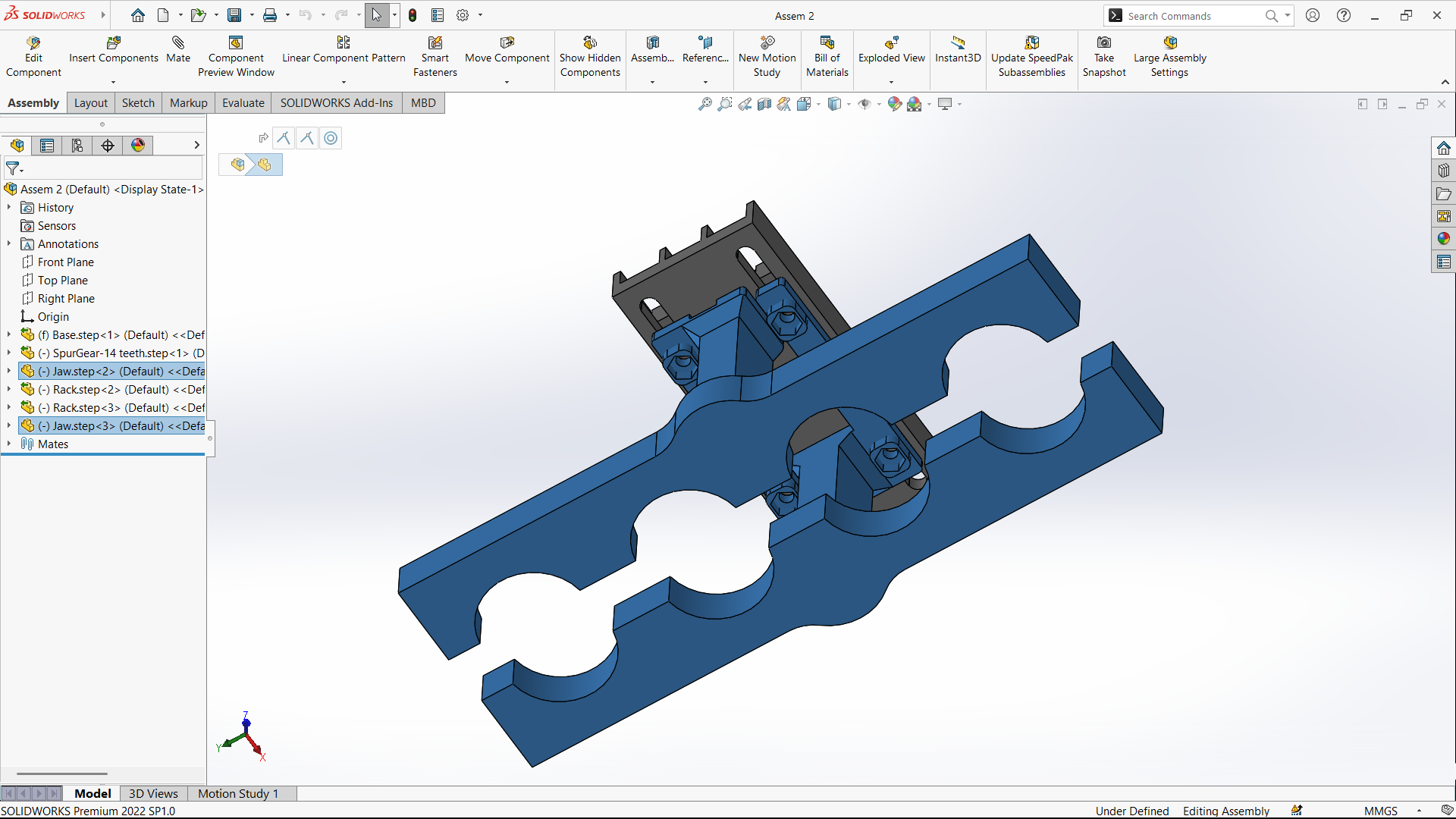
6. Gripper Assembly in SOLIDWORKS
The final gripper assembly was modeled in SOLIDWORKS, integrating multiple mechanical components to achieve a functional gripping mechanism. The design includes a base, jaw components, and rack-and-pinion gear mechanisms. The jaws are symmetrically placed and guided by racks connected to a central pinion gear (spur gear with 14 teeth), which ensures synchronized movement during the opening and closing action. Proper mates and constraints were applied to align all parts accurately and simulate their motion. This assembly demonstrates a practical approach to designing a mechanical gripper system.
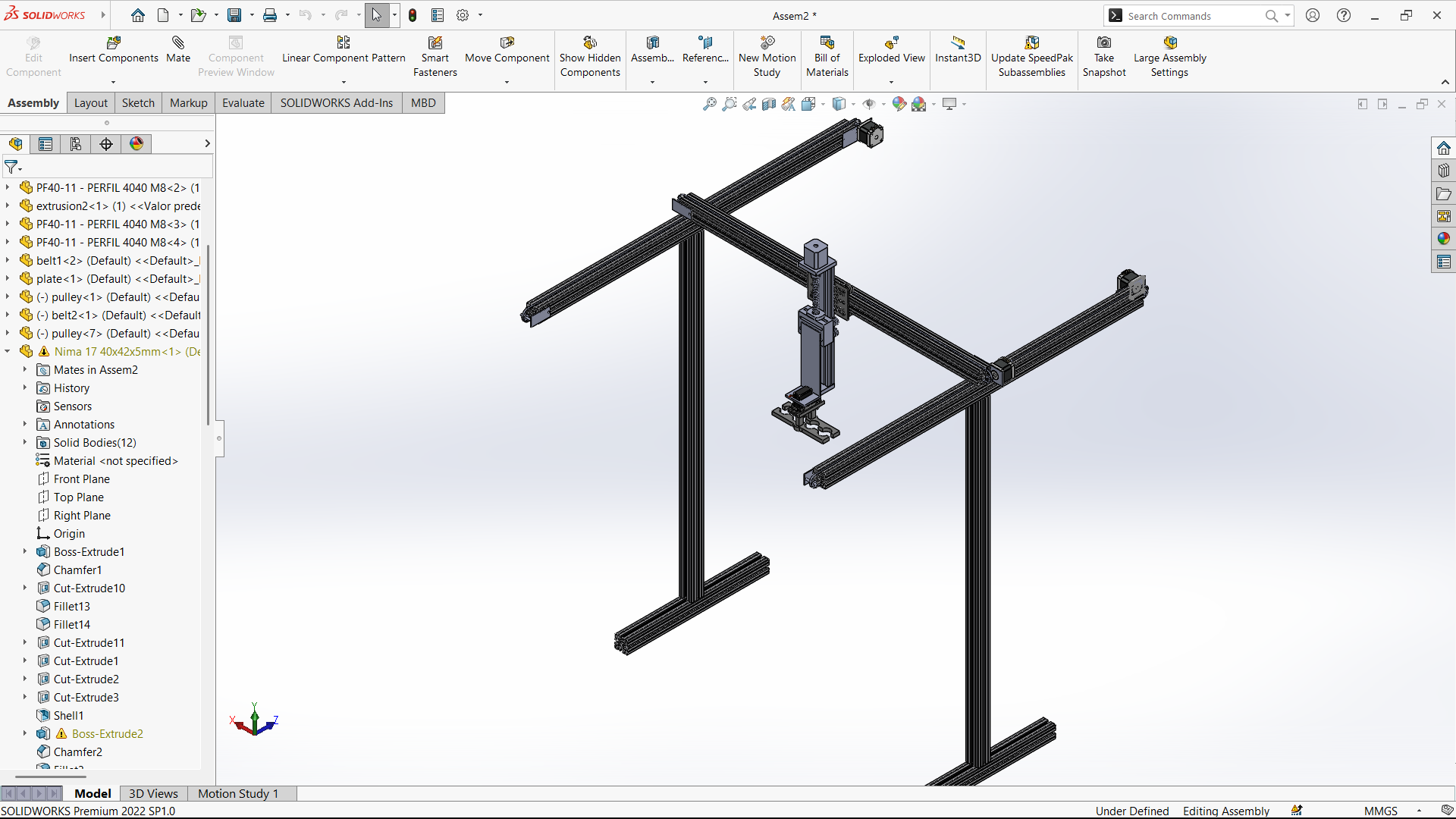
7. Final Assembly in SOLIDWORKS
Lastly, I completed the final assembly of my project using SOLIDWORKS. All the individual components, including the NEMA 17 stepper motor, structural elements, and other mechanical parts, were accurately modeled and assembled using proper mates and constraints. This allowed me to verify the mechanical fit, alignment, and movement of each component within the design. The final assembly not only helped in visualizing the complete system but also ensured that all parts function together as intended before proceeding to the manufacturing or prototyping stage.
ELECTRICAL CONNECTIONS
In the next step, I will start the electrical connections.
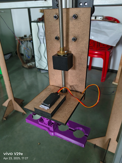
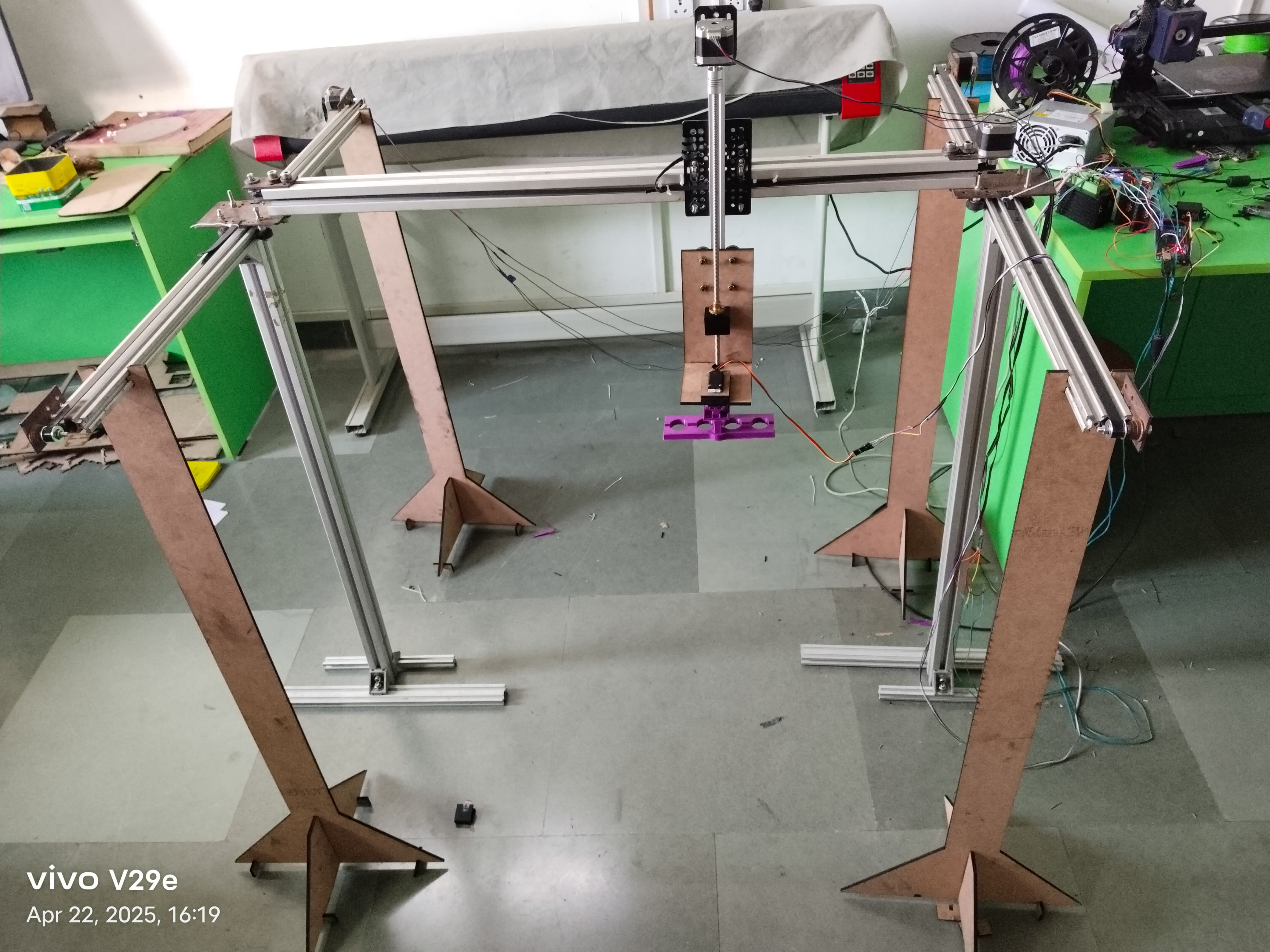
The image shows a lead screw-based vertical linear motion setup, commonly used for precise Z-axis movement. The MDF platform is mounted on a brass lead screw nut, and the screw is guided vertically. A small servo motor is also mounted on the platform, connected to what appears to be a 3D-printed gripper or holder, possibly used for picking or positioning objects.
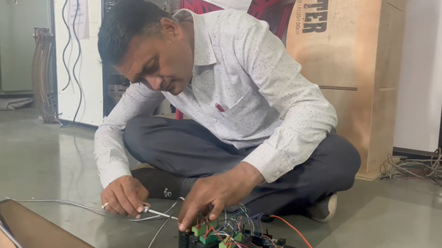
In the next step, I proceeded with the electrical wiring, including the connection of the servo motor and stepper driver for the Z-axis lead screw mechanism. This setup enables vertical motion and controlled gripping action as part of the automated system.
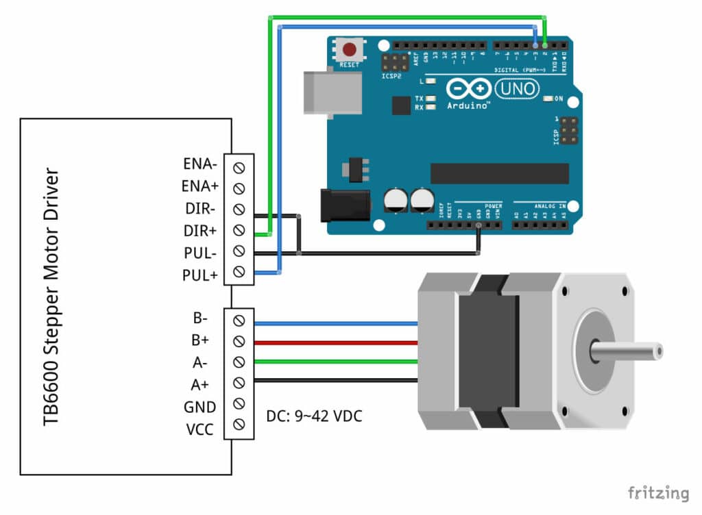
This image shows a wiring diagram for a single stepper motor using a TB6600 stepper motor driver and an Arduino UNO.
Electrical Connection Step
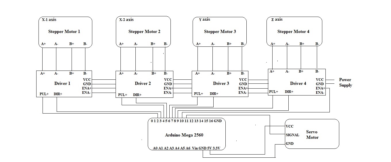
In the next step, I began the electrical connections for the automated system, as shown in the schematic. The system includes:
Four stepper motors controlling the X1, X2, Y, and Z axes.
Each stepper motor is connected to a dedicated driver module (Driver 1 to Driver 4), with standard A+/A– and B+/B– coil wiring.
Pulse (PUL+) and direction (DIR+) signals from each driver are routed to specific digital I/O pins of the Arduino Mega 2560.
Enable (ENA+) lines for all drivers are powered through a common control signal and a shared ground.
All drivers are powered from a centralized DC power supply, ensuring sufficient current delivery for the motors.
Additionally, a servo motor is interfaced with the Arduino using three connections:
VCC (from Arduino 5V)
Signal pin (from digital I/O)
GND (common ground)
As all the mechanical and electrical connections are completed, the project is now ready for programming.
Programe Code for project
#include < Servo.h >
// Stepper Motor Pin definitions
const int stepPinX1 = 3;
const int dirPinX1 = 2;
const int stepPinX2 = 5;
const int dirPinX2 = 4;
const int stepPinY = 7;
const int dirPinY = 6;
const int stepPinZ = 9;
const int dirPinZ = 8;
const int enPin = 10; // Shared enable for all drivers
// Servo
const int servoPin = 11;
Servo endEffector;
// Motion parameters
const int stepDelay = 500; // microseconds between steps
void setup() {
// Stepper setup
pinMode(stepPinX1, OUTPUT); pinMode(dirPinX1, OUTPUT);
pinMode(stepPinX2, OUTPUT); pinMode(dirPinX2, OUTPUT);
pinMode(stepPinY, OUTPUT); pinMode(dirPinY, OUTPUT);
pinMode(stepPinZ, OUTPUT); pinMode(dirPinZ, OUTPUT);
pinMode(enPin, OUTPUT);
digitalWrite(enPin, LOW); // Enable drivers
// Servo setup
endEffector.attach(servoPin);
endEffector.write(0); // Start at 0°
}
void loop() {
// 1. Y forward
setDirectionY(false);
moveY(1000);
delay(1000);
// 2. X1 & X2 forward
setDirectionX(false);
moveX(2000);
delay(1000);
// 3. Z down
setDirectionZ(false);
moveZ(500);
delay(1000);
// 4. Servo actuate
endEffector.write(45);
delay(1000);
// 5. Z up
setDirectionZ(true);
moveZ(500);
delay(1000);
// 6. Y reverse
setDirectionY(true);
moveY(1000);
delay(1000);
// 7. Z down
setDirectionZ(false);
moveZ(500);
delay(1000);
// 8. Servo diactuate
endEffector.write(0);
delay(1000);
// 9. Z up
setDirectionZ(true);
moveZ(500);
delay(1000);
// 10. X1 & X2 reverse
setDirectionX(true);
moveX(2000);
delay(1000);
}
// === Direction Setters ===
void setDirectionX(bool forward) {
digitalWrite(dirPinX1, forward ? HIGH : LOW);
digitalWrite(dirPinX2, forward ? LOW : HIGH); // Inverted for same movement
}
void setDirectionY(bool forward) {
digitalWrite(dirPinY, forward ? HIGH : LOW);
}
void setDirectionZ(bool down) {
digitalWrite(dirPinZ, down ? HIGH : LOW); // Assume HIGH = down
}
// === Stepper Movement Functions ===
void moveX(unsigned long duration_ms) {
unsigned long steps = (duration_ms * 1000UL) / (stepDelay * 2UL);
for (unsigned long i = 0; i < steps; i++) {
digitalWrite(stepPinX1, HIGH);
digitalWrite(stepPinX2, HIGH);
delayMicroseconds(stepDelay);
digitalWrite(stepPinX1, LOW);
digitalWrite(stepPinX2, LOW);
delayMicroseconds(stepDelay);
}
}
void moveY(unsigned long duration_ms) {
unsigned long steps = (duration_ms * 1000UL) / (stepDelay * 2UL);
for (unsigned long i = 0; i < steps; i++) {
digitalWrite(stepPinY, HIGH);
delayMicroseconds(stepDelay);
digitalWrite(stepPinY, LOW);
delayMicroseconds(stepDelay);
}
}
void moveZ(unsigned long duration_ms) {
unsigned long steps = (duration_ms * 1000UL) / (stepDelay * 2UL);
for (unsigned long i = 0; i < steps; i++) {
digitalWrite(stepPinZ, HIGH);
delayMicroseconds(stepDelay);
digitalWrite(stepPinZ, LOW);
delayMicroseconds(stepDelay);
}
}
I developed and uploaded the program using the Arduino IDE, which provided a convenient platform for writing and uploading the code.
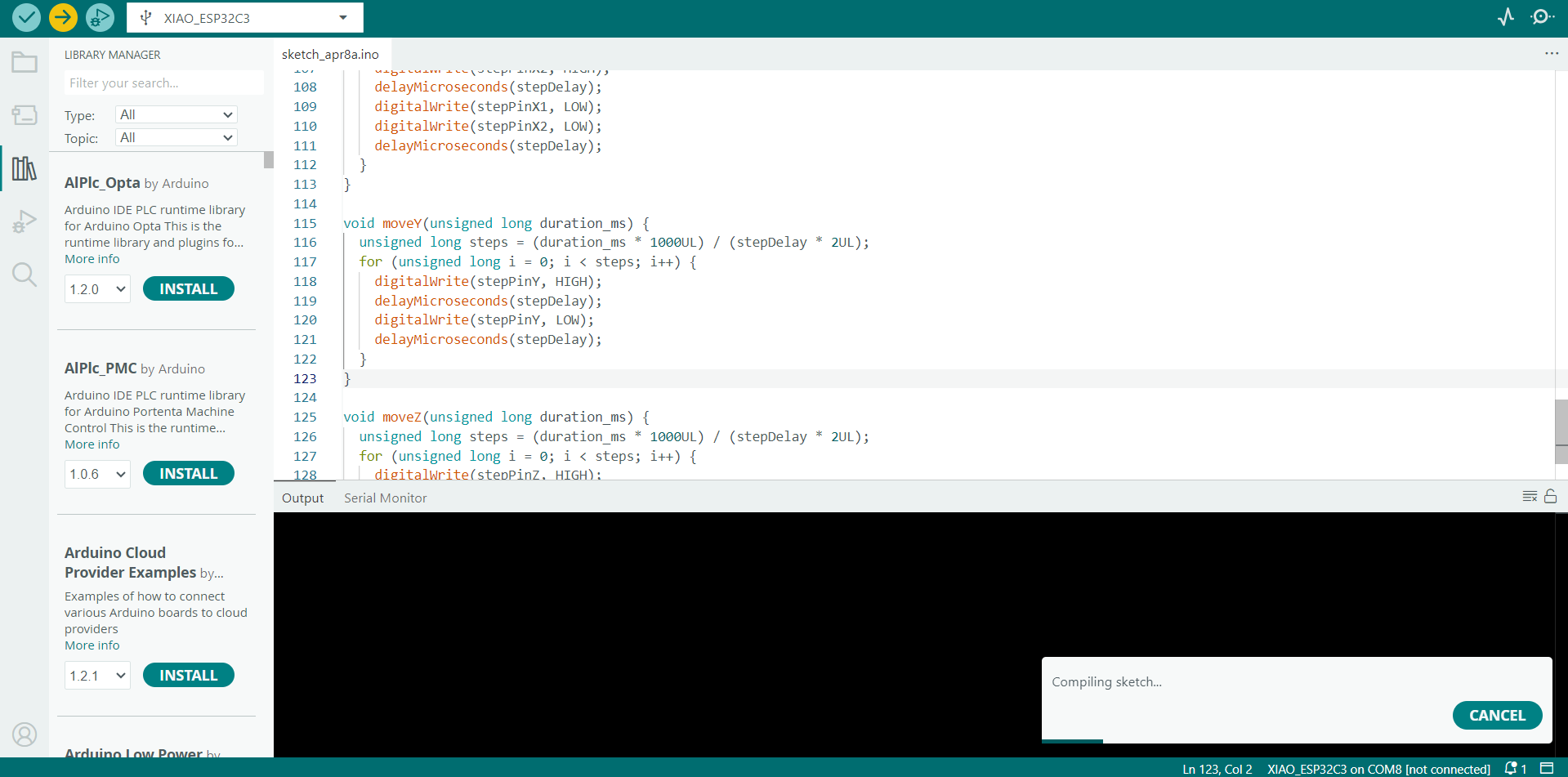
Once the code is successfully uploaded to the microcontroller through the Arduino IDE, the microcontroller immediately begins executing the instructions written in the program. These instructions control the various components connected to the board.The microcontroller reads the logic, follows the timing delays, and sends signals to the output pins as defined in the code. This automated execution ensures that the project functions without any manual intervention. As a result, the entire system starts running smoothly and performs the intended operations, such as moving motors, displaying data, or responding to sensor inputs, exactly as programmed.