Week 10. Output Devices
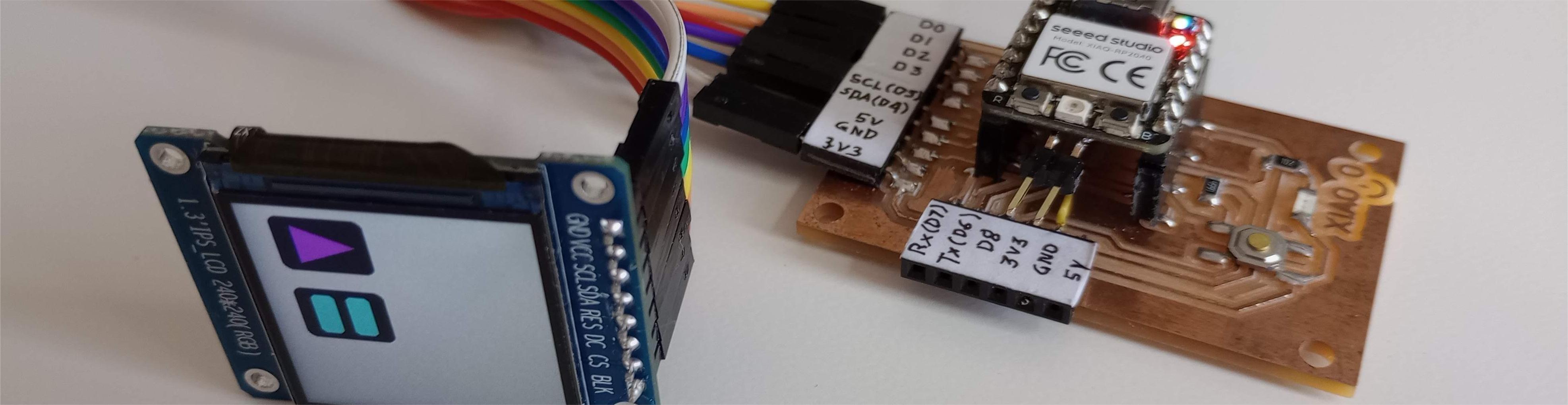
Table of Contents
- WEEKLY PLAN
- GROUP ASSIGNMENT: POWER CONSUMPTION OF OUTPUT DEVICE
- INDIVIDUAL ASSIGNMENT: OUTPUT DEVICES
- USEFUL LINKS AND RESOURCES
- FILES
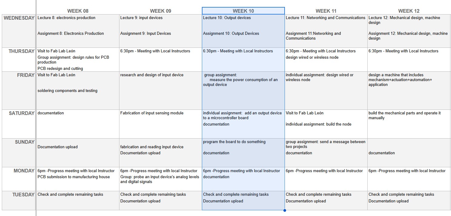
WEEKLY PLAN
Group assignment:
- Measure the power consumption of an output device.
Individual assignment:
- Add an output device to a microcontroller board you’ve designed and program it to do something.
GROUP ASSIGNMENT: OUTPUT DEVICES
This is the link to the Fab Lab León Group Assignments page. Since I am completing the group assignment on my own I left the documentation on this page.
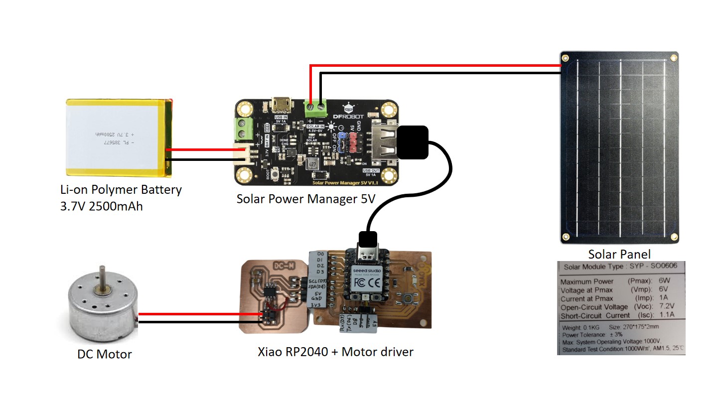
DC MOTOR POWER CONSUMPTION
To measure the consumption of a DC motor, I decided to connect a solar panel to a solar panel control board and a battery. This will supply power to the Xiao RP2040 development board (fabricated during electronics production week) and the DC motor connected via a driver board (designed and fabricated in the individual assignment).
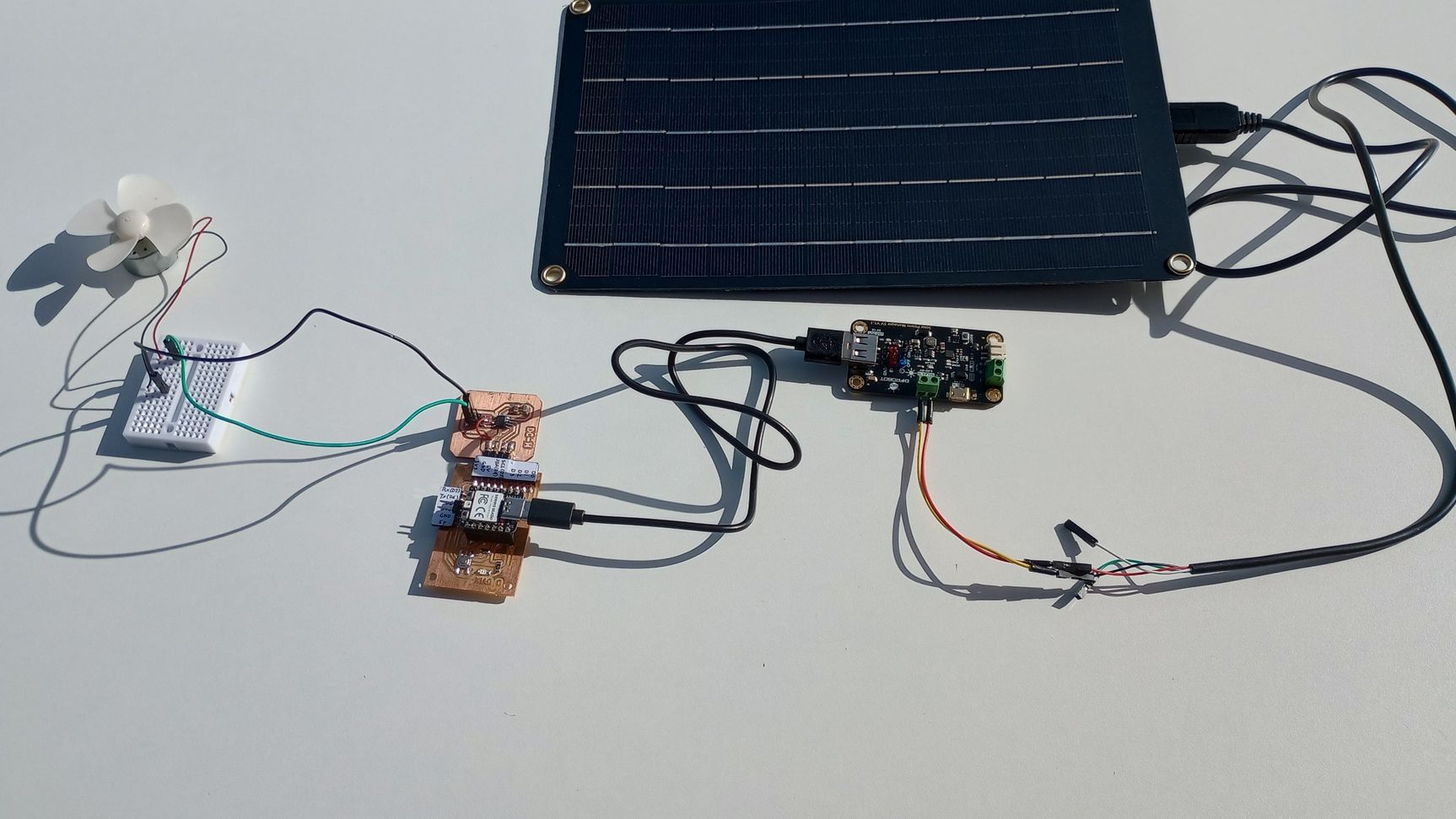
I started by using the multimeter to measure the voltage and current provided by the solar panel.
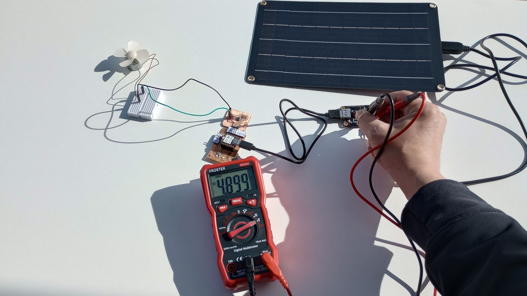
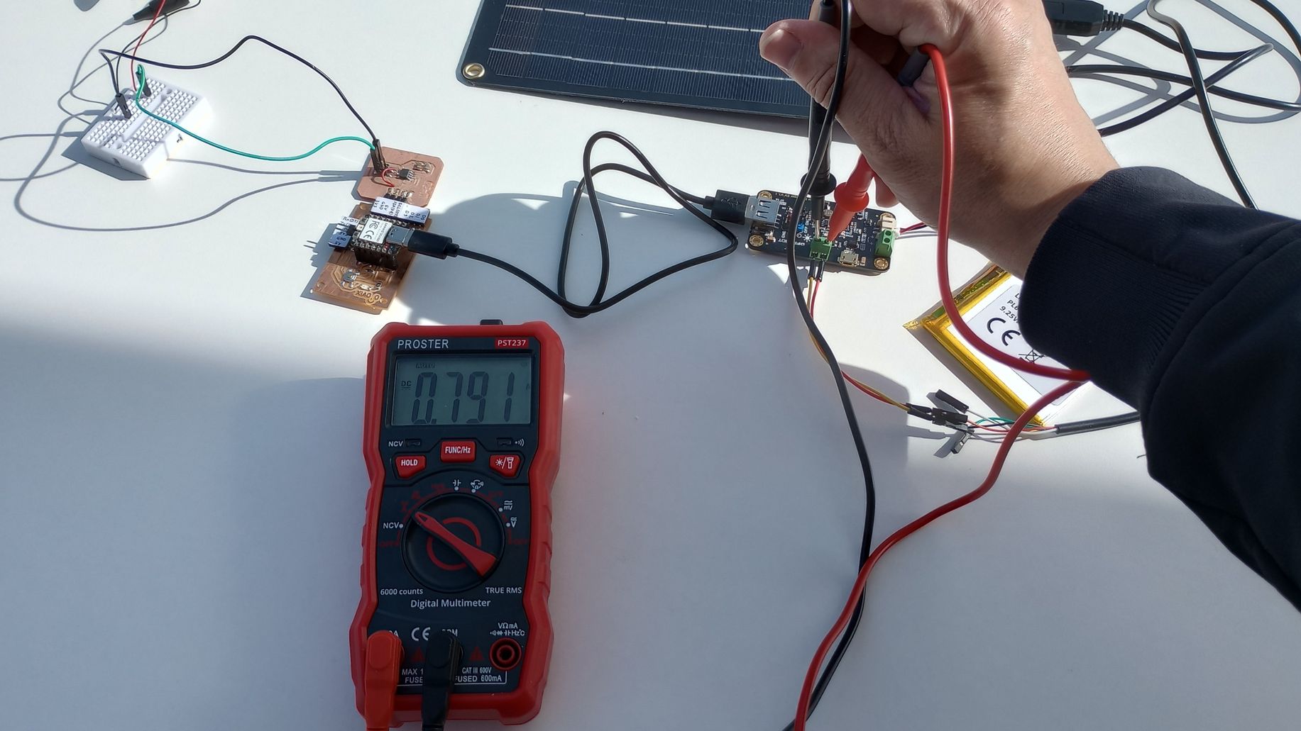
The voltage measured in the solar input connection in the control board was 4.899v and the current 0.791 Amps.
To measure the power consumption of the DC motor, I use the multimeter to measure the voltage and current.
As shown in the image the voltage supplied by the driver board to the motor is 2.927v.
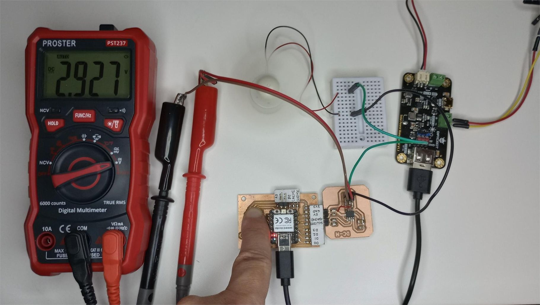
To measure the current flowing through the motor I insert the multimeter in series with the motor's power supply. To measure current the red probe of the multimeter must be inserted in the 10A terminal and the selector in the current reading function.
The maximum current measured was 0.048A.
Therefore, if the motor is supplied with 2.927v and draws 0.048A, then the power consumption (P = V x I) is 2.927V x 0.048A =0.14 Watts.
Top
INDIVIDUAL ASSIGNMENT: OUTPUT DEVICES
DC MOTOR CONTROL
DC motors are widely used in various electronic projects. In this assignment, I am exploring how to control a DC motor by designing and fabricating a driver circuit, using the microcontroller development board that I created during Electronics Production week.
Following Adrián's recommendation, I decided to use the Toshiba TB67H451FNG brushed motor driver. A DC motor driver is essential for controlling a DC motor with a microcontroller, as it manages power requirements, enables direction and speed control, and provides necessary protection for both components.
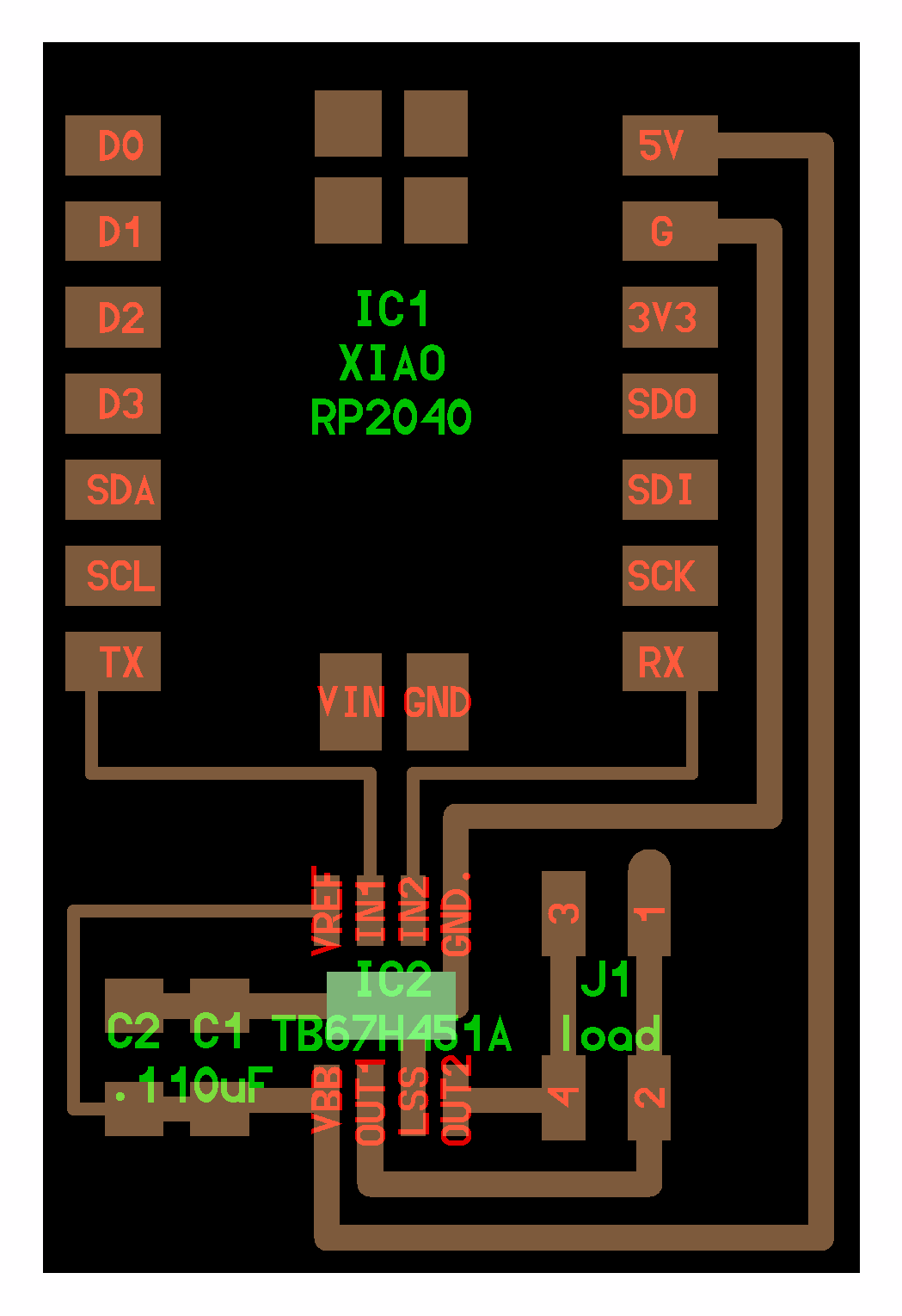
Using the DC motor driver boards designed by Adrián and Neil as references, I created a schematic in KiCad 9.0, using the Fab Academy library to incorporate SMD components.
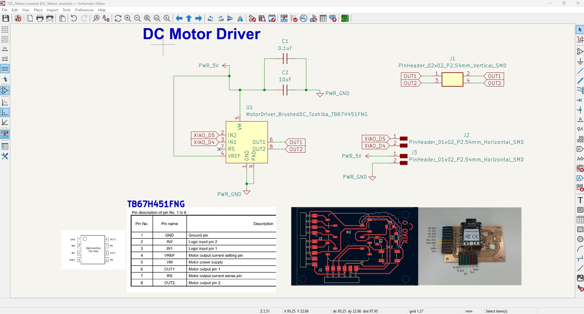
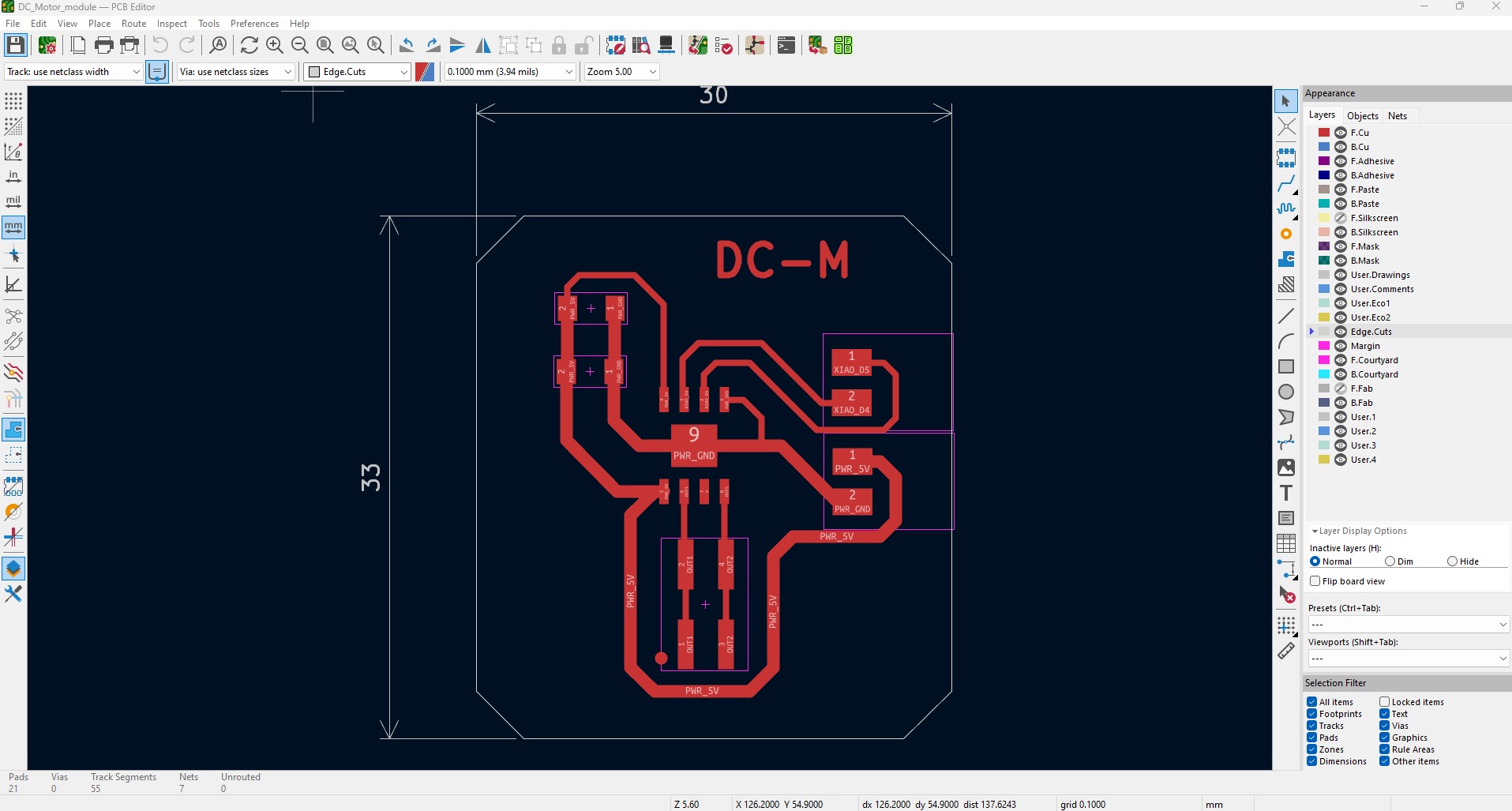
With the schematic completed, I can now generate the PCB tracks for manufacturing. This board will be powered by 5V, so the GND and 5V tracks are thicker (0.8mm) than the other tracks.
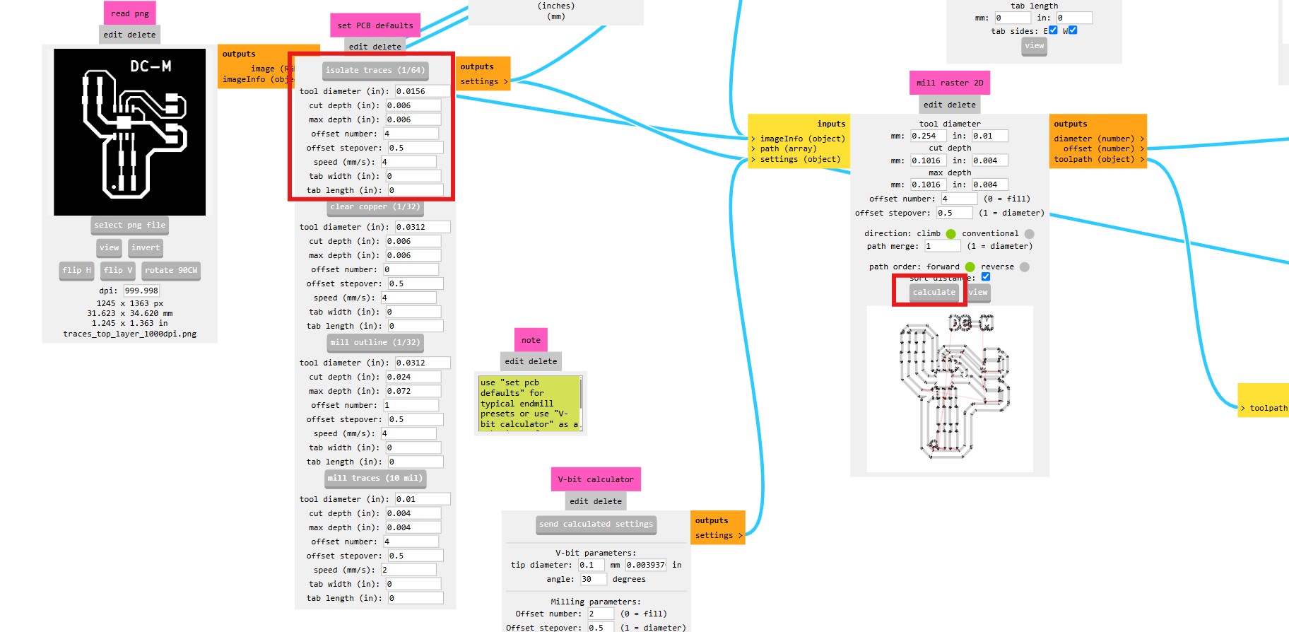
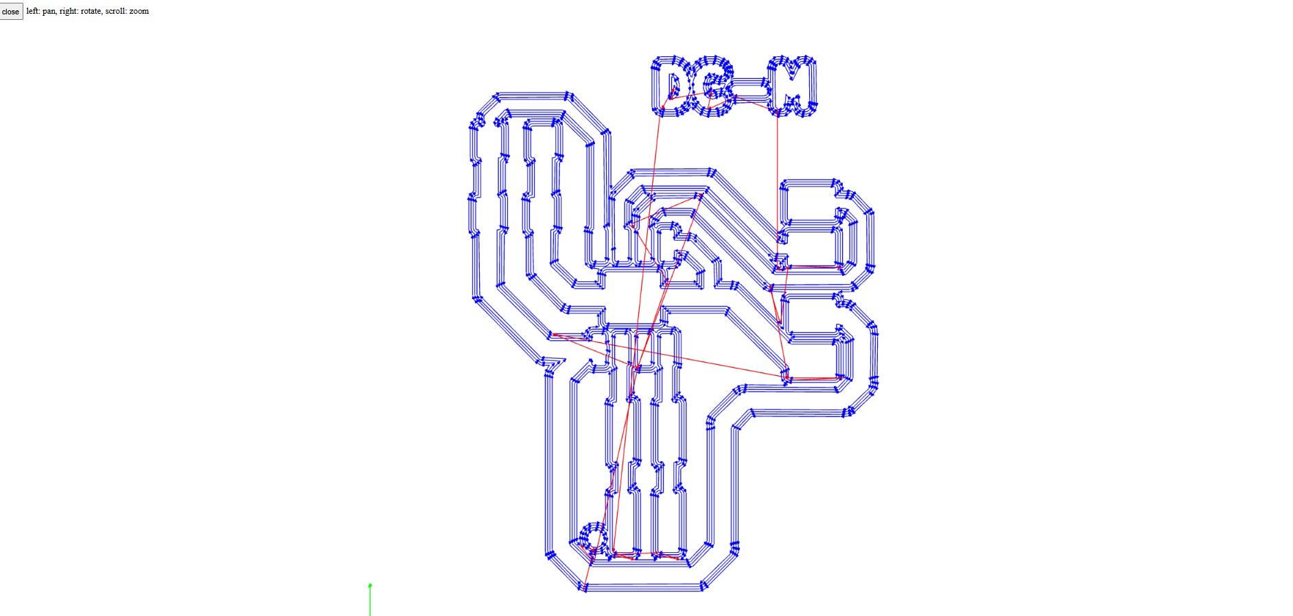
Once the design work is completed in KiCad9.0, I export the Gerber files so I can convert them into .png files using Gerber2PNG application.

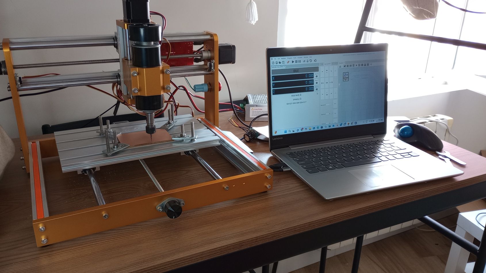
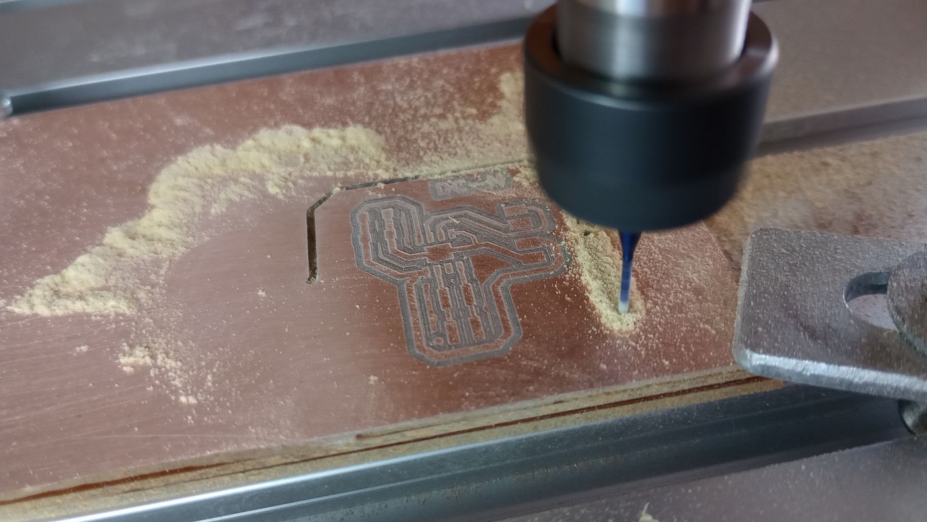
I use MODS.org to generate the traces that I send to the CNC milling machine, a Lunyee 3018 Pro Max, which was kindly lent to me by the team at Fab Lab León.
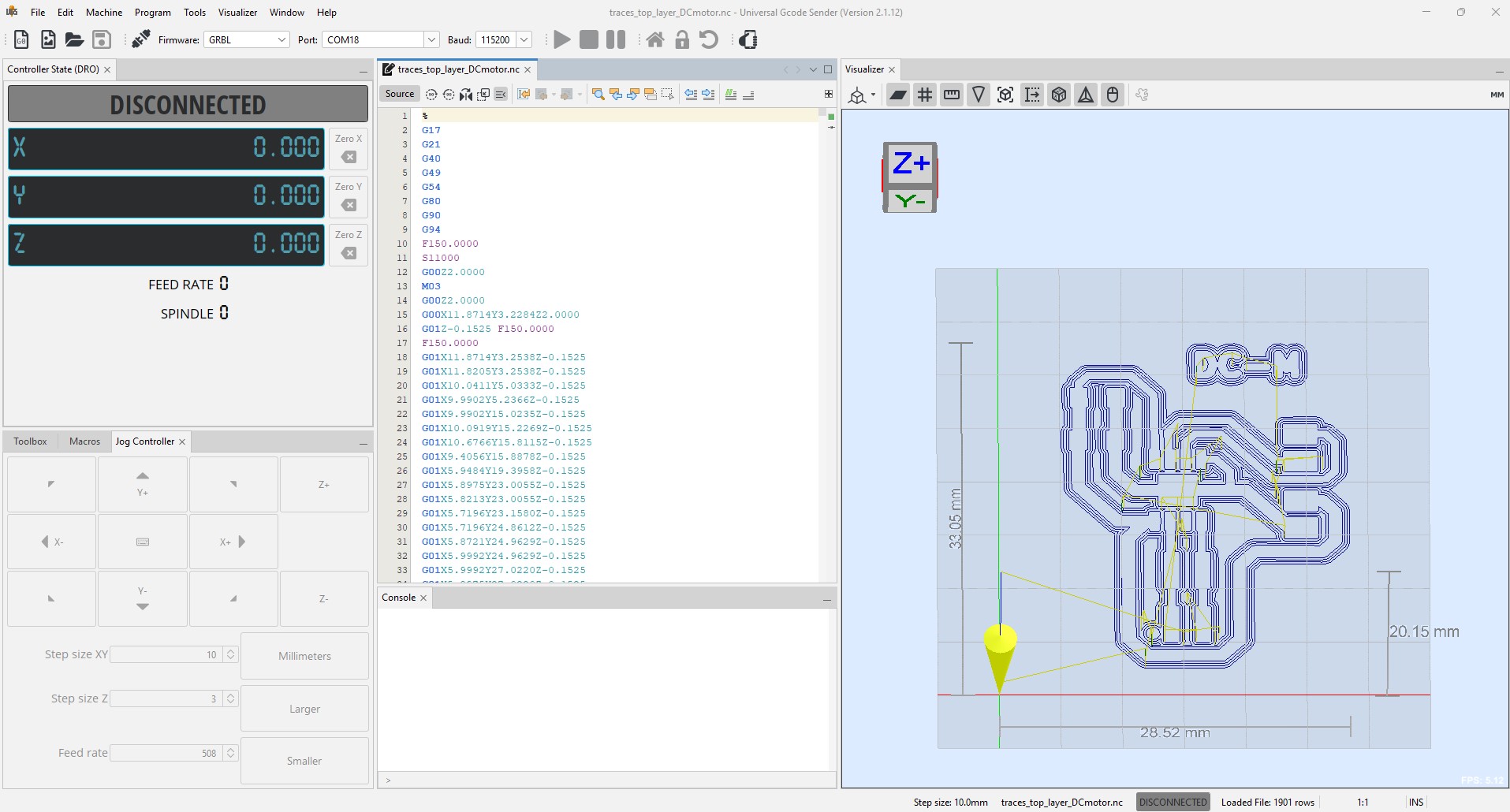
Next, I import the files generated in MODS.org into the UGS CNC control software. I then fit a 0.25R conical milling tool and set the XYZ zero.
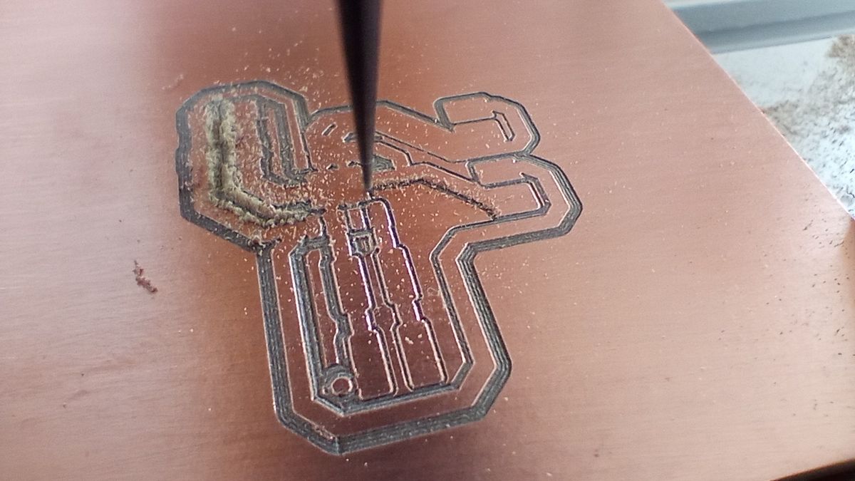
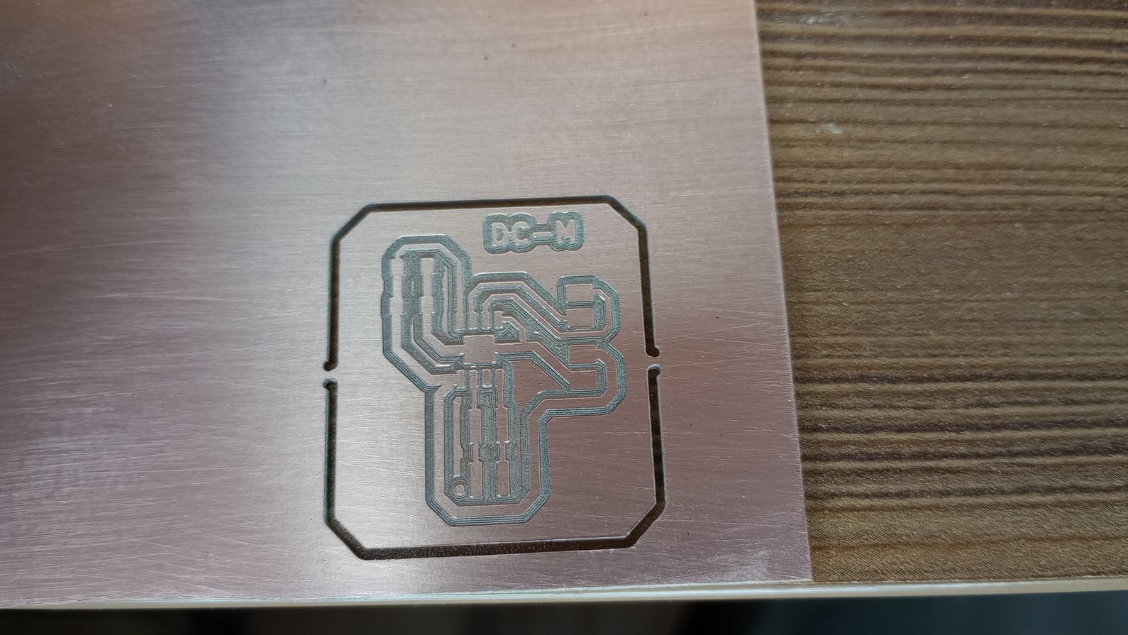
After the traces are milled, I change the tool to a straight end mill, set the Z0 agian, and I send the outline to be cut.
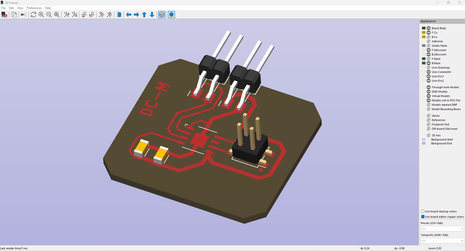
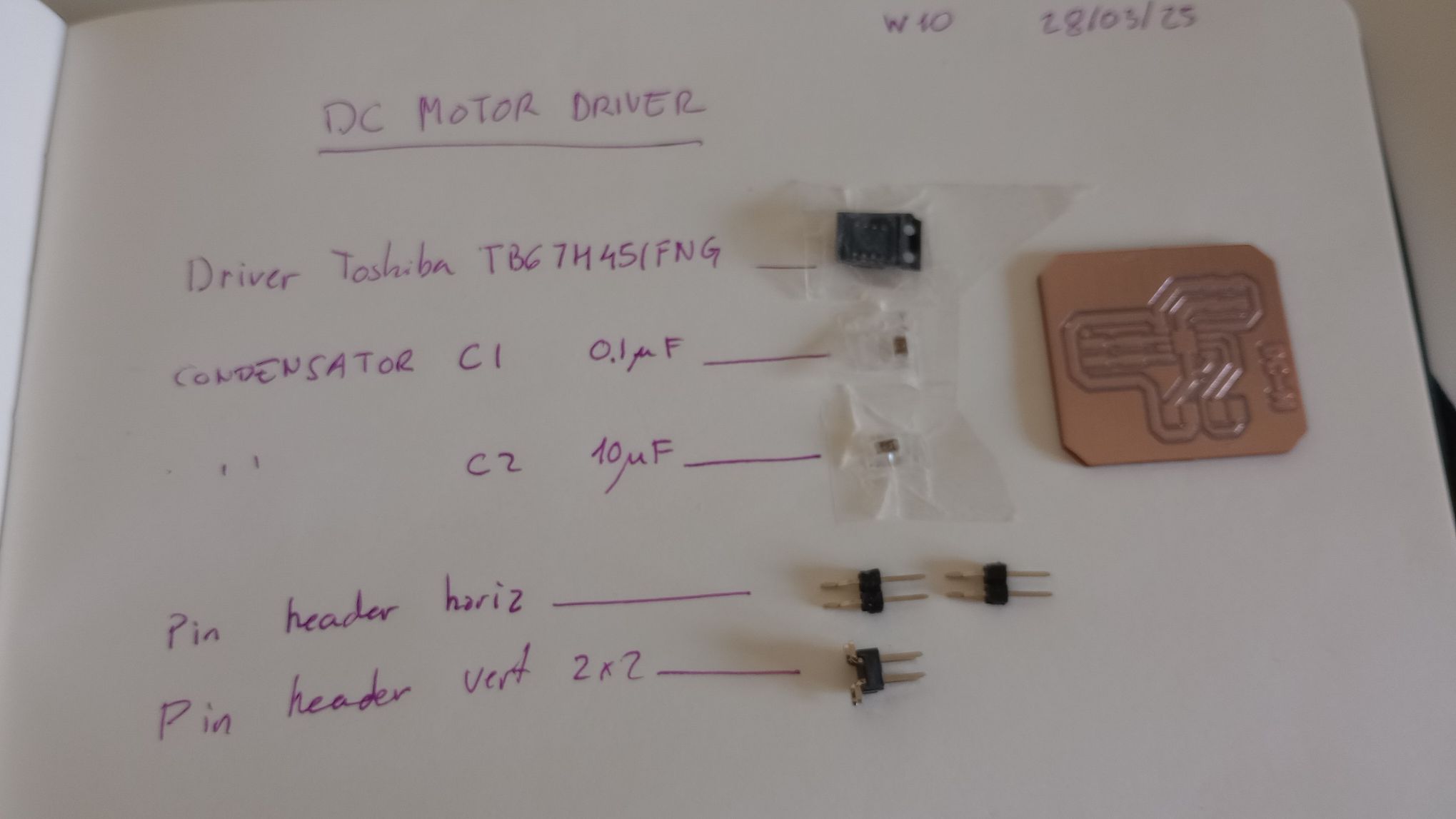
These are the components I´ll be using to populate the board.
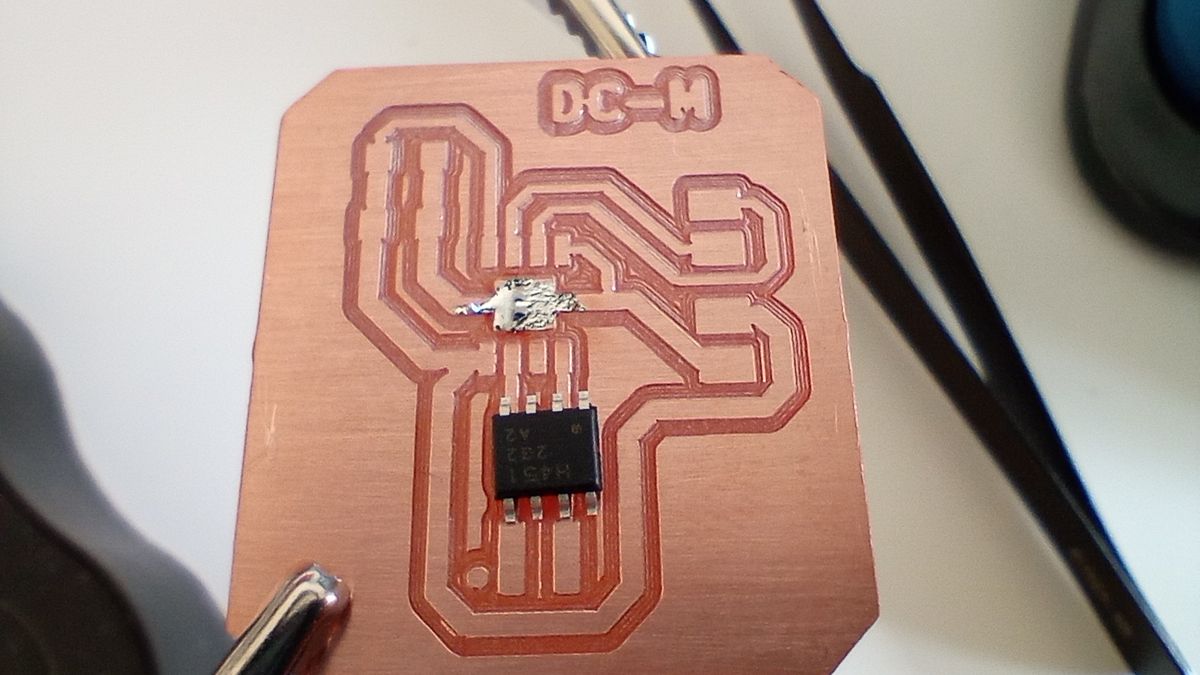
The driver chip has a GND pad at the bottom that also helps to dissipate heat. I start by adding a bit of solder on this pad to fix the chip before proceeding to carefully solder each leg.
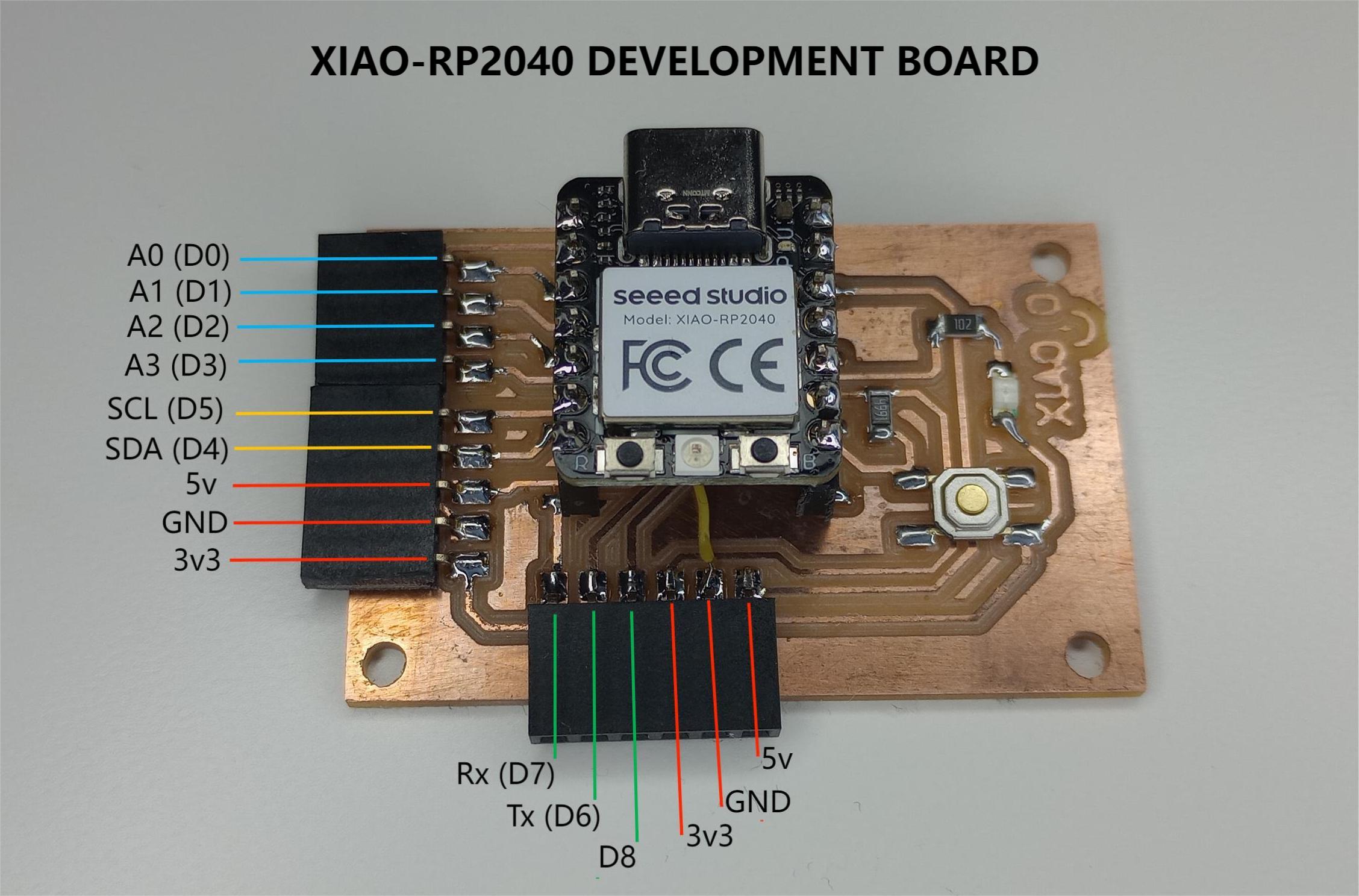
To test the DC driver board with a Dc motor, I am using the XIAO Development Board I fabricated during week 08.
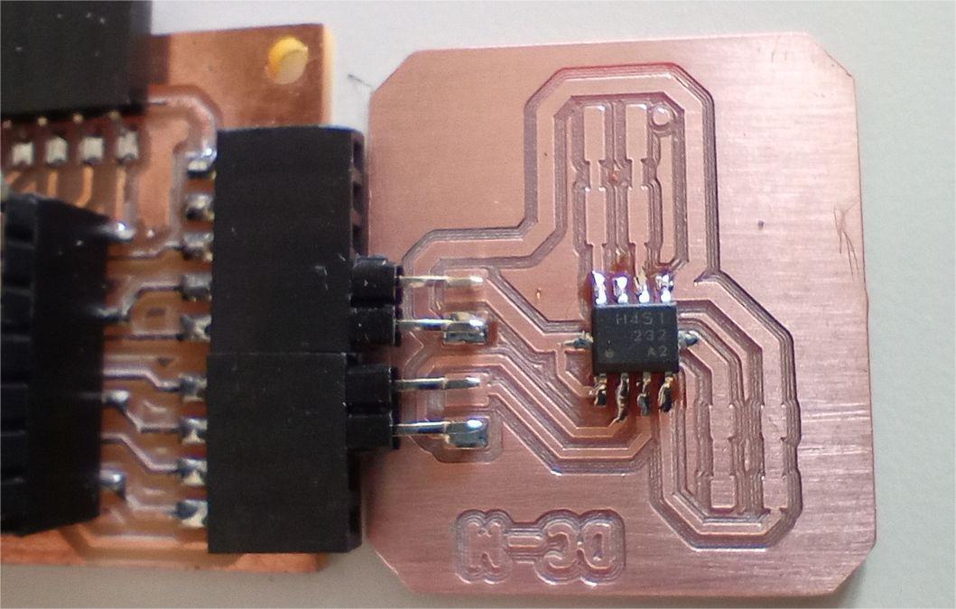
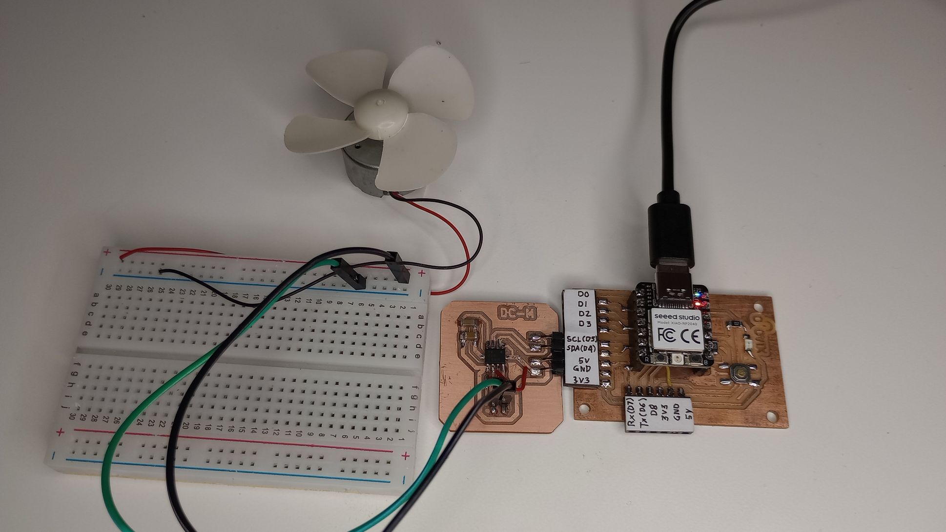
The DC motor driver connects directly to the Xiao board, and as shown in the following image, I have connected a DC motor to the output pins of the driver board.
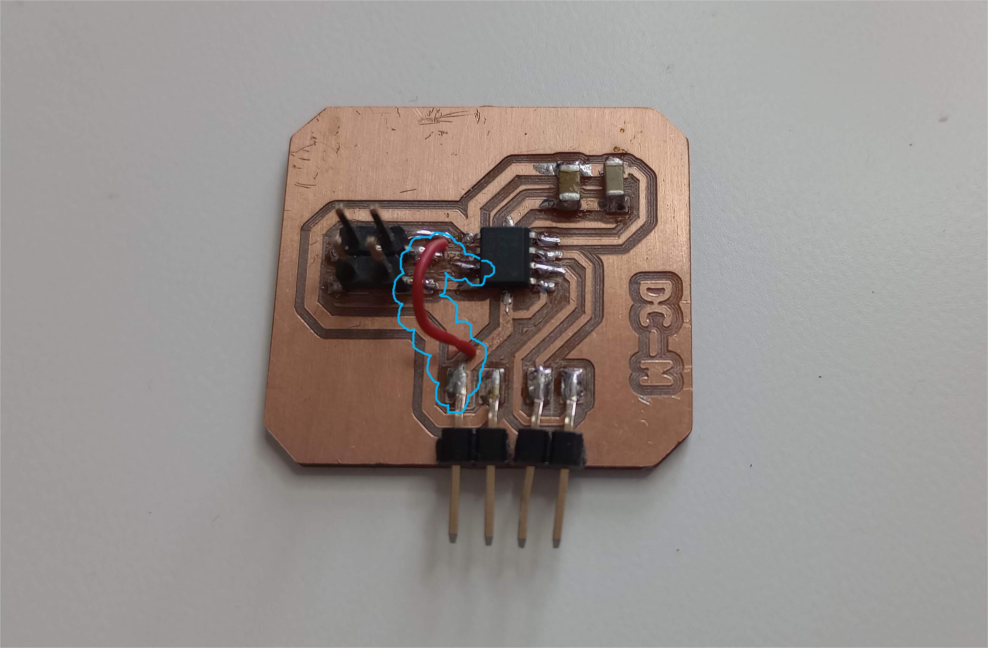
After trying different programs to control the motor, I realised it wasn't responding. I began a series of troubleshooting steps, using a multimeter to check continuity and voltage at different points. Everything seemed fine except for the output pins, which were delivering less than 3 volts.
Next, I examined the soldering and the circuit. Upon inspecting the chip, I noticed that the RS pin was not connected to the circuit. After reviewing the TB67H451FNG datasheet, I found that this pin should be connected to ground (GND). I then used a wire to connect the RS pin (the motor output current sense pin) to GND, and that resolved the issue.
To control the DC Motor I start by using Neil´s program hello.TB67H451.RP2040.ino
DC-Motor_control.ino
//DC-Motor_control
//XIAO RP2040
//based on hello.TB67H451.RP2040.ino by Neil Gershenfeld
//
uint32_t duty_min = int(0.65*65535);
uint32_t duty_max = int(0.75*65535);
uint32_t delay_ms = 500;

void setup() {
  analogWriteFreq(100000);
  analogWriteRange(65535);
  }
void loop() {
  analogWrite(D4,0);
  analogWrite(D5,duty_min);
  delay(delay_ms);
  //
  analogWrite(D4,duty_min);
  analogWrite(D5,0);
  delay(delay_ms);
  //
  analogWrite(D4,0);
  analogWrite(D5,duty_max);
  delay(delay_ms);
  //
  analogWrite(D4,duty_max);
  analogWrite(D5,0);
  delay(delay_ms);
  }
Next, I try Adrian's program Arduino Hello Motor to control a DC motor with the button of the development board.
DCmotor_driver_button.ino
//DCmotor_driver_button.ino
//Based on program by Adrián Torres from Fab Lab León to control DC Motor
const int pushbuttonPin = D9;     // button
const int motor1Pin = D4;      // H-bridge pin (in2)
const int motor2Pin = D5;      // H-bridge pin (in1)

void setup() {
    pinMode(pushbuttonPin, INPUT);
    // set H-bridge pins as outputs:
    pinMode(motor1Pin, OUTPUT);
    pinMode(motor2Pin, OUTPUT);
  }
void loop() {
    // if button is pressed, (=LOW because the unpressed 'pulled up' state is HIGH)
  if (digitalRead(pushbuttonPin) == LOW) {
      analogWrite(motor1Pin, 127); // set pin 1 of the H-bridge to 50% using PWM
      analogWrite(motor2Pin, 0);   // set pin 2 of the H-bridge to low state
    }
     // if button is not pressed, the motor will stand still
  else
      {
      digitalWrite(motor1Pin, LOW);   // set pin 1 of the H-bridge low
      digitalWrite(motor2Pin, LOW);   // set pin 2 of the H-bridge low
      }
  }
LCD DISPLAY
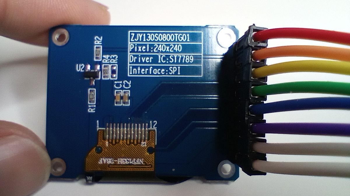
Another output I am trying with the Xiao RP2040 development board is a 1.3 inch LCD display Module 240x240 pixels - 3.3V. This display based on the ST7789 driver.
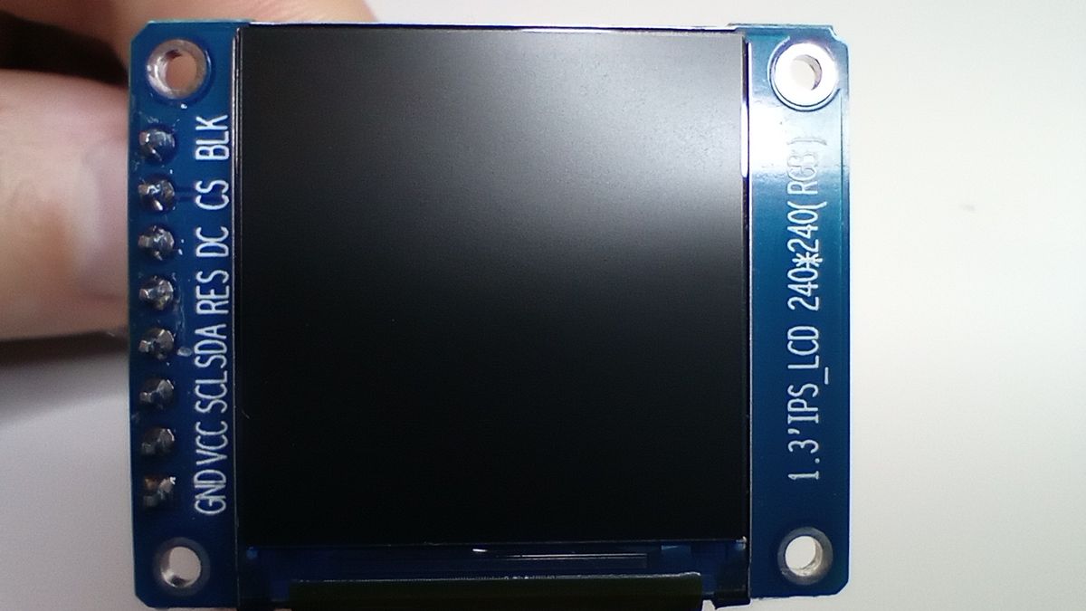
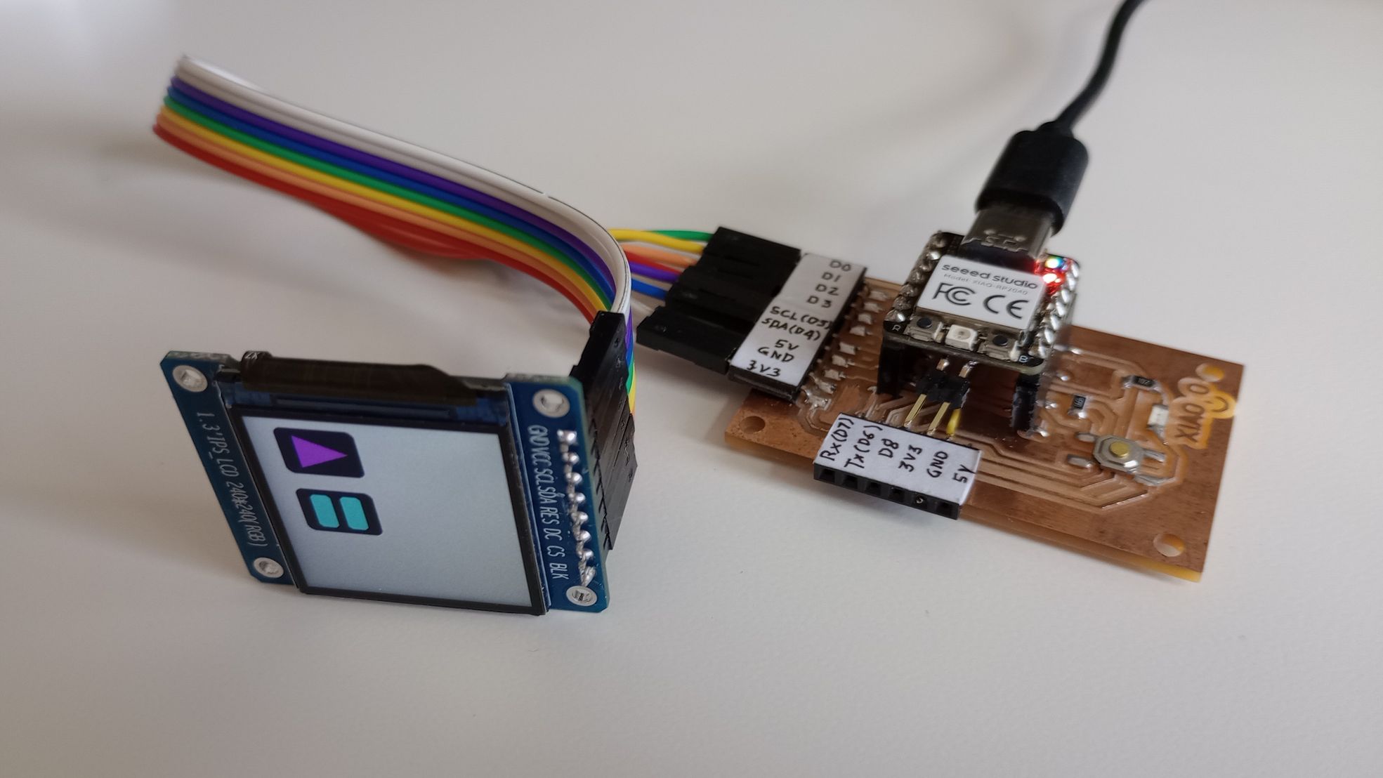
Interface of display with Xiao RP2040
|
SYMBOL |
DESCRIPTION |
PIN on XIAO RP2040 |
|
VCC |
Power (3.3V/5V input) |
3v3 |
|
GND |
Ground |
GND |
|
SDA |
Serial Data Input |
D4 |
|
SCL |
SPI Serial Clock |
D5 |
|
CS |
Chip selection, low active |
D1 |
|
DC |
Data/Command selection (high for data, low for command) |
D2 |
|
RES |
Reset, low active |
D0 |
|
BLK |
Backlight on/off |
D3 |
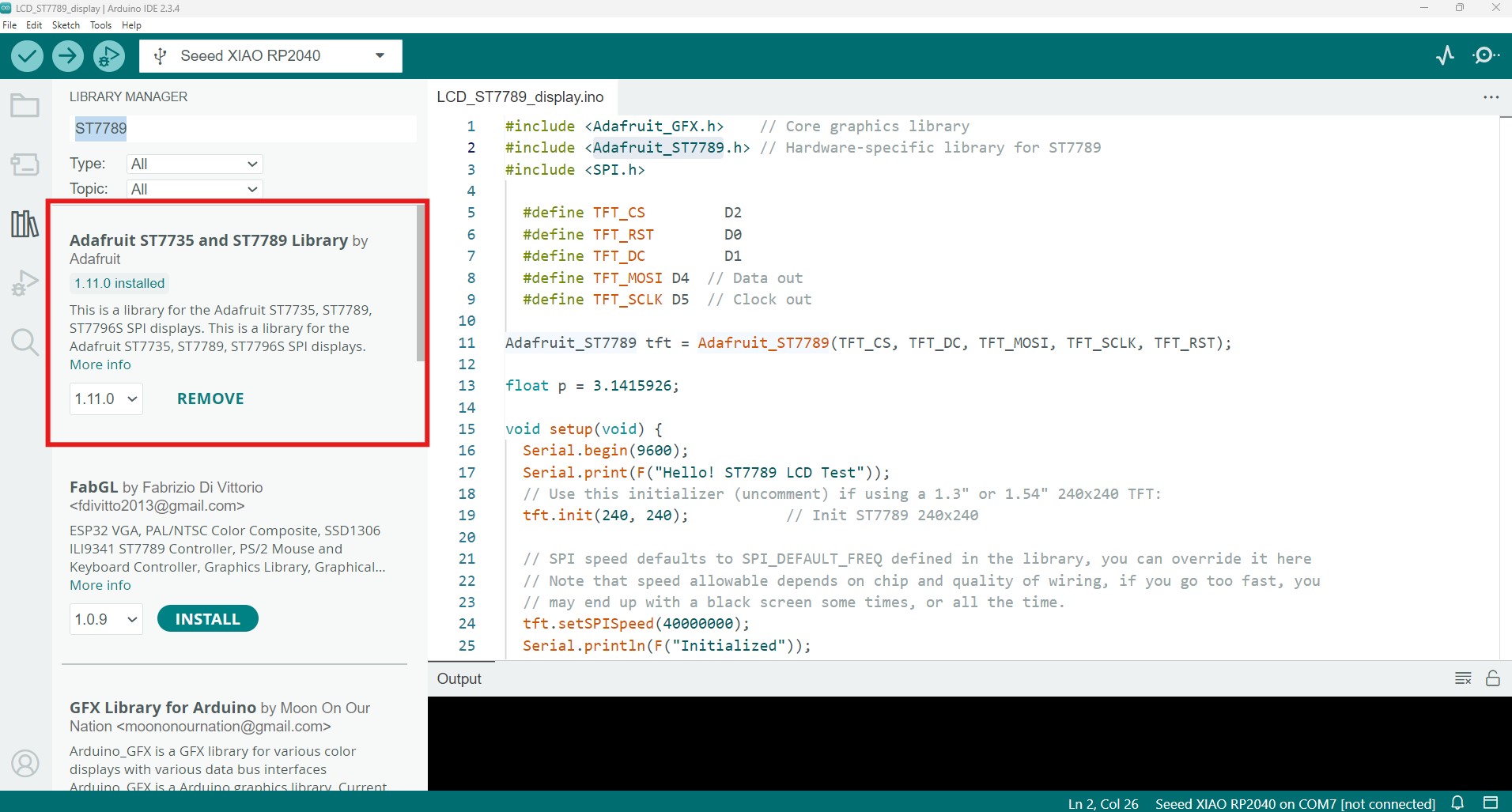
In Arduino IDE I add the library to for the ST7789 driver from Adafruit and I use their graphicstest_st7789.ino as the base to make a program that runs in the Xiao RP2040.
USEFUL LINKS AND RESOURCES
FILES
KiCad9.0 Schematic and PCB of DC Motor driver: DC_Motor_module.zip
DC Motor driver - traces and outline png: DC_motor_driver_png_files.zip
Arduino program to control DC motor : DCmotor_control.ino
Arduino program to control DC motor with button : DCmotor_driver_button.ino
Arduino program to control LCD display ST7789 : LCD_ST7789_display.ino
Top