Week 03. Computer-Controlled Cutting
Table of Contents
- WEEKLY PLAN
- GROUP ASSIGNMENT: LASER CUTTER PARAMETERS
- INDIVIDUAL ASSIGNMENT: PARAMETRIC CONSTRUCTION KIT
- VINYL CUTTING
- USEFUL LINKS AND RESOURCES
- FILES
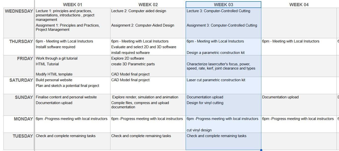
WEEKLY PLAN
Group assignment:
- Lab's safety training
- Characterize laser cutter's focus, power, speed, rate, kerf, joint clearance and types.
- Document work to the group work page and reflect on your individual page what you learned.
Individual assignment:
- Design, lasercut, and document a parametric construction kit, accounting for the laser cutter kerf, which can be assembled in multiple ways.
- Cut something on the vinyl cutter.
GROUP ASSIGNMENT: LASER CUTTER PARAMETERS
As I am a distance learner at the Fab Lab León, I am completing this part of the assignment on my own and with the laser cutter I have access to.
The model I am characterizing is the AEON NOVA 14 Elite. This is a 100W CO2 laser engraving and cutting machine with a working area of 1400x900mm, scan speeds of 1200mm/sec.
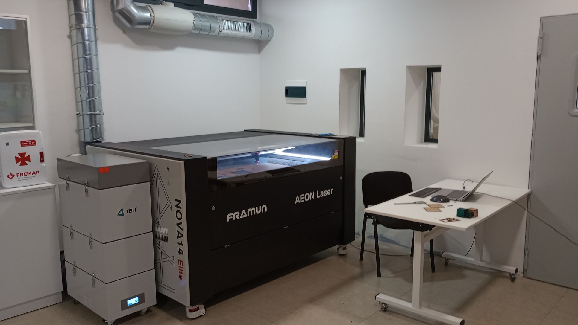
The manufacturer lists a detailed technical specifications for the Elite series on their website. Here I have listed the most relevant specs for the model we have.
| AEON NOVA 14 Elite | |
|---|---|
| Working Area | 1400x900mm |
| Laser power | 100W CO2 Glass Tube |
| Electric Up&Down | 200mm Adjustable |
| Air Assist | 105W Built-In Air Pump |
| Blower | 550W Built in Exhaust Fan |
| Cooling | Built-in 5200 Chiller |
| Engraving Speed | 1200mm/s |
| Cutting Thickness | 0-30mm(depends on different materials ) |
| Locating Precision | 0.01 mm |
| Engraving Software | RDWorks / LightBurn |
| Graphic Format Supported | AI/PDF/SC/DXF/HPGL/PLT/RD/SCPRO2/SVG/LBRN/BMP/JPG/JPEG/PNG/GIF/TIF/TIFF/TGA |
The extraction system includes a 280m3/h carbon filter unit made by TBH (link) and local air extraction.
Safety measures when using a laser cutting machine
Check Cutting files:
- Ensure that the work to be cut has been checked for duplicated lines and that the correct settings have been applied
Ensure Proper Ventilation:
- Fume Extraction System: Use a fume extractor or ventilation system to remove harmful fumes, gases, and smoke generated during the laser cutting and engraving process.
Properly Handle and Store Materials:
- Use the Right Materials: Only use materials recommended for laser cutting and engraving to prevent harmful fumes or fire risks.
- Avoid Reflective Materials: Never cut or engrave highly reflective materials, such as mirrors or metals, as they can reflect the laser and cause injury or damage.
Adjust and Test Settings Before Full Operation:
- Test Cuts: Before starting a full job, always run a test cut or engraving on a scrap piece of material to ensure the settings are correct.
- Laser Focus: Ensure the laser is properly focused and aligned before starting the cutting or engraving process.
Never Leave the Machine Unattended:
- Monitor the Cutting Process: Always stay nearby while the laser cutter or engraver is in operation to quickly address any malfunctions or fires.
- Emergency Stops: Be familiar with emergency shutdown procedures in case of an accident or malfunction.
Keep the Work Area Clean and Organized:
- Clear Flammable Materials: Ensure that the area around the machine is free from flammable or combustible materials.
- Emergency Stops: Ensure that the laser working area is clean and remove any debris after the cutting operation
Be Aware of Fire Hazards:
- Keep Fire Extinguishers Nearby: Always have a fire extinguisher rated for electrical and material fires within reach.
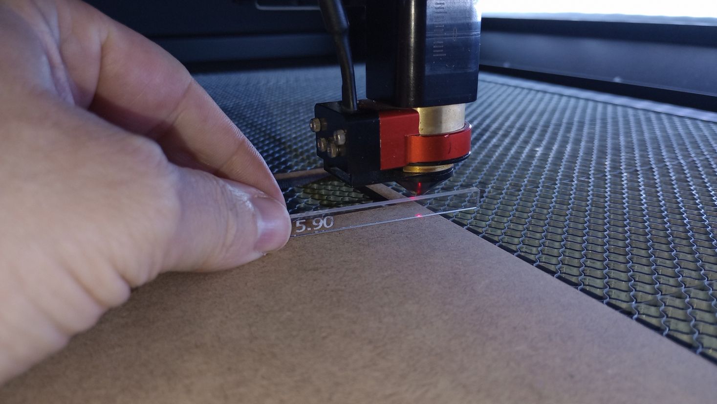
Focusing the laser beam
Focusing the laser beam is essential for reducing the kerf and increasing cutting power. There are two methods to achieve this: manual focusing and autofocus. The manual method involves using a gauge, specifically a 5.9mm high piece of acrylic.
This focusing tool is placed on top of the material to be cut, and the table is gradually raised until the gauge touches the nozzle.
With the integrated autofocus mechanism, the material is positioned beneath the laser head. The bed automatically rises until a built-in probe is activated, at which point the bed lowers by the focusing distance.
Power, Speed and Rate
The output Power and head Speed are the most important settings for laser cutters and they are set as percentage between 0 and 100%.
Laser manufacturers usually provide a list of power and speed parameters for various materials and thicknesses. However, it is often necessary to fine-tune these values by experimenting with different materials and thicknesses. Over time, this approach helps build your own library of parameters.
I have decided to determine the lowest power and speed settings required to effectively cut and engrave the single-flute cardboard 3.8 mm thick I have in stock.
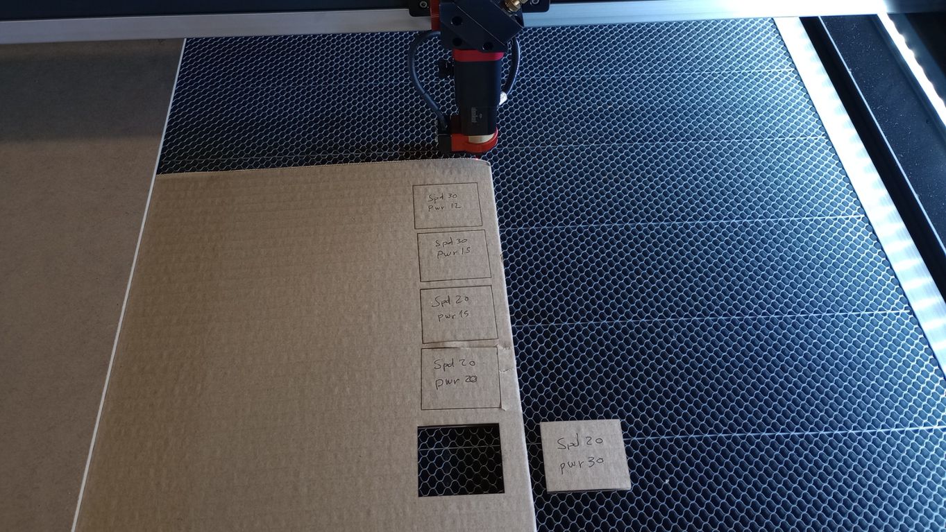
After several tests with cutting, engraving and marking I obtain the following results:
- Cutting: Spd 20/ Pwr 30
- Engraving: Spd 200/Pwr 30
- Marking: Spd 80/Pwr 12
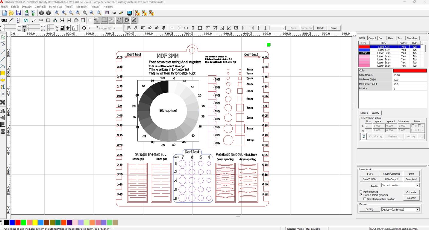
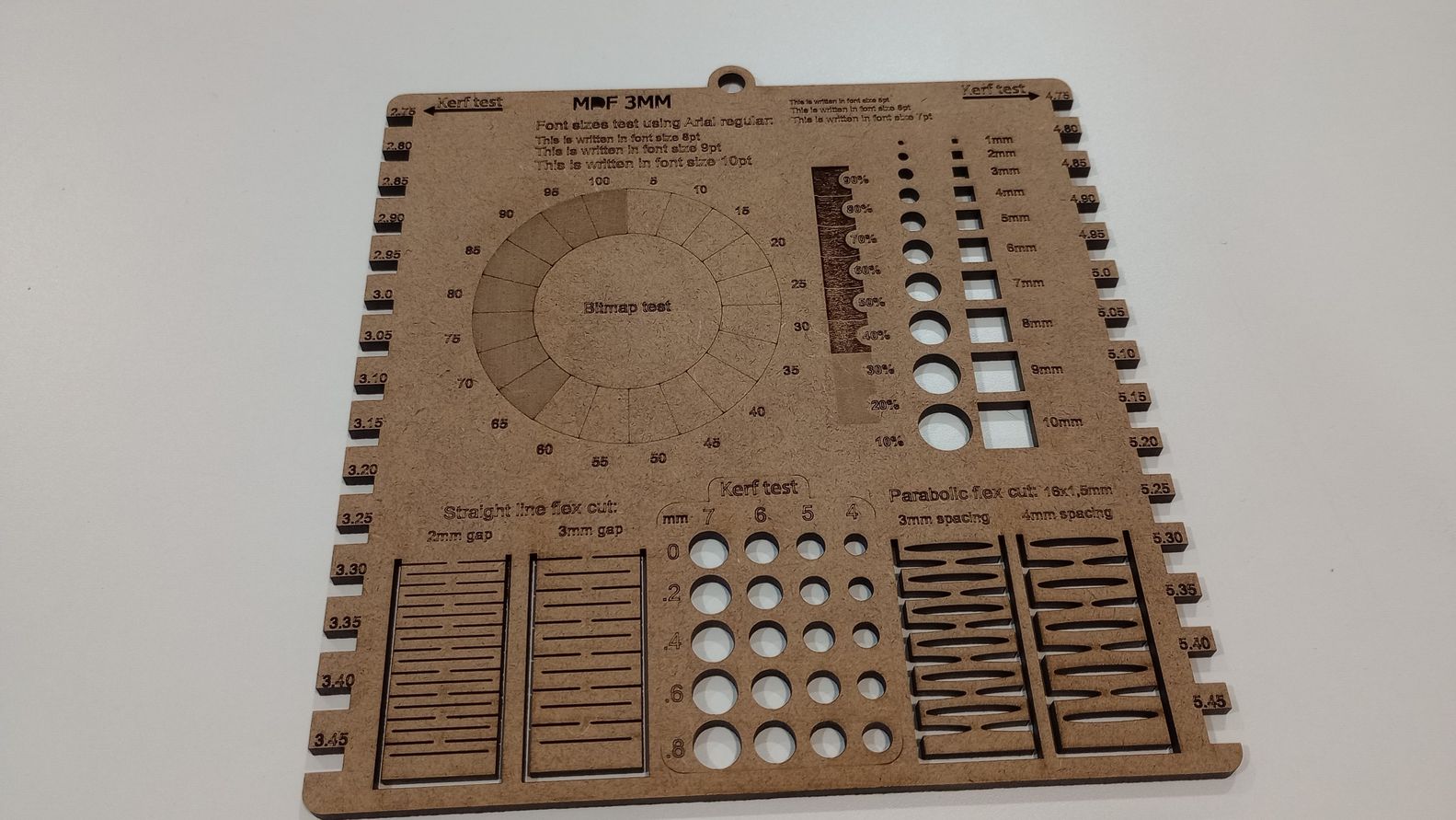
Additionally , I downloaded ( link) and modified a material testing card for laser cutters, which I used to demonstrate various engraving, cutting, and kerf options for 3mm MDF.
Calculating Kerf and its allowance
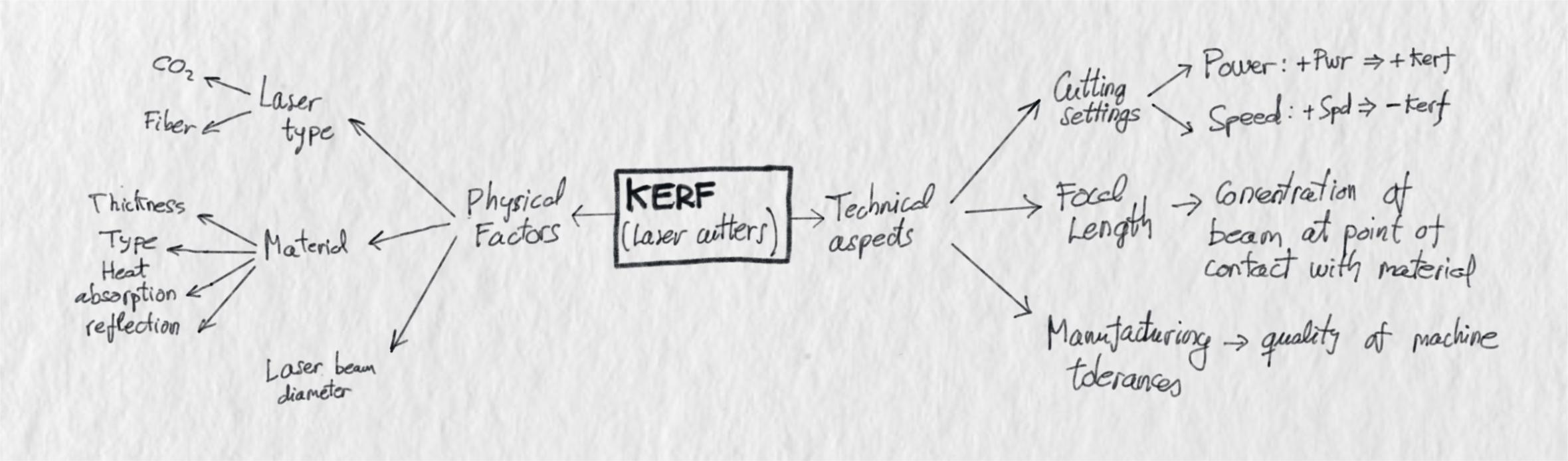
In this post by Cameron Lee, the term "kerf" refers to the amount of material removed by a laser beam during the cutting process of laser cutters. Understanding the kerf value is crucial for achieving accuracy and precision, particularly when working with assemblies. Several factors can influence the dimensions of the kerf, including the machine's tolerance and the properties of the material, as illustrated in this diagram I made based on C. Lee´s post.
Kerf calculation: Method 1
To calculate the kerf of the laser machine in our workshop, I begin by designing a kerf calculation tool made up of 10 rectangles, each 10mm wide. This kerf calculation is specifically for MDF 3mm thick.


Results:
- Overall real measurement= 99.28 mm
- Total gap= 100-99.28= 0.72mm
- KERF = total gap/number of rectangles
- KERF = 0.72/10 = 0.072mm
KERF for MDF 3mm @ Spd15/Pwr50 = 0.072 mm
Since I am using 3.8mm single-flute corrugated cardboard for the construction kit, I will calculate the kerf using the same method.
I cut the cardboard kerf calculation tool using the power and speeds determined in the previous section. With this material, the total gap is clearly larger than with MDF.


Results:
- Overall real measurement= 98.20mm
- Total gap= 100-98.20= 1.80mm
- KERF = total gap/number of rectangles
- KERF = 1.80/10 = 0.18 mm
KERF for Cardboard 3.8mm @ Spd20/Pwr30 = 0.18 mm
The kerf calculation clearly illustrates how the type of material significantly affects the allowance needed for precise cutting. The kerf calculated for cardboard (0.18mm) will be the allowance used in designing the parametric construction kit.
Kerf calculation: Method 2
It's important to note that the kerf calculated using the previous method was based on cuts made in the Y direction of the axis. As a result, the kerf value obtained corresponds to the X direction only.
The following method, which was explained to me by a technician who specializes in laser machines, calculates the X and Y kerf and is used as input in the laser cutter control software.
In this case, the kerf calculation is done with 3mm MDF.
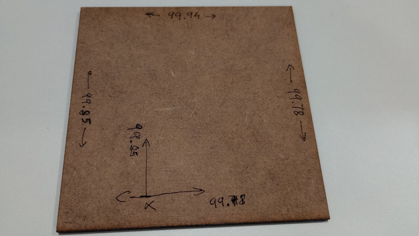
I start by cutting a square 100x100mm and I write down the x and y axis and the dimensions of each side.
In this case I am using the laser cutting control software RDWorksV8.
In the software I access the vendor tools window (File/Vendor tools/Step length) and for both X and Y I introduce the average values I measured of the sides of the square.
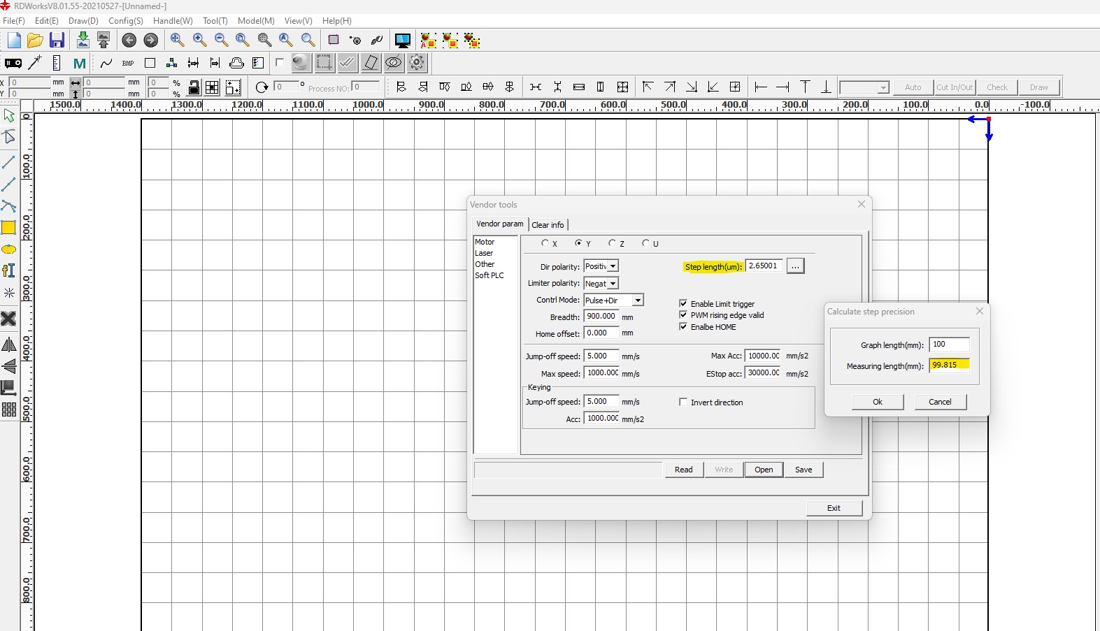
IMPORTANT: if you are not familiar with this environment, be careful not to change anything else on this window as it can affect the correct performance of the machine.
Next, I laser cut the same square with the same settings and I check the measurements.
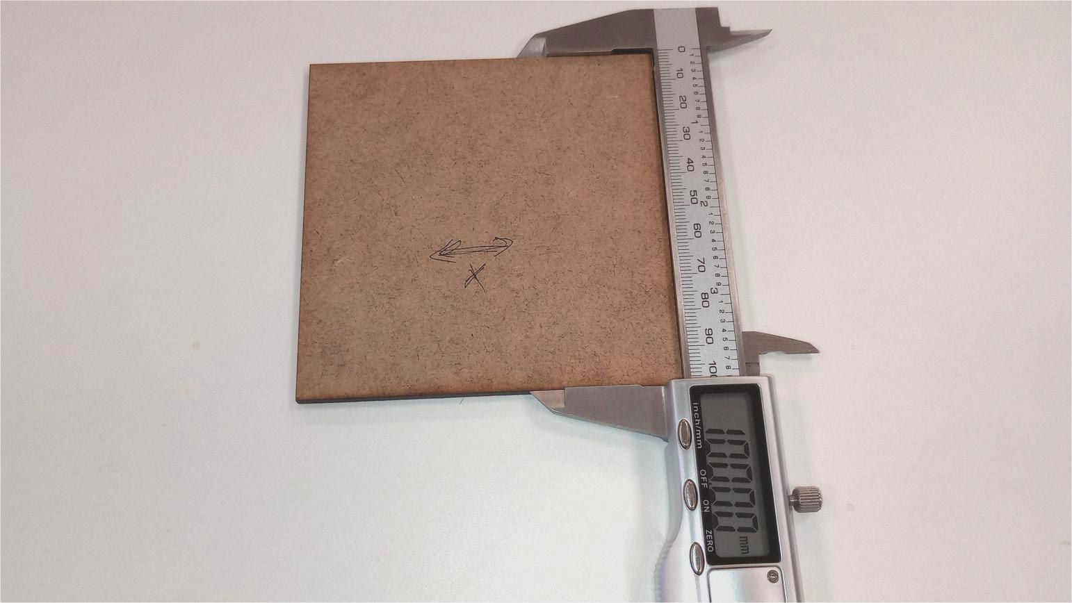
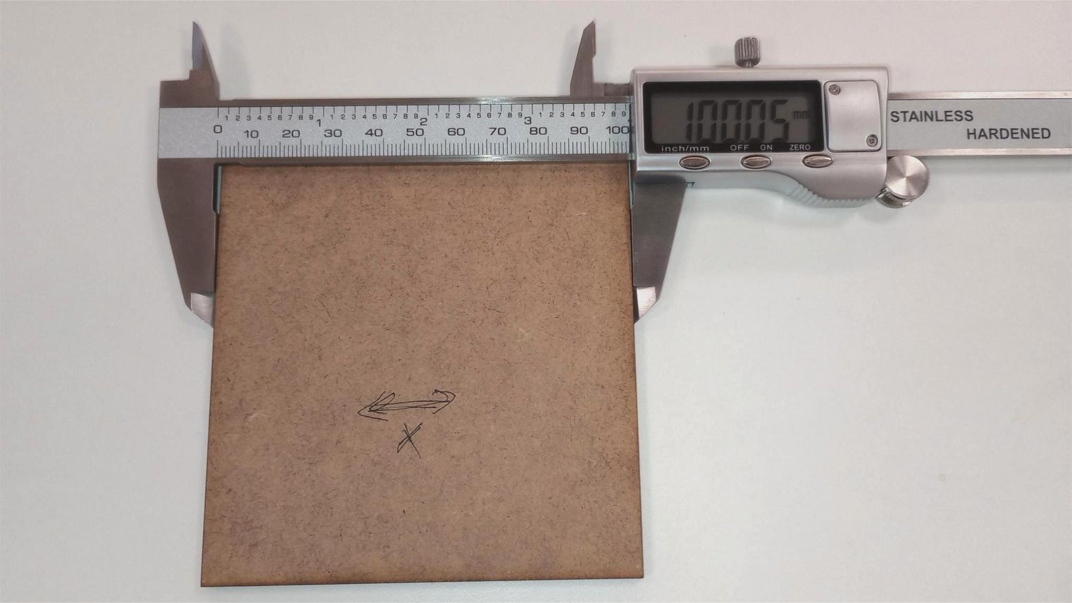
The dimensions of the cut piece now match those specified in the drawing. This means that the software has automatically accounted for the kerf allowance during the cutting process. One benefit of using this method is that you do not need to incorporate the kerf allowance into your design. However, it is important to remember to calculate and adjust this value if you are cutting different materials.
TopINDIVIDUAL ASSIGNMENT: PARAMETRIC CONSTRUCTION KIT
Calculating press-fit allowance
To calculate the appropriate press-fit dimensions for the construction kit, I created a parametric press-fit tester in Fusion with slot widths that increment by 0.5mm.

As kerf allowance, I use the value of 0.18mm which I calculated previously for 3.8 mm corrugated cardboard.
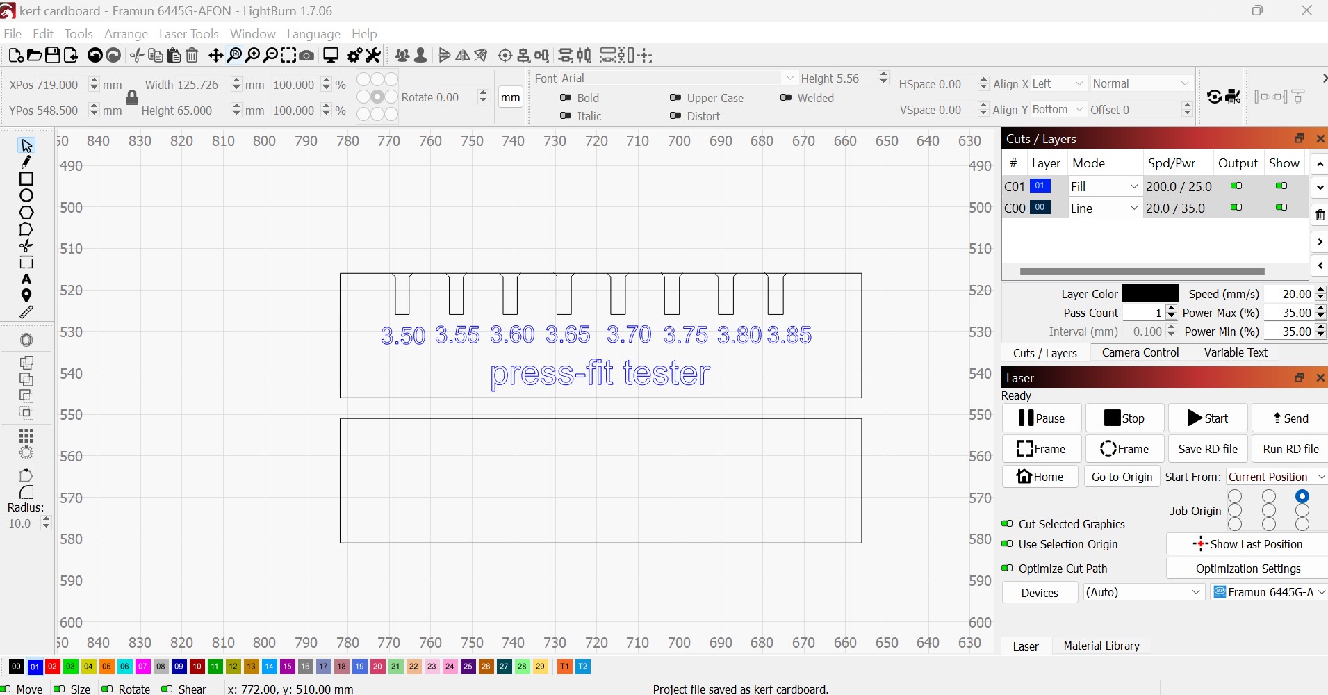
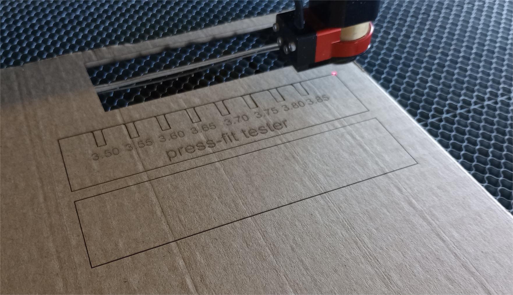
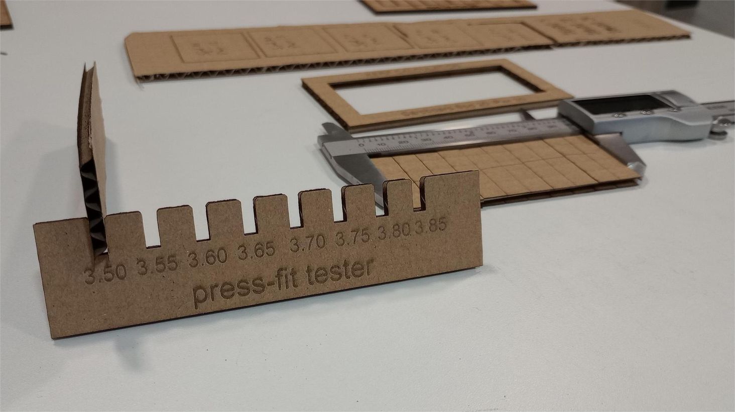
I experiment with various slot widths, and I find that the most effective ones are between 3.50 mm and 3.60 mm.
For the construction kit, I have decided to use a slot 3.55 mm wide. After accounting for the kerf allowance, I need to draw it with a measurement of 3.55-0.18=3.37 mm.
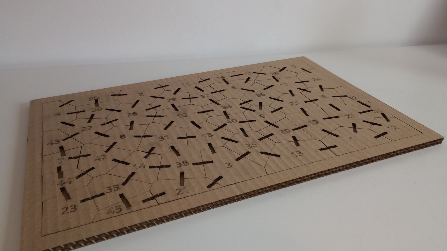
Parametric design
For the parametric design of the construction kit, I have decided to use a tessellation, specifically a Voronoi diagram. By using a Voronoi generator such as the one found at this link I can create the shapes of the pieces. What I like about this approach is that each piece will be unique, they will be nested and there will be minimal waste.
First, I considered using an online Voronoi generator to create the shapes, then importing them into a CAD software like Fusion to add slots using parametric design.
The issue with this approach is that it requires a significant amount of manual work to position each slot accurately. Ideally, I want to develop a fully parametric Voronoi generator that allows me to change the shape and size of the cells automatically, generating the slots without manual intervention.
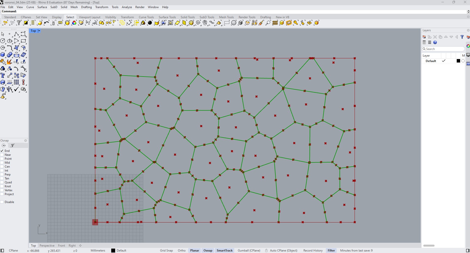
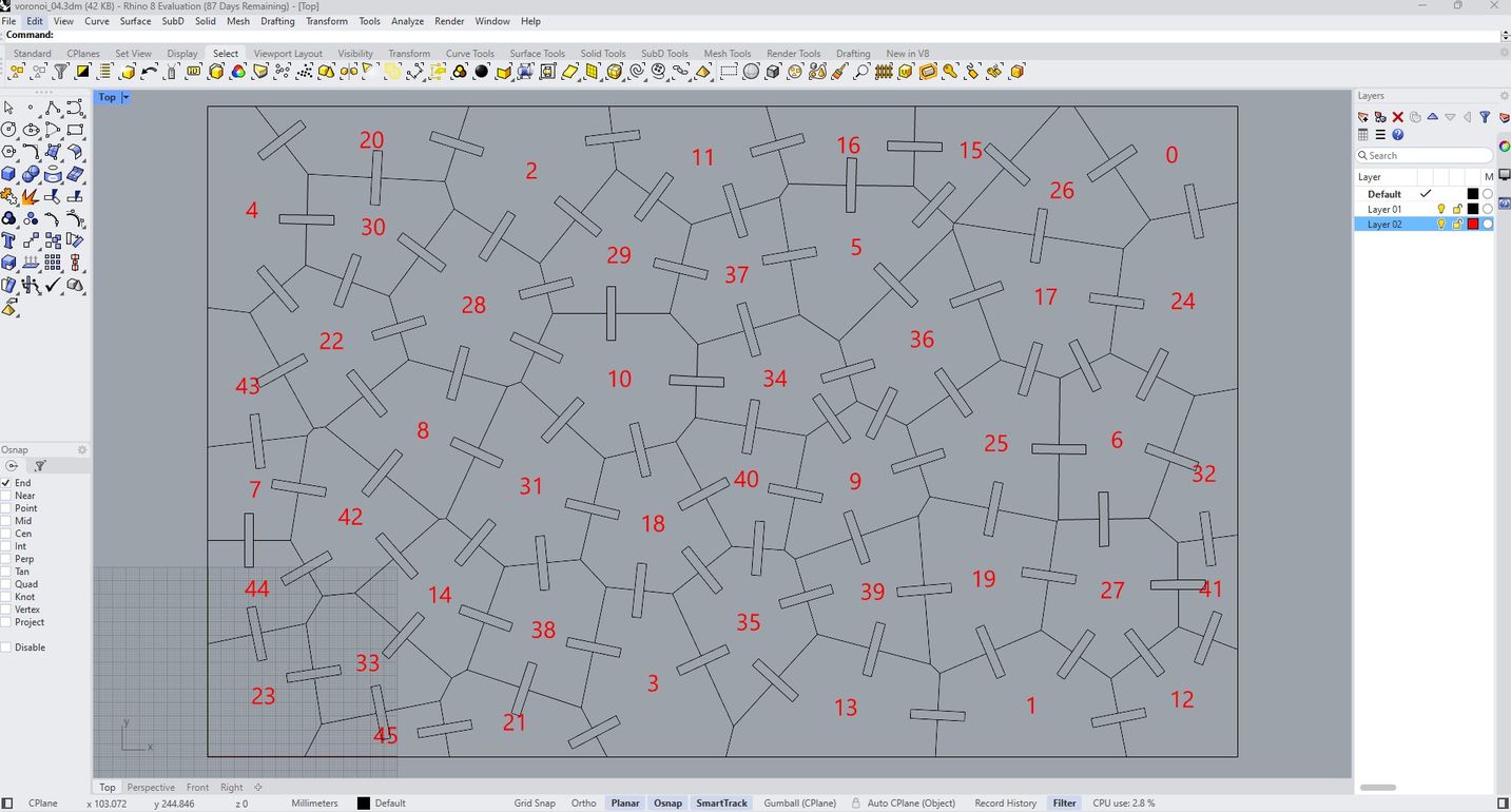
After conducting some online research, I discovered that Rhinoceros, in combination with Grasshopper, offers a Voronoi generator that can create fully parametric designs. Although I am not experienced with this software, I luckily found a video tutorial that demonstrates how to create a Voronoi puzzle, which is a very similar concept.
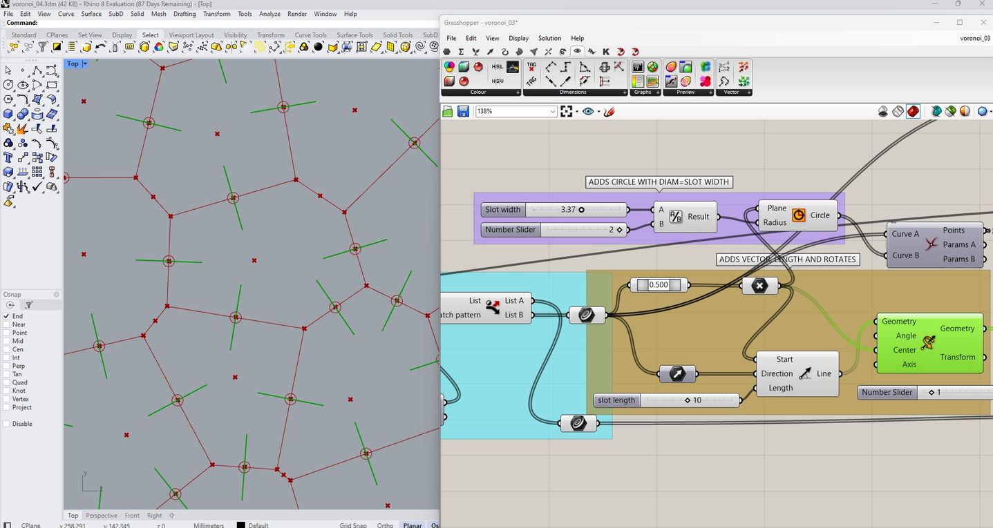
In Grasshopper, the visual programming language for Rhinoceros, I begin by adding the flowchart to define the area size and control the parameters for the Voronoi diagram.

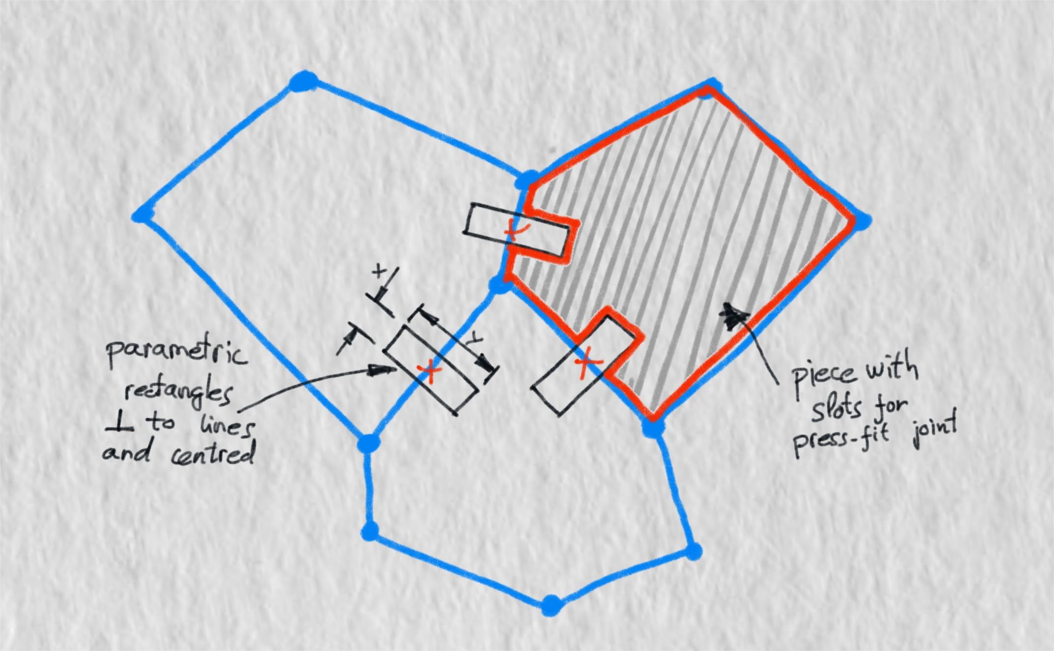
I identify the midpoint along each edge where the slots will be placed. From this midpoint, I draw a circle with a diameter equal to the width of the slots; this value can be adjusted based on the thickness of the material. Next, I draw a perpendicular line starting from the midpoint, with a length corresponding to the depth of the slots.
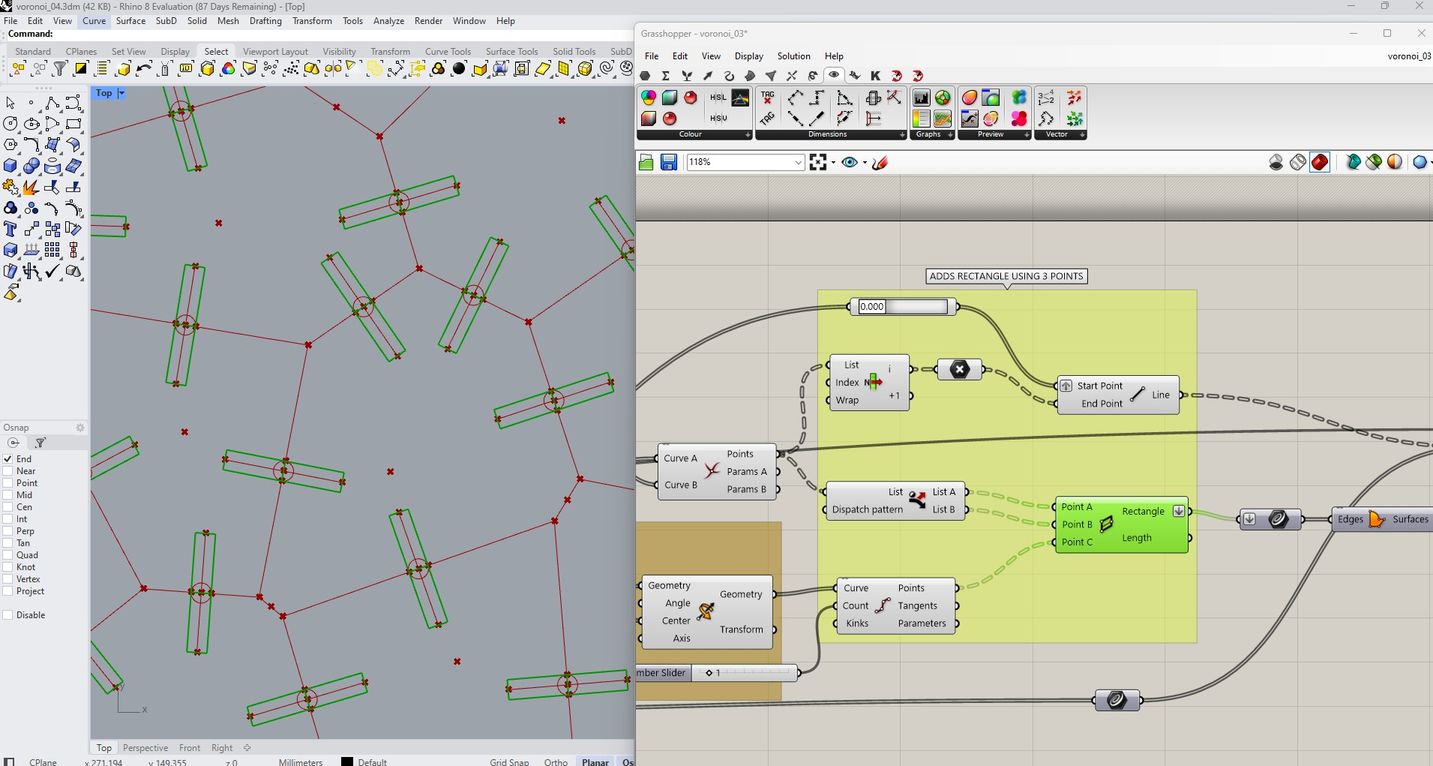
I add intersections and endpoints to generate a rectangle that represents the slot on both sides of the line.
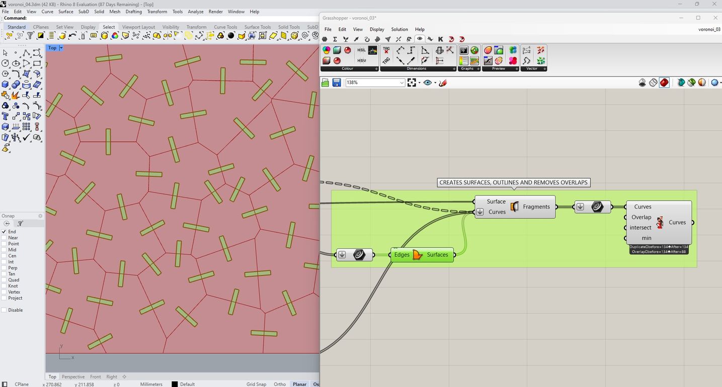
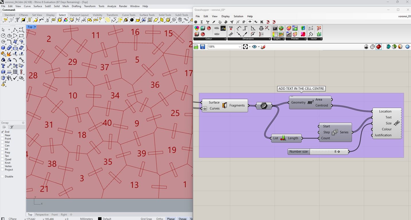
Finally, I add a number to the centroid of each cell and generate the surfaces.
The video demonstrates how geometry changes with parametric adjustments.
I attempted to add chamfers at the ends of the slots, but it proved quite challenging. Unfortunately, I was running out of time, so I decided to move on.
Now, I can specify the slot width and length required for the construction kit to work as a press-fit. After conducting the previous press-fit test, I decided to use the following values:
- Slot width: 3.37 mm
- Slot length: 10 mm
I also defined the overall dimensions as 380 x 240 mm. I experimented with the size and arrangement of the cells until I am satisfied with the results.
To convert the parametric geometry into permanent geometry in Rhino, I use the Bake command. This enables me to export the design and prepare it for laser cutting. I do this with the lines and numbers separately so I can send them to different layers.
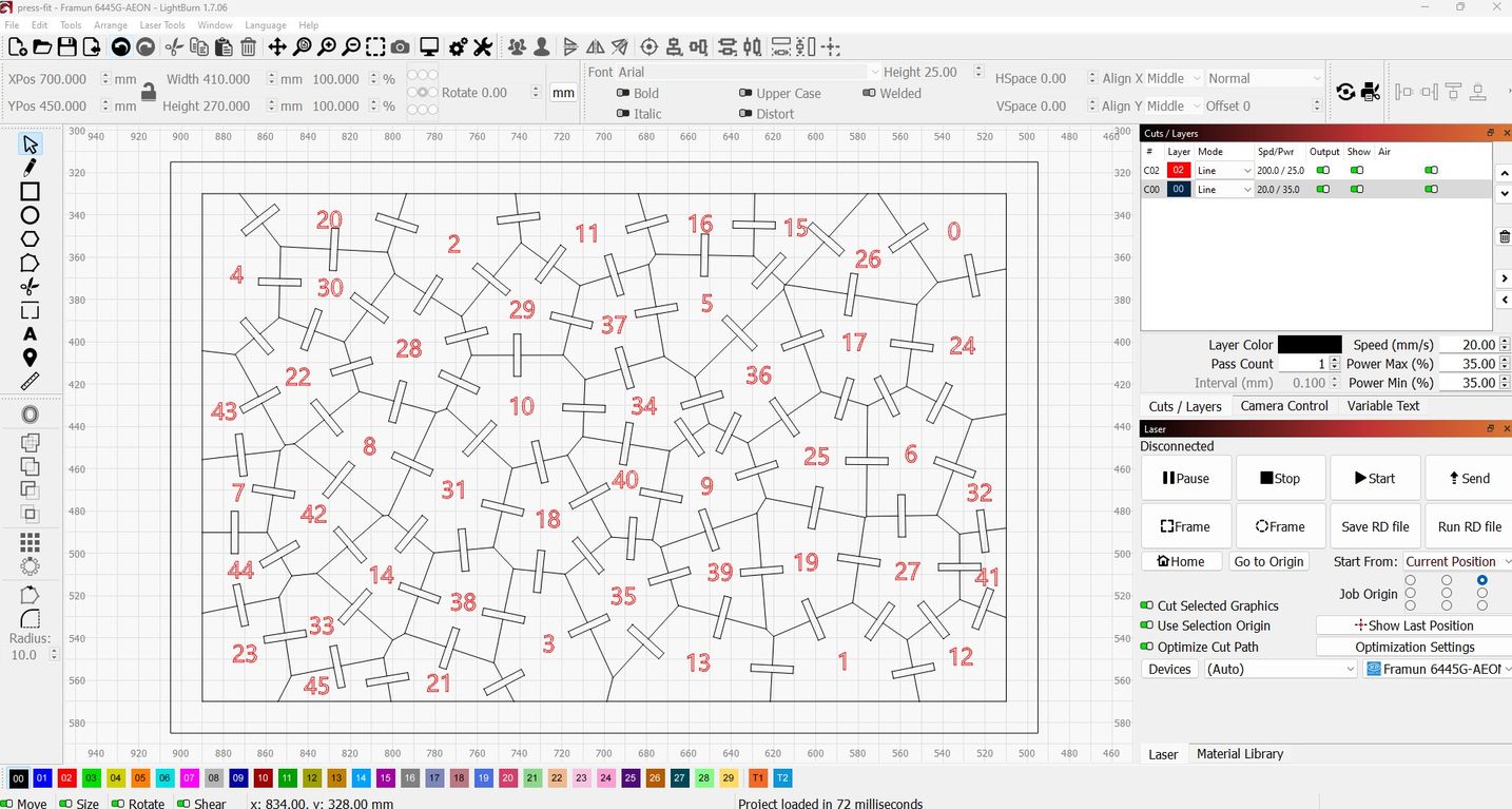
To cut the design I use the following settings:
- Cut: Speed 20 / Power 35
- Trace numbers: Speed 200 / Power 25
In LightBurn I check that there are no duplicate lines.
I also decided to add a frame around the design as I am thinking about creating a tray to keep the pieces organized.
I setup the piece of cadboard and I focus the laser.
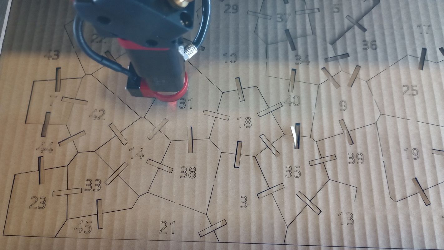
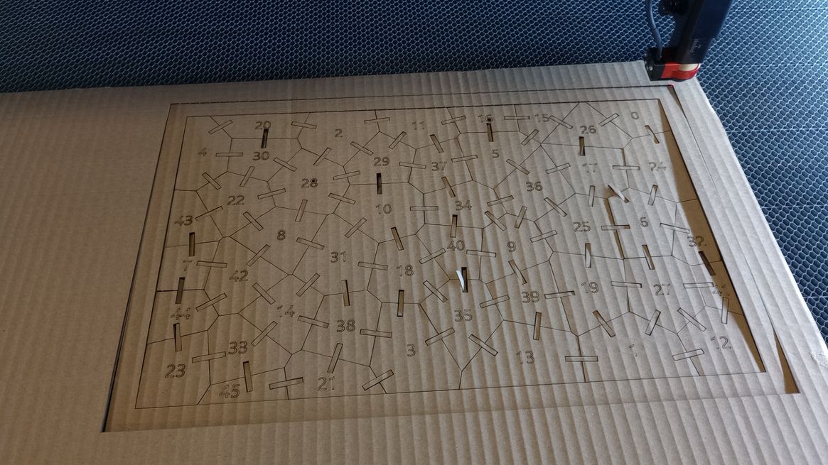
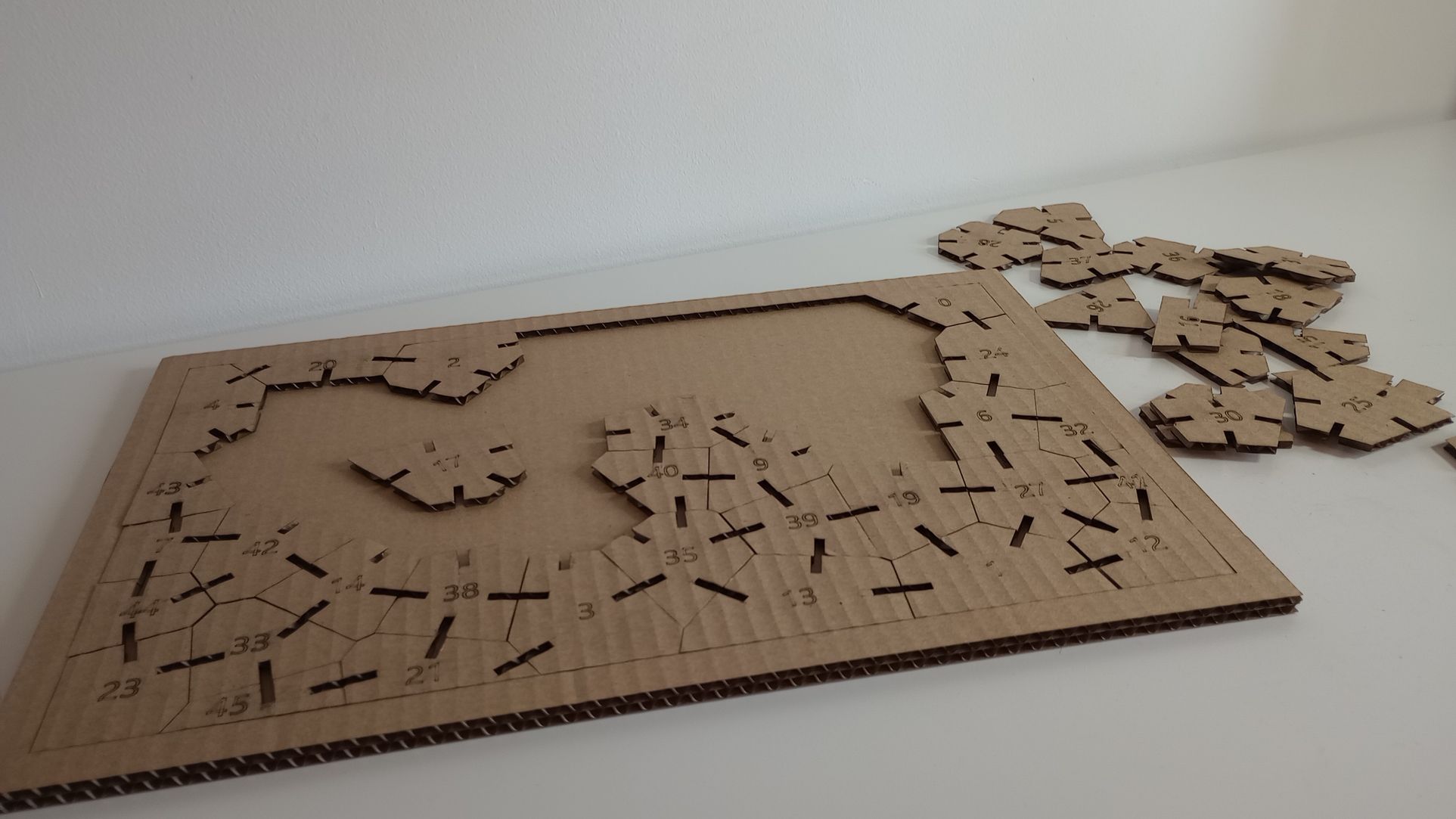
After a few minutes, all the pieces were nicely cut. The cutting settings were ideal for the material and thickness used. With the frame and an additional rectangular piece of cardboard, I created a tray to keep the cut pieces organized.
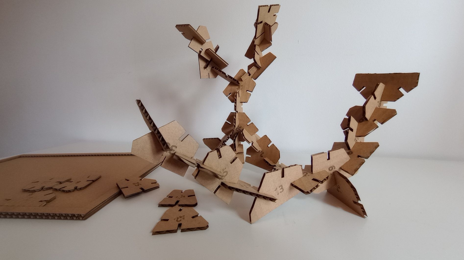
This way, the kit can function both as a puzzle and a press-fit construction kit. Since all the pieces are unique, the resulting shapes can be quite abstract. Although the cardboard quality isn’t great, the press-fit works very well. I believe it would perform even better with chamfers added to the corners of the slots, so I see this as a necessary future improvement for the project.
 Top
Top
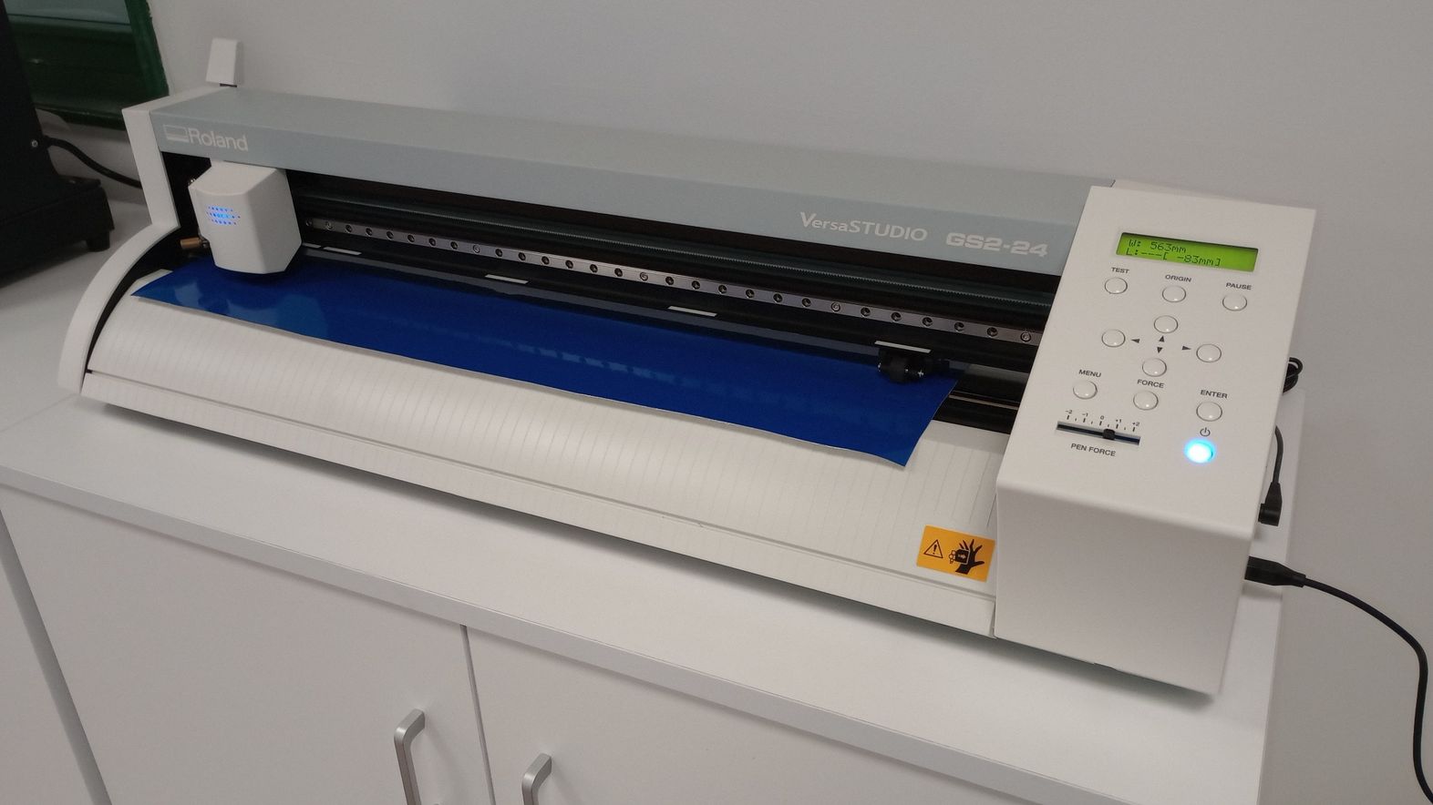
VINYL CUTTING
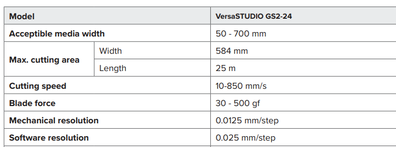
Model: Roland VersaSTUDIO GS2-24
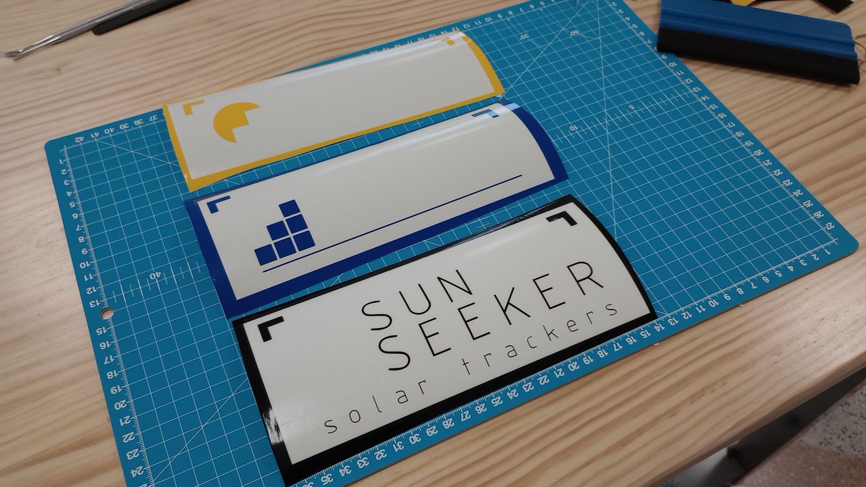
For my vinyl cutting task, I’ve decided to use the logo I designed in Inkscape during week 2. The logo has three colors, so I separated each color and added datum marks to ensure proper alignment for each part.
In Inkscape, I installed a plugin that allows me to send the design directly to CutStudio, the control software for the Roland cutter.
Since I am using surface vinyl, there is no need to mirror the images as I would when using heat transfer vinyl for textiles.
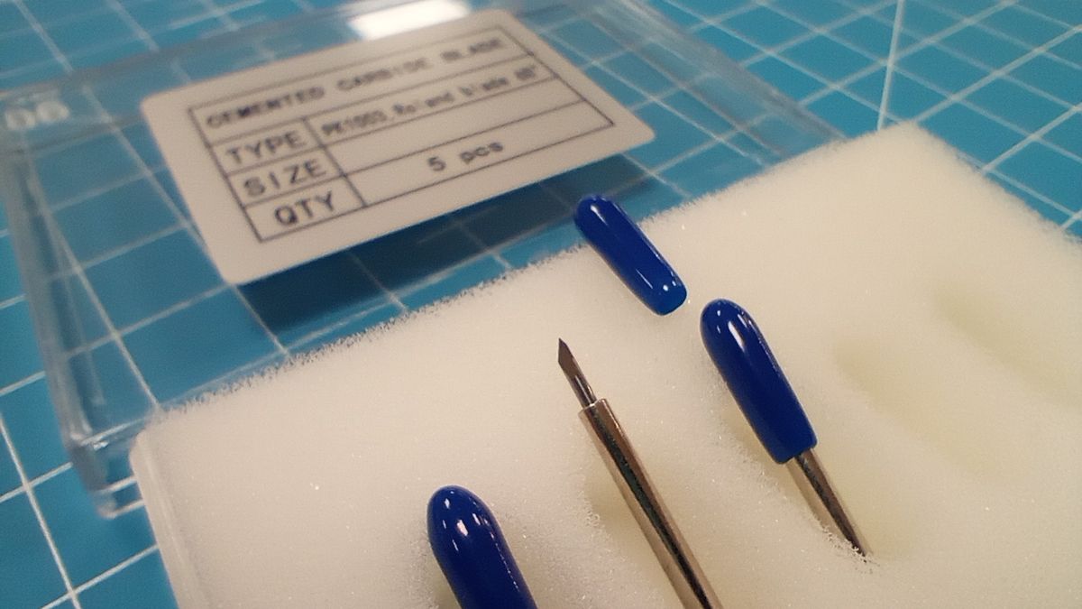
I load one of the rolls and perform a test cut to adjust the cutting force of the blade. The blade I am using has a 60-degree cutting angle, which is recommended for thicker materials.
These were the settings used:
- Cutting force: 65 gf
- Cutting speed: 20 cm/s
I then cut the three parts in their corresponding colors.
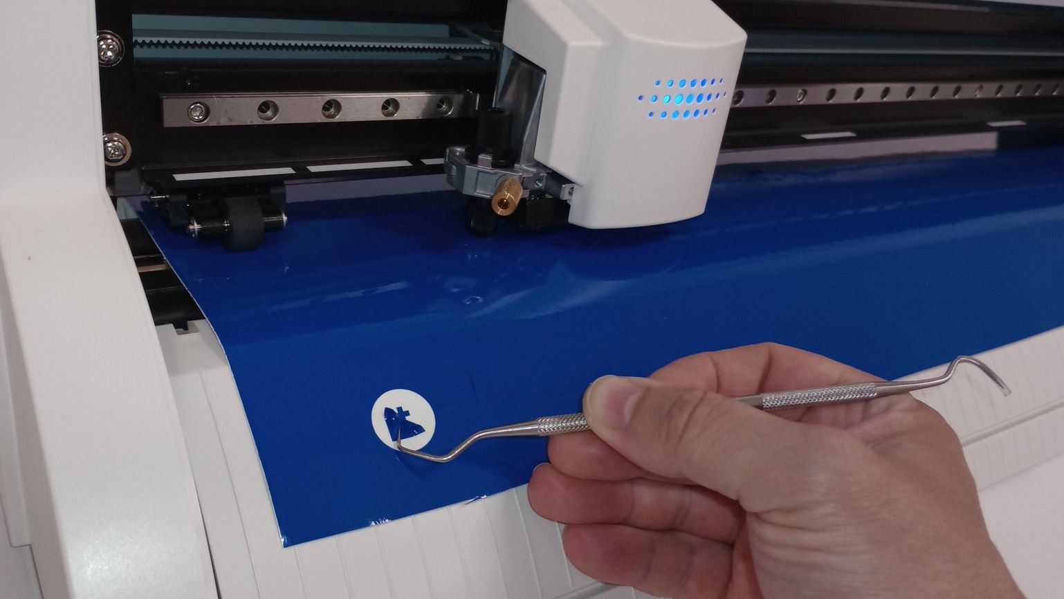
Next, I gather all the necessary tools: a craft knife, squeegee, weeding tool, fine-point tweezers, cutting board, ruler, and a steady hand!.
Using the weeding tool, I carefully remove the excess material, leaving only the design on the backing sheet.
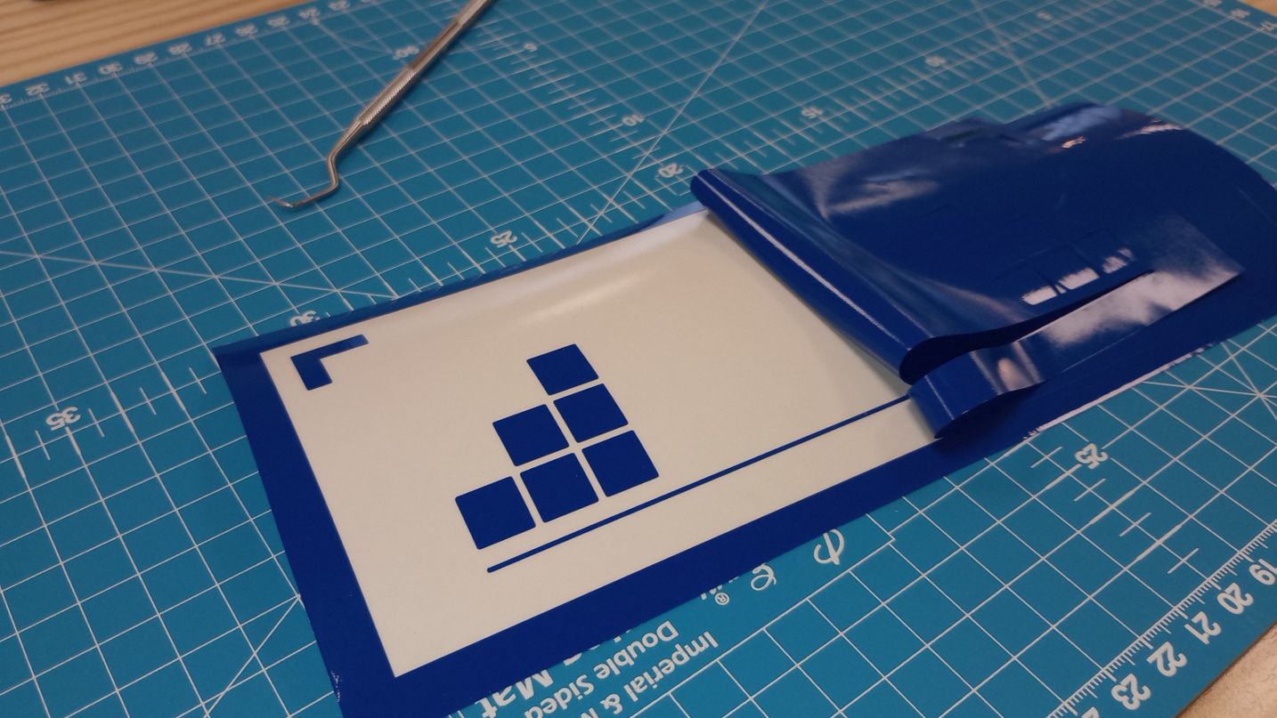
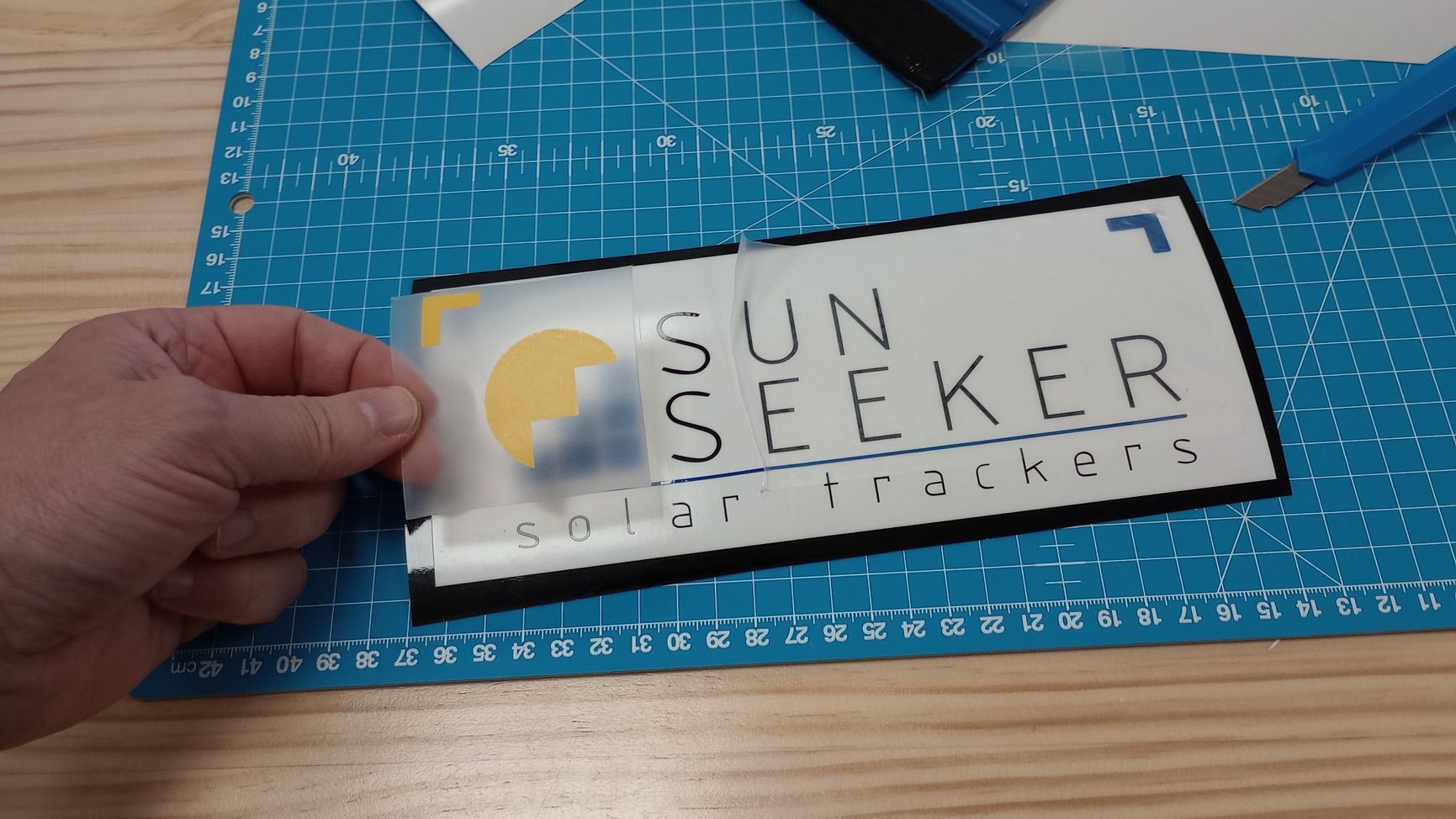
I apply transfer tape to the blue and yellow parts and then align them with the piece that has the black lettering. Once all the parts are combined onto one backing sheet, I apply transfer tape, remove the backing sheet, and stick the design to a piece of white vinyl.
To prevent bubbles and ensure good adhesion of the vinyl, I use the squeegee.
And... squeegee, squeegee, squeegee!
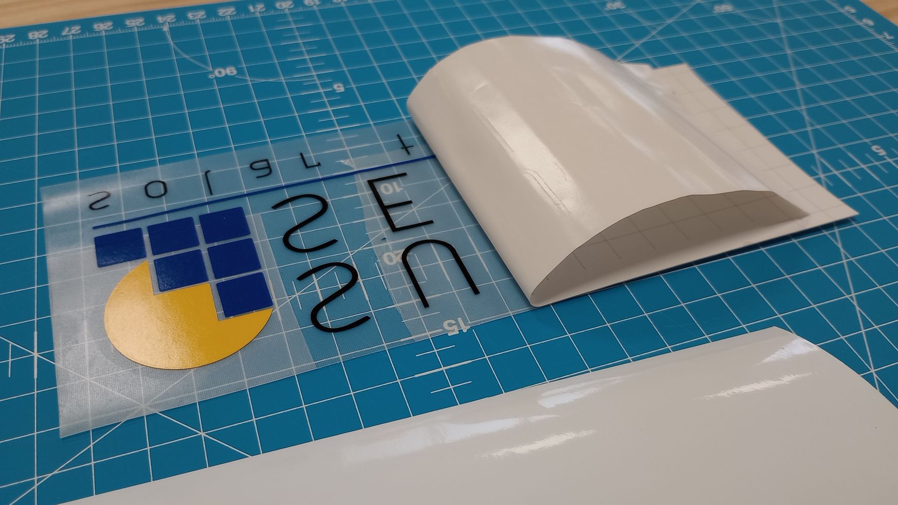
Finally, I remove the transfer tape, and voilà! The vinyl is ready to be applied to my final project (which hopefully will be complete in 16 weeks!).
TopUSEFUL LINKS AND RESOURCES
- Voronoi Puzzle Rhino Grasshopper video tutorial
- What Is Laser Cutting Kerf? Post in ACCURL website explaining laser cutting Kerf
- Aeon Laser Nova Elite14 Link to laser model in our workshop
- How to Find the Kerf of a Laser in LightBurn
- What do the laser parameters mean?
- Inkscape plugin Inkscape plugin that converts SVG files to an EPS format that Roland's CutStudio software can read.
- Laser Cut Material Testing Board Template Free Vector
FILES
Kerf calculation tool (.dxf): Download link
Press-fit tester (Fusion.f3d): Download link
Construction kit (Grasshoper.gh): Download link
Material Test Card for 3mm MDF (RDworksV8.rld): Download link
2D Inkscape logo design (.svg): Download link
Top