Week 09. Input Devices

WEEKLY PLAN
Group assignment:
- Probe an input device(s)'s analog levels and digital signals
Individual assignment:
- Measure something: add a sensor to a microcontroller board that you have designed and read it
GROUP ASSIGNMENT: PROBE INPUT DEVICE
This is the link to the Fab Lab León Group Assignments page. Since I am completing the group assignment on my own I left the documentation on this page.
PROBE ANALOGUE INPUT
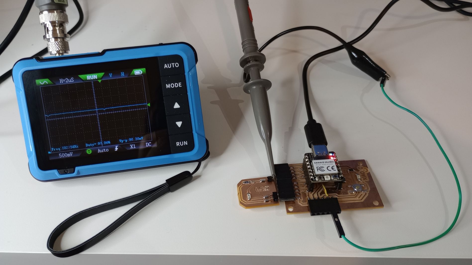
Here I am using the oscilloscope to measure the analogue signal on the pin of the light sensor module I fabricated for the individual assignment.
I connected the probe to the signal pin and the crocodile clip to a GND pin on the development board.
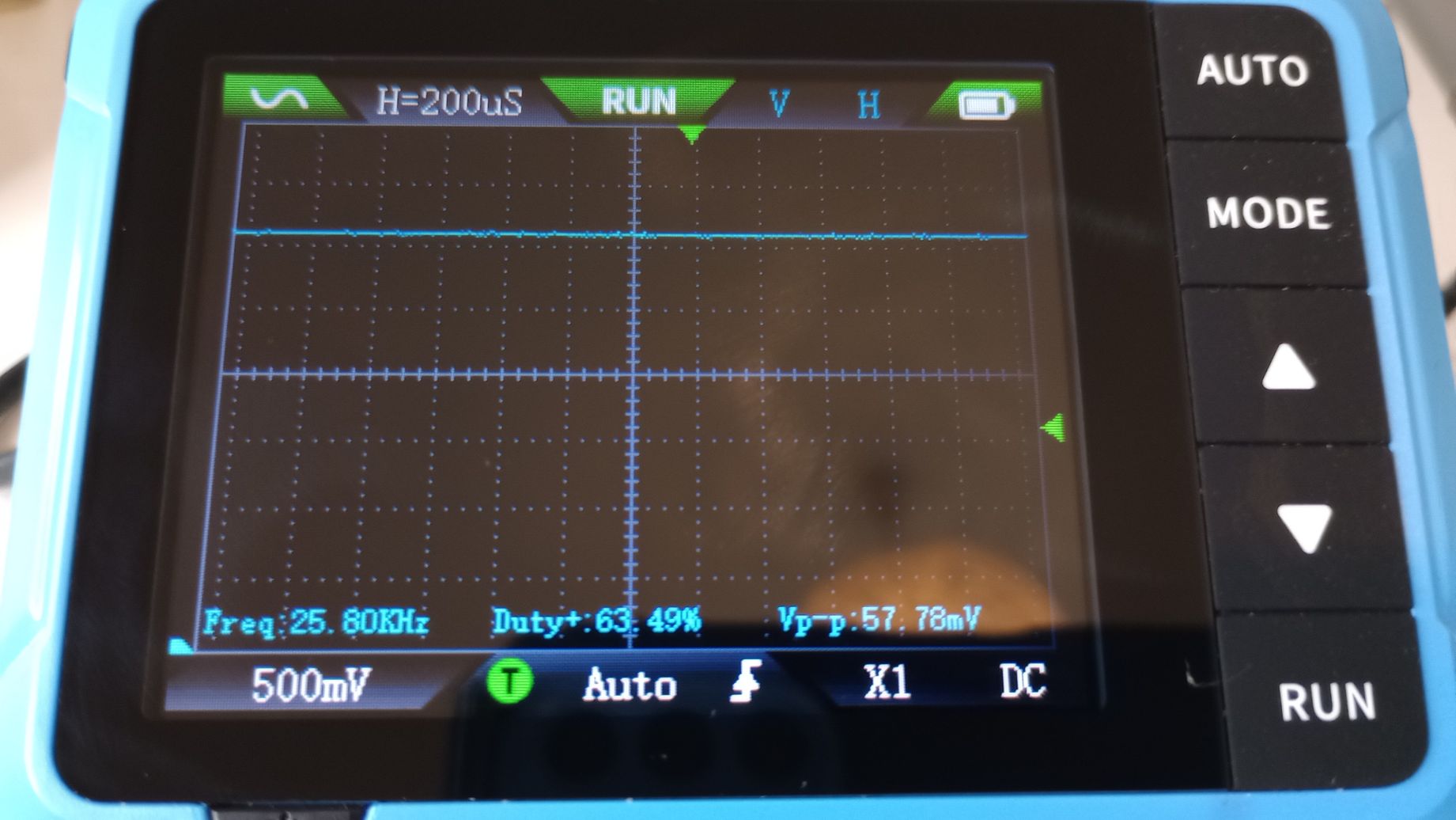
When less light hits the phototransistor the voltage on the signal pin increases from 40mV to 50mV.
The horizontal axis measures time with a 200μs scale and the vertical measures voltage with a 500mV scale.
PROBE DIGITAL INPUT
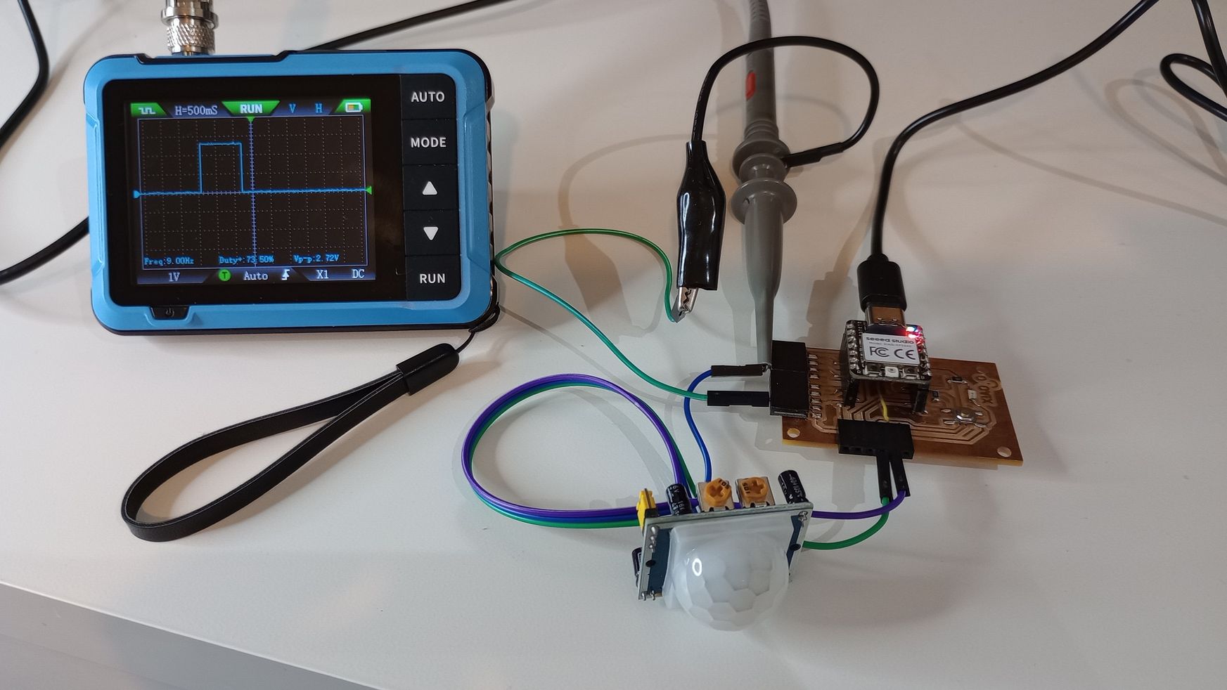
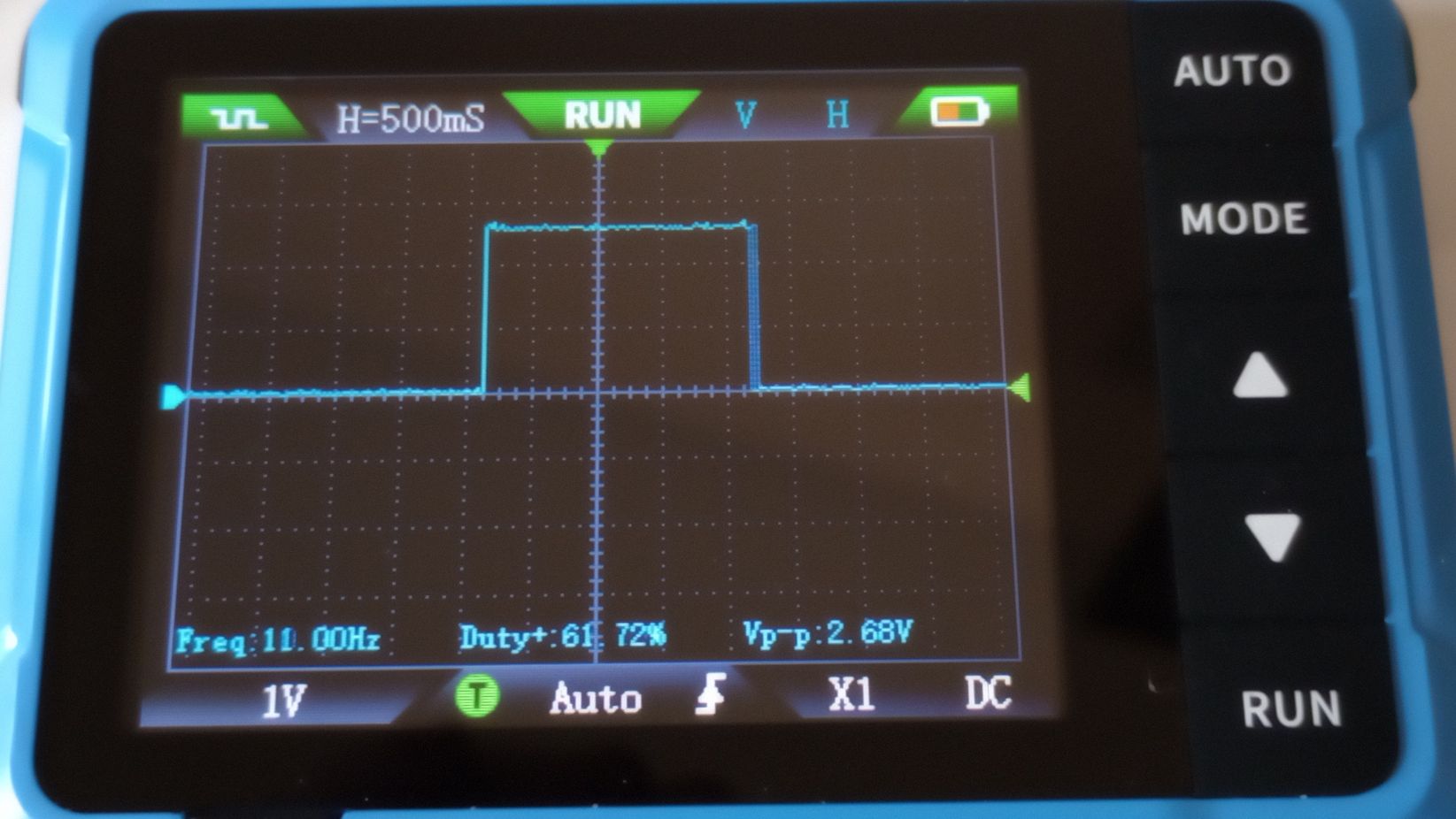
Here I am using the oscilloscope to measure the digital signal of a PIR movement sensor.
I connected the probe to the signal pin and the crocodile clip to a GND pin on the development board.
The horizontal axis measures time with a 500ms scale and the vertical measures voltage with a 1V scale. When the sensor is triggered it sends a HIGH signal to the board, and the oscilloscope reads a Vp-p= 2.68v.
Top
INDIVIDUAL ASSIGNMENT: MEASURE INPUT DEVICES
DESIGN AND FABRICATION OF SENSING MODULE
My final project is a dual-axis solar tracker so the focus for this assignment is going to be light sensing .
During week 6 and 8 I have designed and fabricated a development board with a XIAO RP2040 which I am going to use this week.
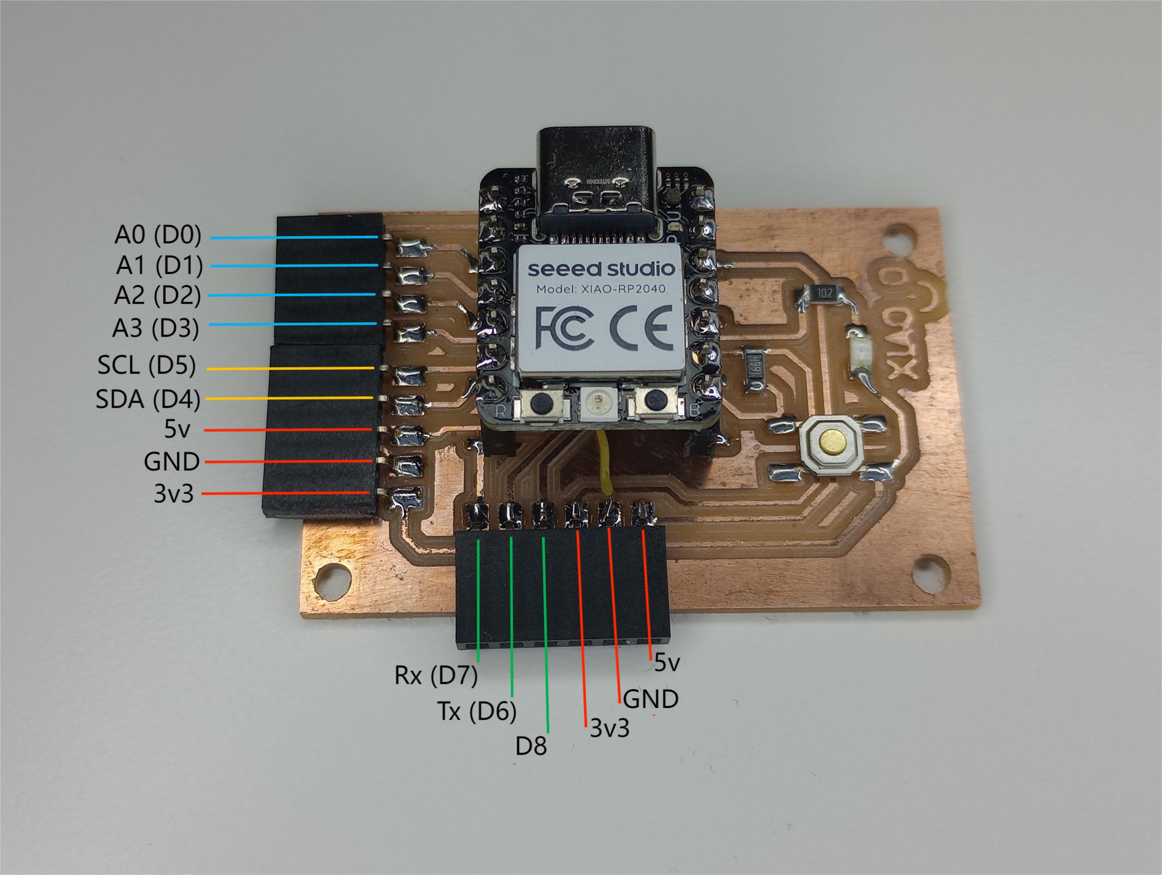
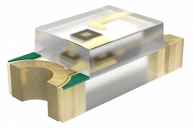
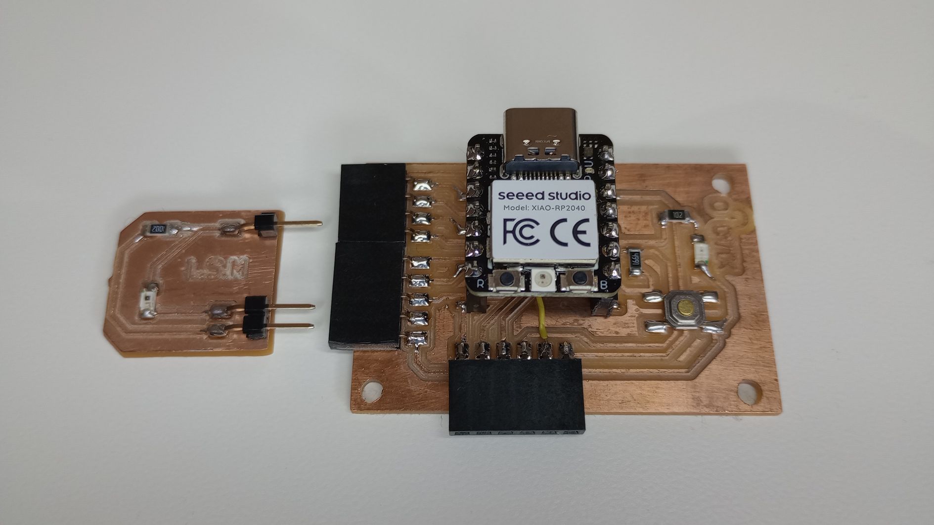
I am going to start by designing and fabricating a light sensing module (LSM) with a phototransitor PT15-21C.
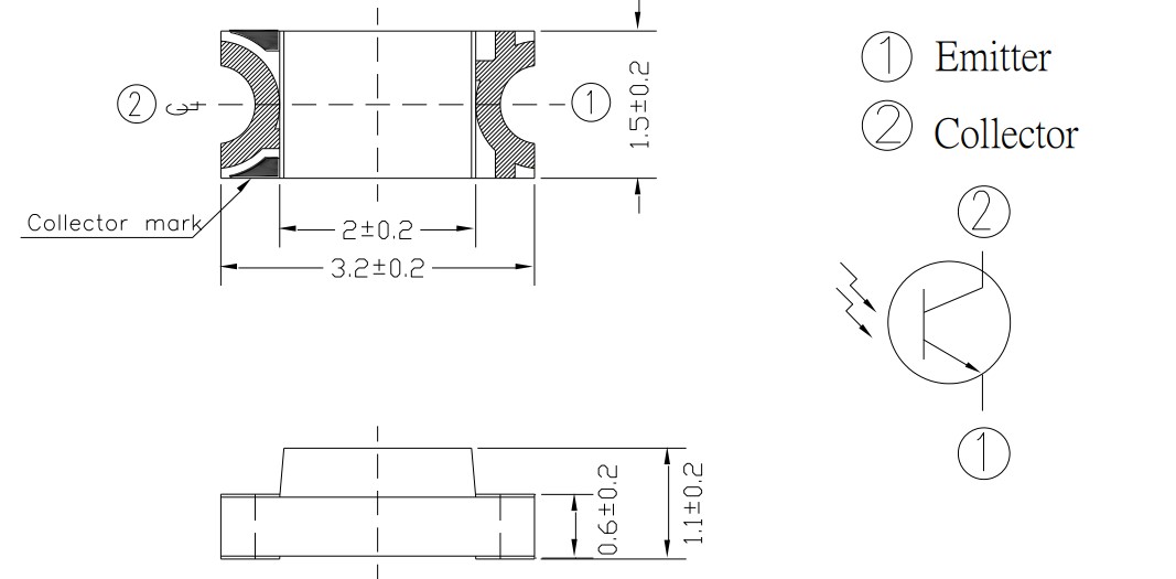
A phototransistor functions similarly to a regular transistor but is sensitive to light. It has three main parts: the emitter, base, and collector.
- Emitter: is the terminal through which current exits the phototransistor.
- Base: When light strikes the base, it generates charge carriers (electrons ) in the semiconductor material, which controls the flow of current. The base does not need an external voltage; instead, light acts as the trigger to initiate current flow.
- Collector: The collector is the terminal through which the current enters. As light strikes the base, it allows current to flow from the collector to the emitter, depending on the intensity of the light.
The phototransistor amplifies the current flowing from the collector to the emitter, based on how much light is detected at the base, converting light into an electrical signal.
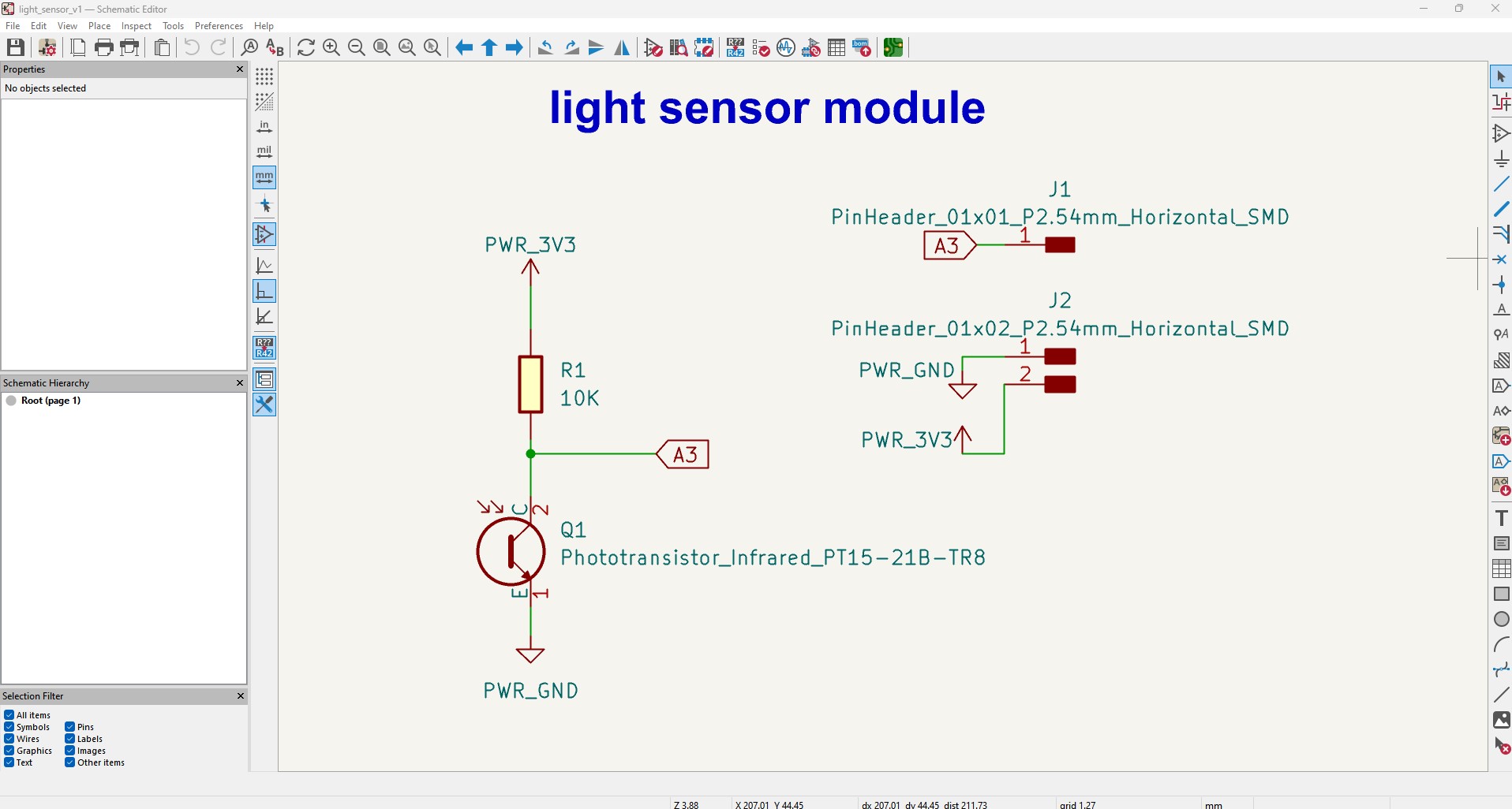
Based o the schematic created on Kicad9.0 I generated and routed the tracks as shown below. I made sure the pins would have the correct separation to connect on the analogue, 3v3 and gnd pins of the development board.


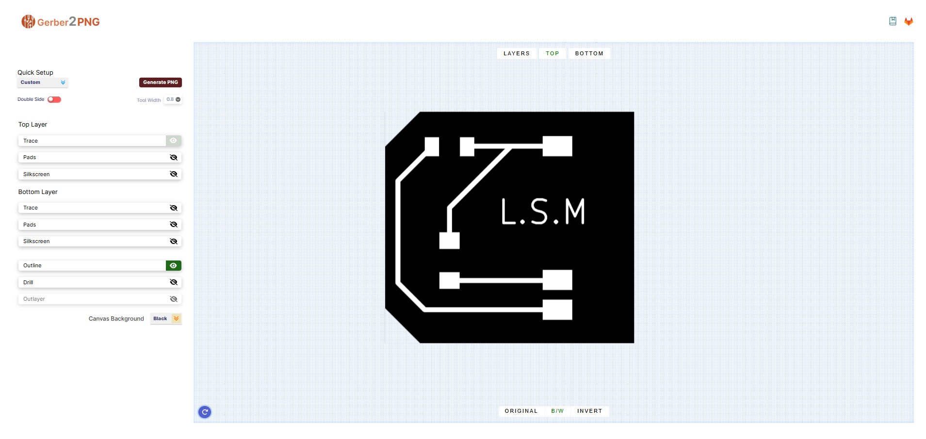
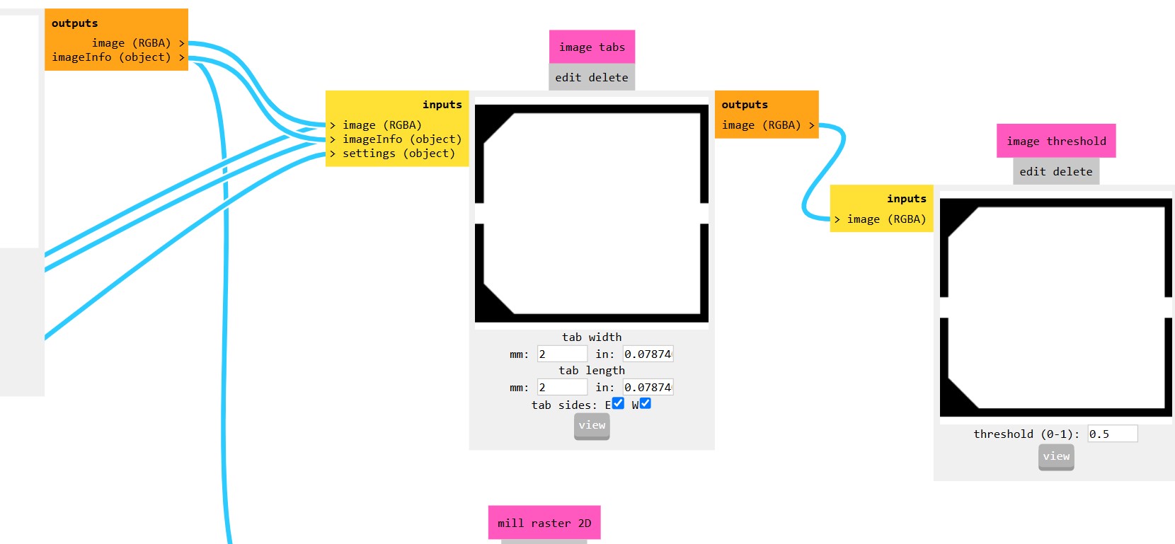
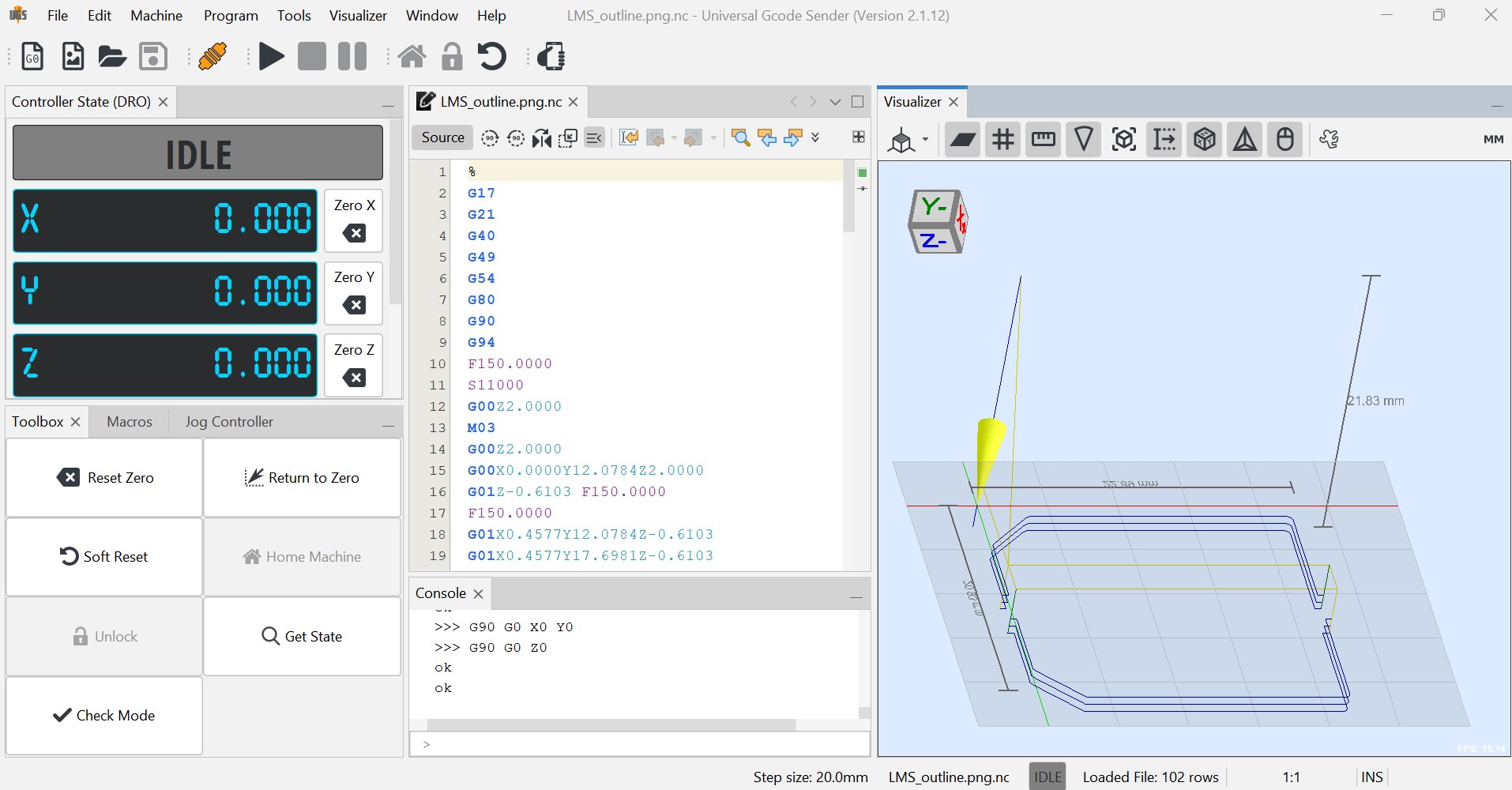
From Kicad I export the Gerber files and I import them into Gerber2PNG to generate the tracks and outline png files
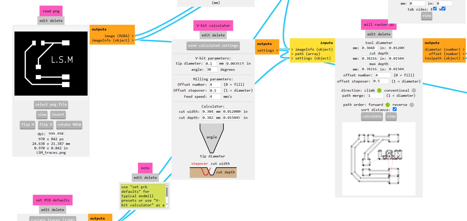
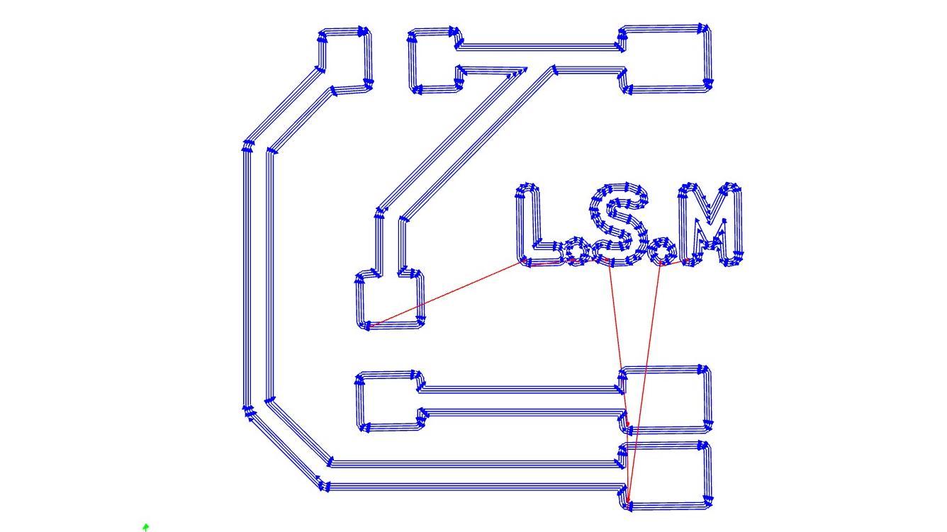
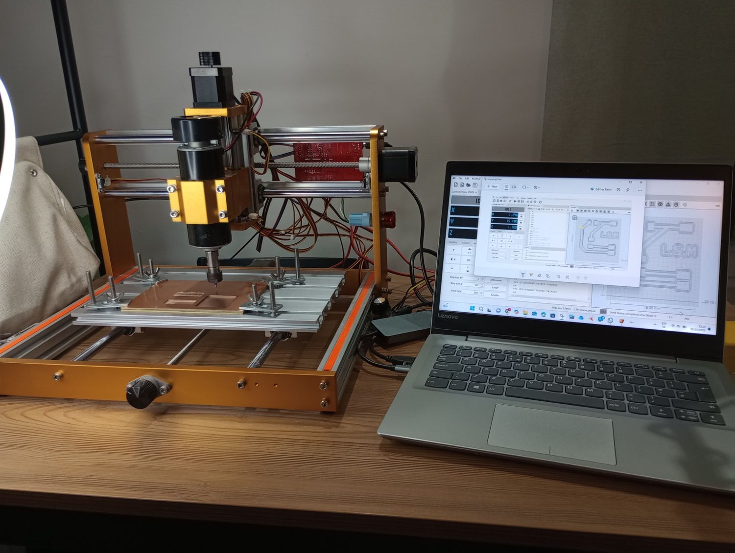
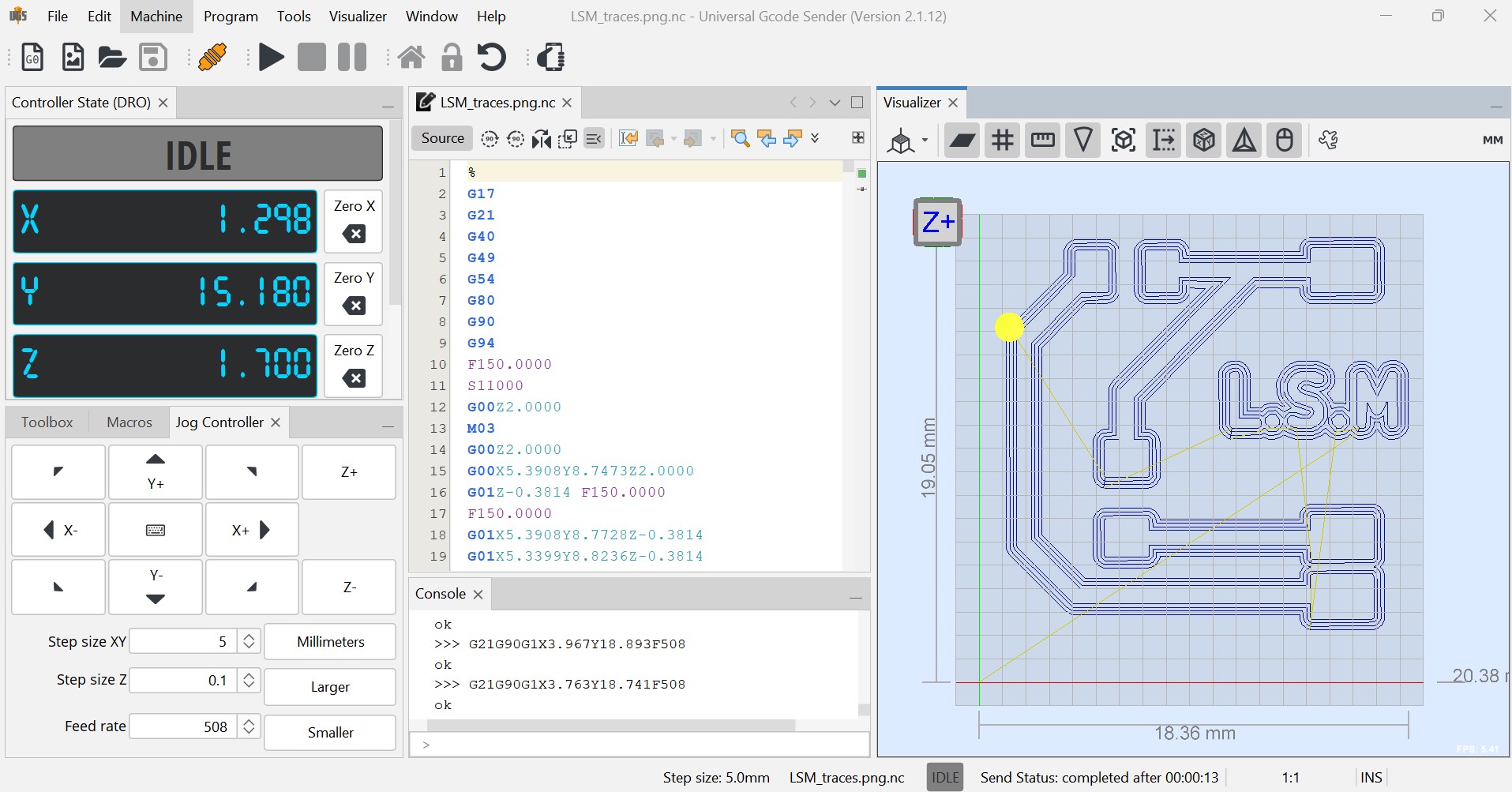
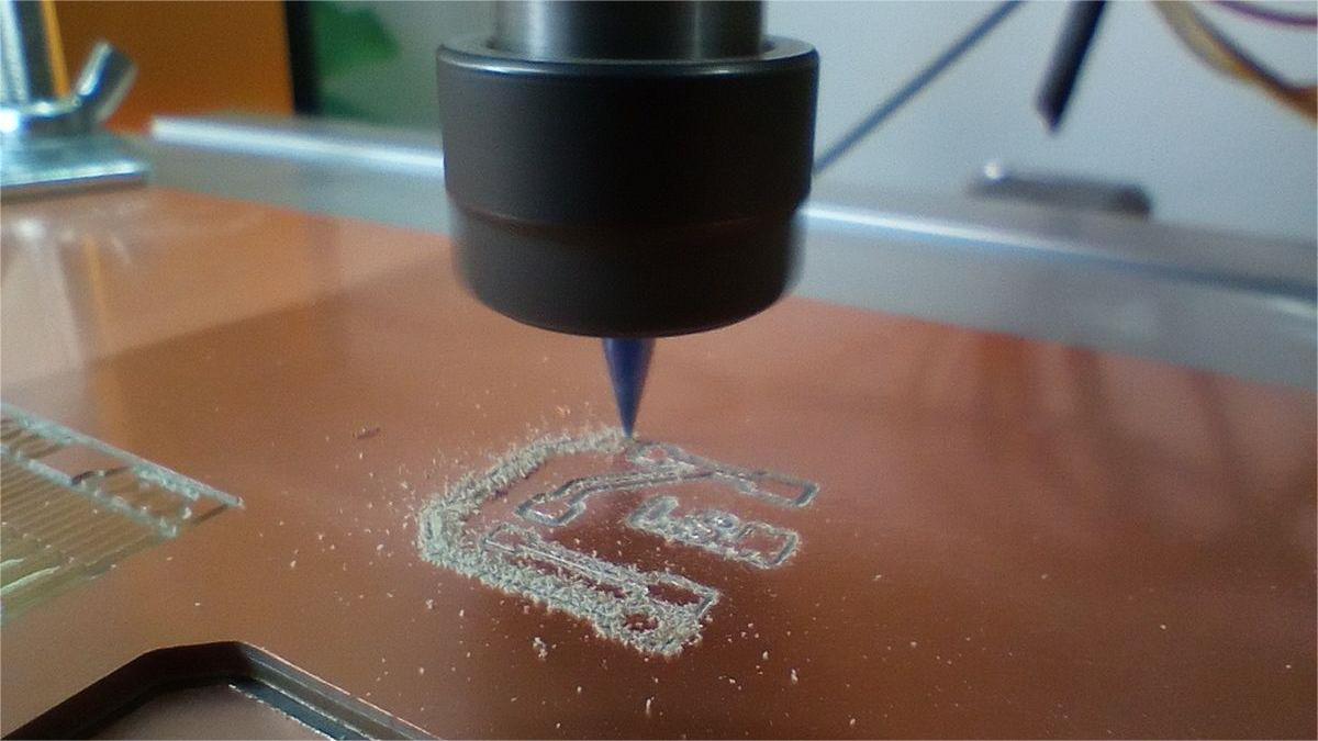
To fabricate the module I am using the CNC milling machine Lunyee 3018 Pro Max. I load the png files on Mods.org and select the V-bit calculator to machine the traces.
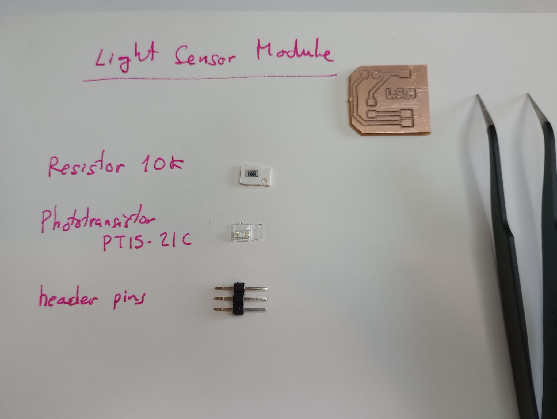
These are the components required to complete the module:
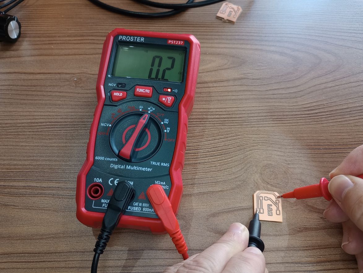
Before populating the board I use an multimeter to check the continuity of the board.
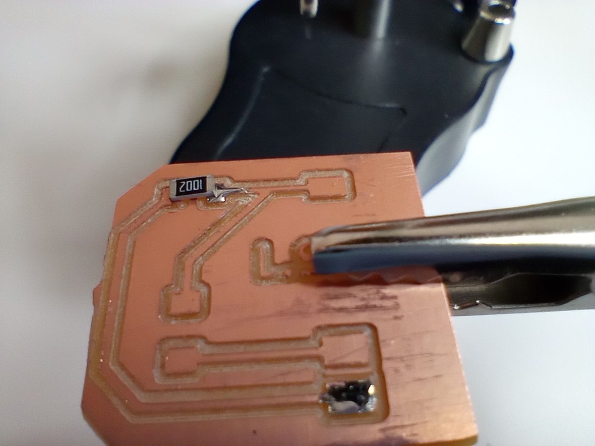
I start by placing and soldering the resistor, then the phototransistor and finally the pins.

I check that the light sensor module fits in the development board. Now is time to program the board and get some readings from the module.
READING FROM THE SENSOR MODULE
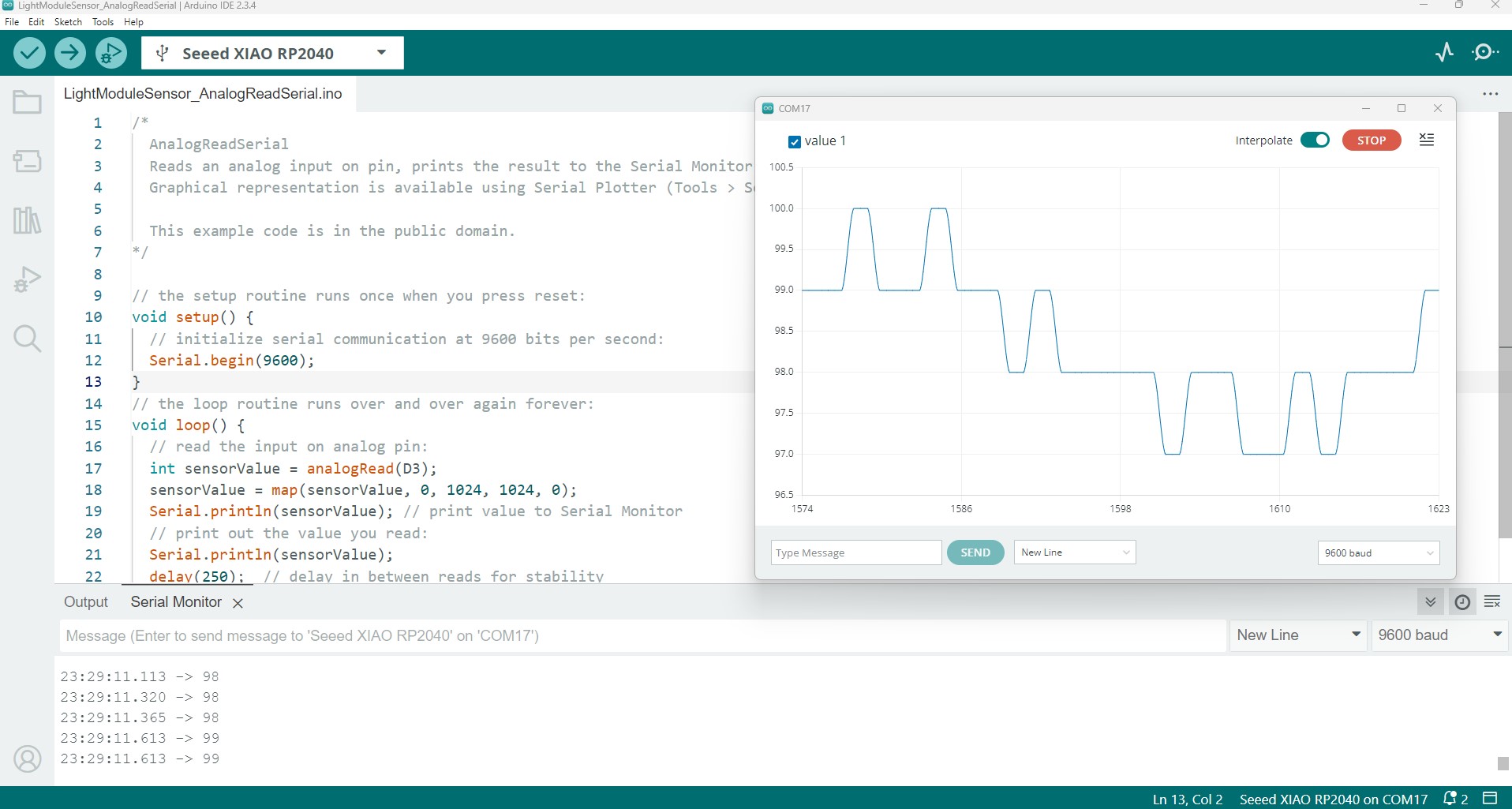
In Arduino IDE I modified the AnalogeReadSerial.ino example to read the pin D3 of the Xiao RP2040.
LIGHT SENSOR MODULE FOR FINAL PROJECT
As part of the individual assignment I decided to design and fabricate the light sensor for my final project, a dual-axis solar tracker. This sensor has 4 phototransistors that are arranged in quadrants and are going to be housed in a casing. The casing will produce shadow on the sensors when not directly aligned with the sun’s direction.


FILES
Light Sensing Module KiCad - Schematic and PCB : light_sense_module_kicad9.zip
Light Sensing Module - traces and outline .png : Light_Sensor_Module_png.zip
Light Sensing Matrix KiCad - Schematic and PCB : light_sense_matrix_kicad9.zip
Light Sensing Matrix - traces, drills and outline .png : ligth_sense_matrix_png_files.zip
Top