Week 16. System Integration
Design and document the system integration for your final project.
INDIVIDUAL ASSIGNMENT: SYSTEM INTEGRATION
System overview & requirements
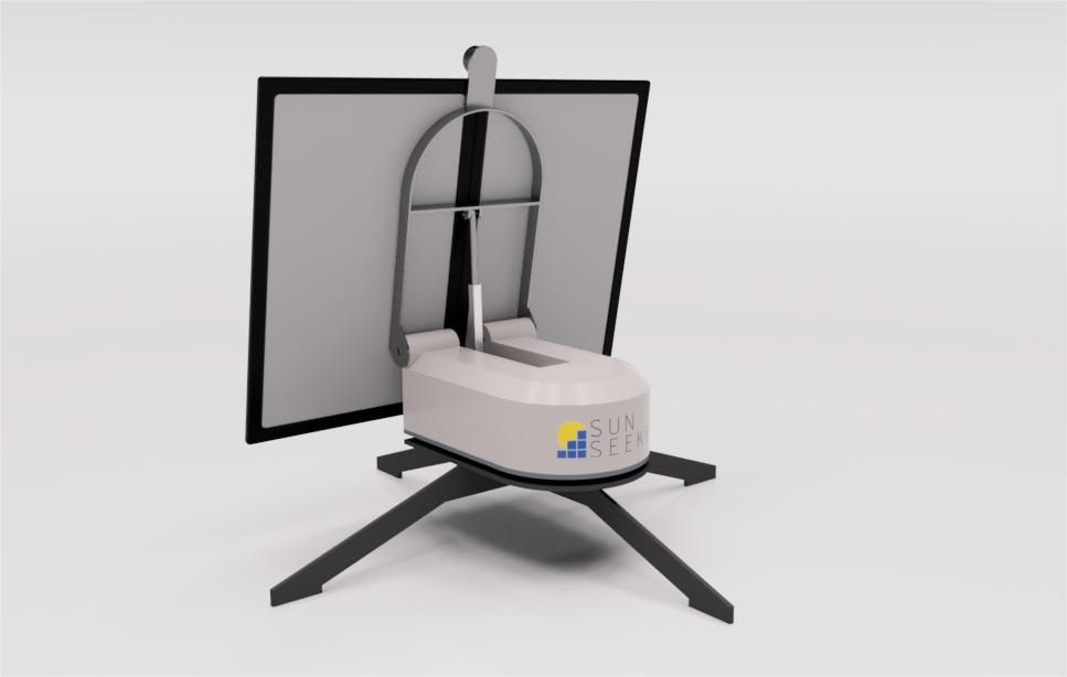
The project is an automatic dual-axis sun-tracking device for a small photovoltaic (PV) panel. The product operates autonomously and is self-powered by a 12 V rechargeable battery charged from the PV panels. The battery supplies the tracking system and a 12 V DC outlet
Some key features I wanted to integrate into the product are:
- Dual-axis tracking:independently control azimuth (rotation) and elevation (tilt).
- Self-powered:integrated 12 V rechargeable battery
- BLE connectivity: manual setup/control via a mobile app and the ability to start/stop tracking.
- Automation:night mode, periodic sun-tracking cycles, and a defined home position.
- Safety and UX: on/off switch, stop/disable tracking, soft limits and homing.
- Serviceability:parts and wiring accessible for maintenance.
- Portability: consider weight, size, and detachable parts for transport.
- Outdoor readiness: weather resistance and operating temperature range.
Design approach
The design progressed from concept sketches to a preliminary CAD assembly, and then to a fully detailed CAD model including all components. The model verifies clearances, assembly sequence, and fastener access. Each custom part was designed for the intended manufacturing process and to integrate with off-the-shelf components.
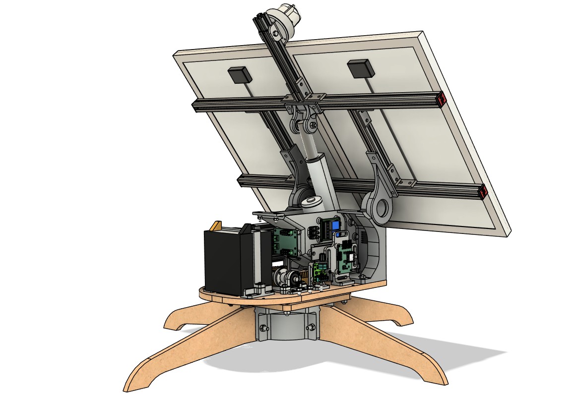
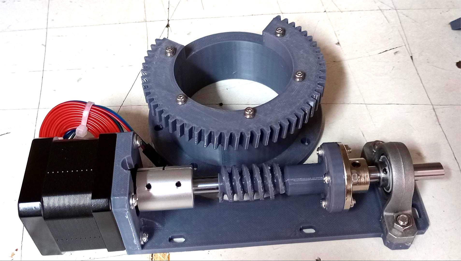
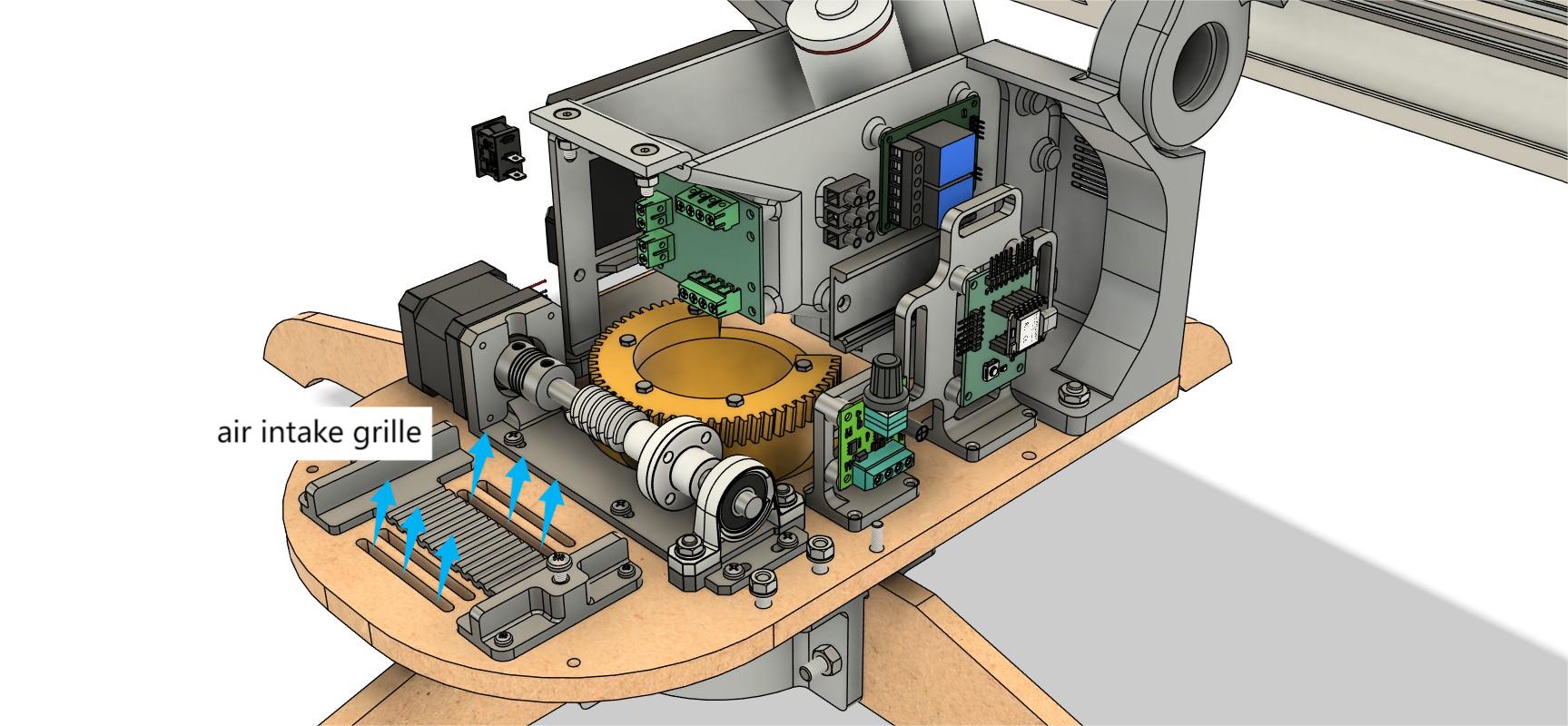
Motion systems (Azimuth & Elevation)
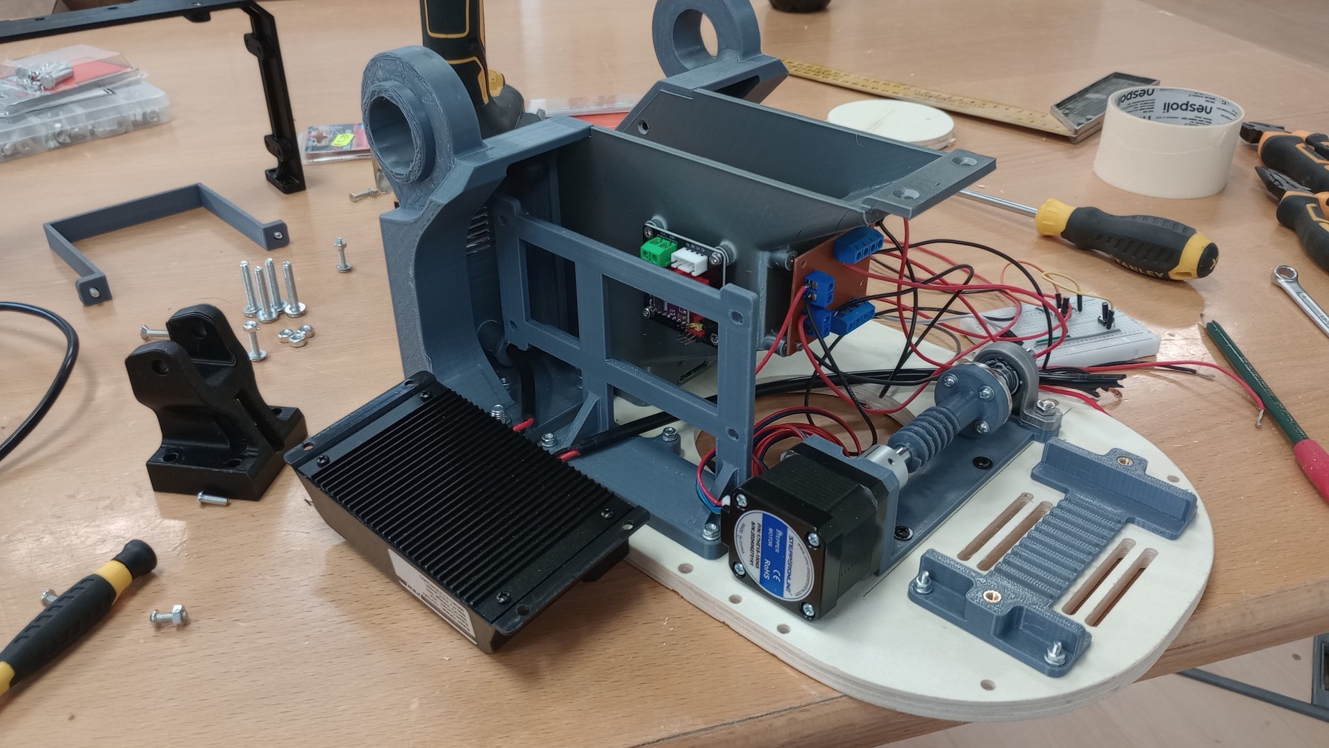
Azimuth motion is achieved with a stepper motor driving a worm gear that connects to a helical gear. This compact transmission provides a high reduction ratio, high output torque, smooth operation, and practical self-locking behavior that resists back-driving from wind loads.
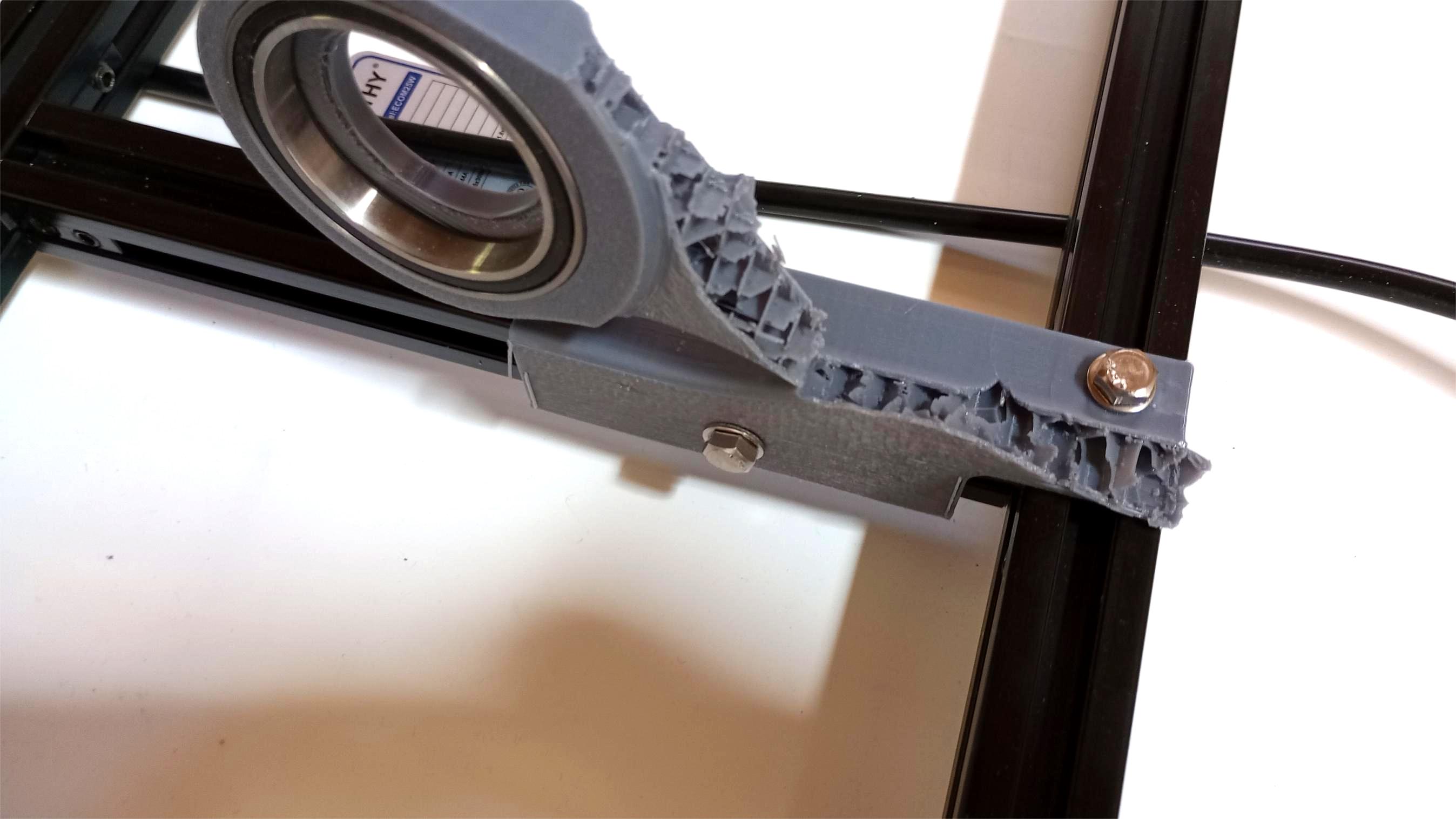
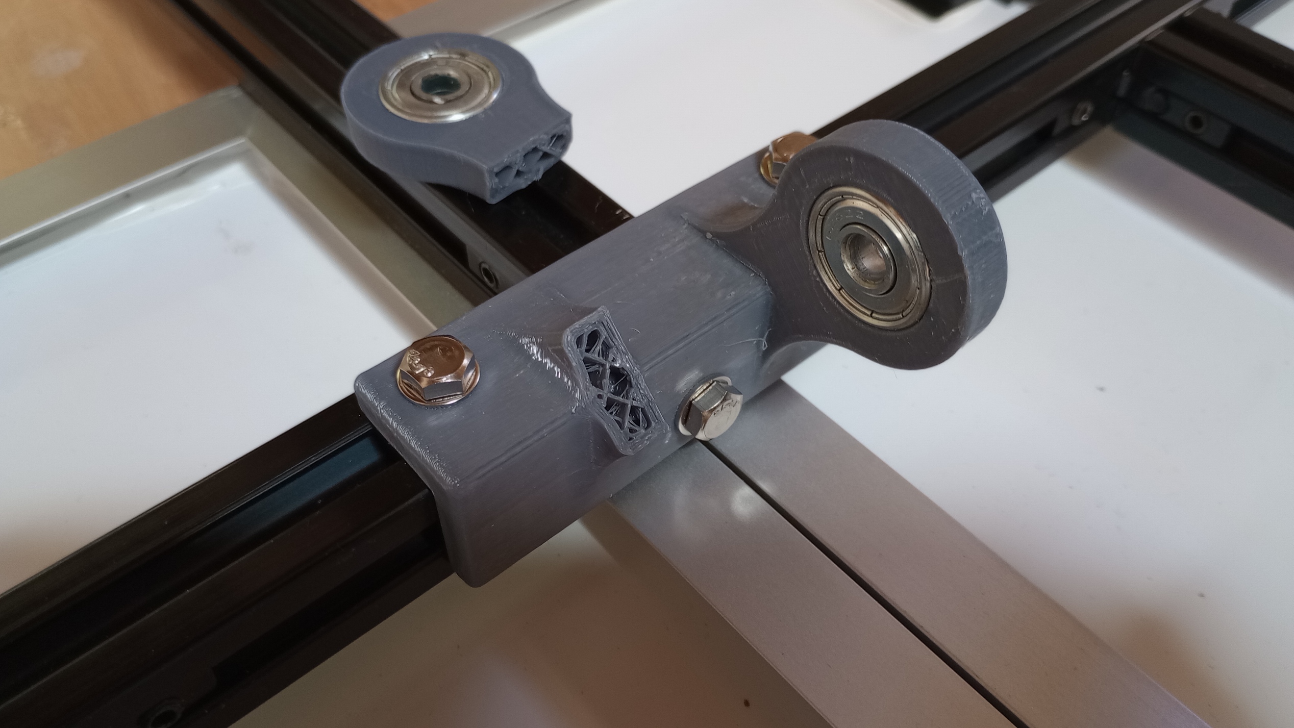
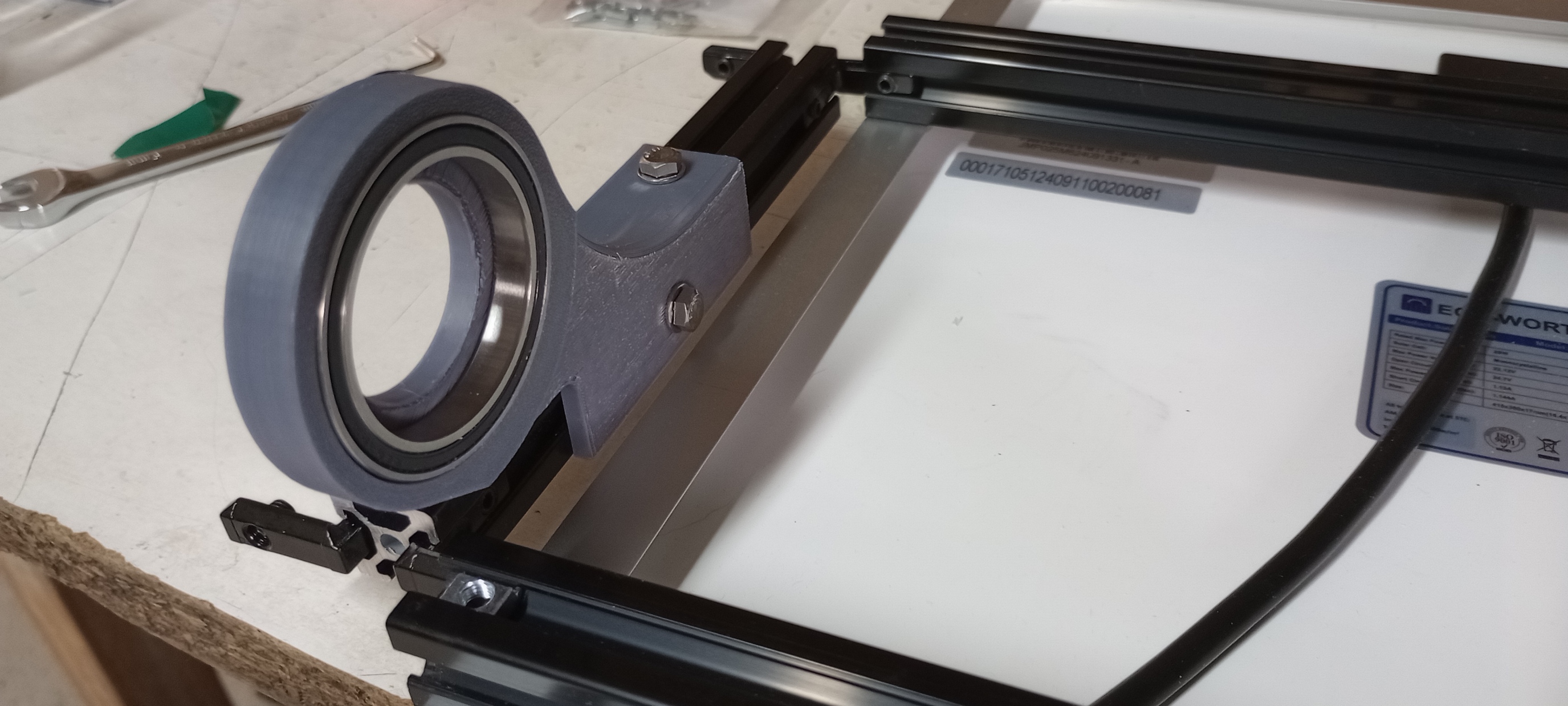
The main axle is coupled to the stepper motor with a flexible coupling to accommodate minor misalignment, damp vibrations, and absorb shocks for more reliable operation. The opposite end of the axle is supported by a ball-bearing block mounted to a 3D-printed bracket that integrates the sub-system. The motor + worm gear mount includes slotted holes for fine alignment to ensure proper gear coupling.
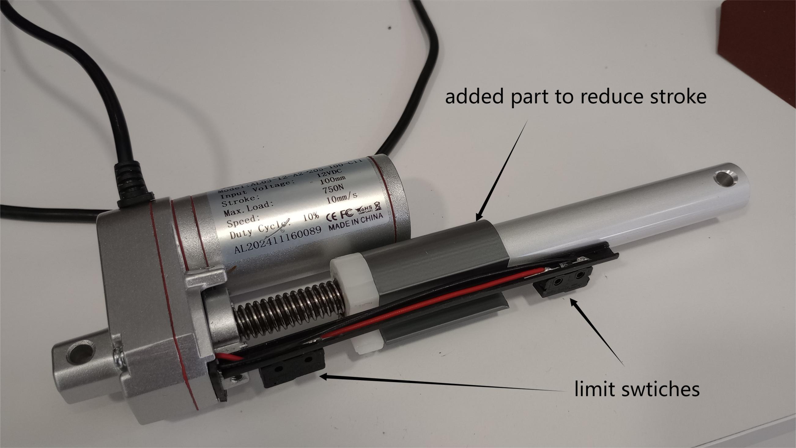
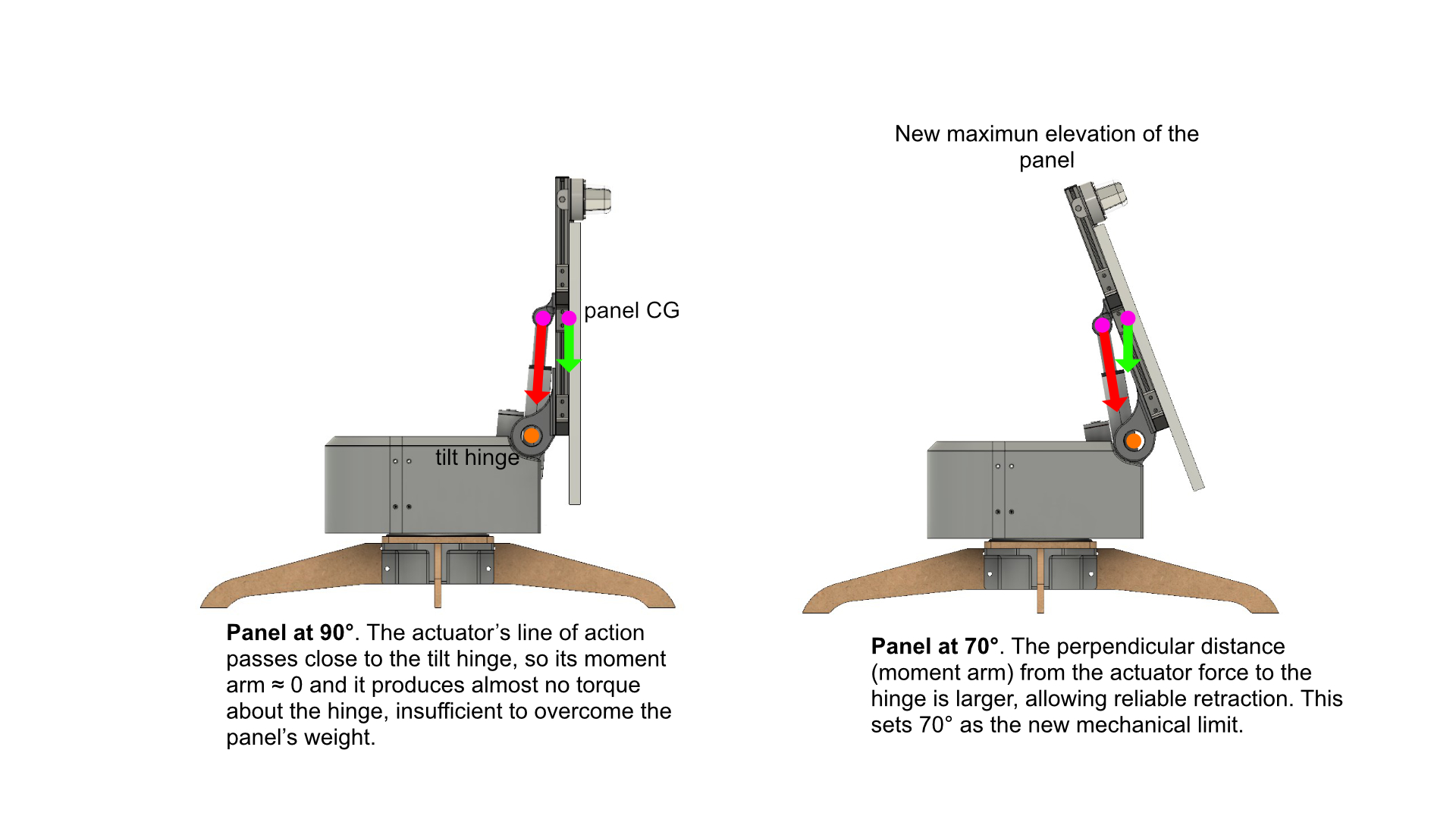
Elevation is achieved with a 12 V linear actuator, with the motor end fixed to the tracker base and the rod end attached to the panel sub-frame. The purchased actuator had a 100 mm stroke, which exceeded the travel needed to go from horizontal to vertical. Rather than adding external limit switches (which would consume extra pins on the microcontroller), I reduced the stroke by inserting a 3D-printed part that activated the internal limit switches.
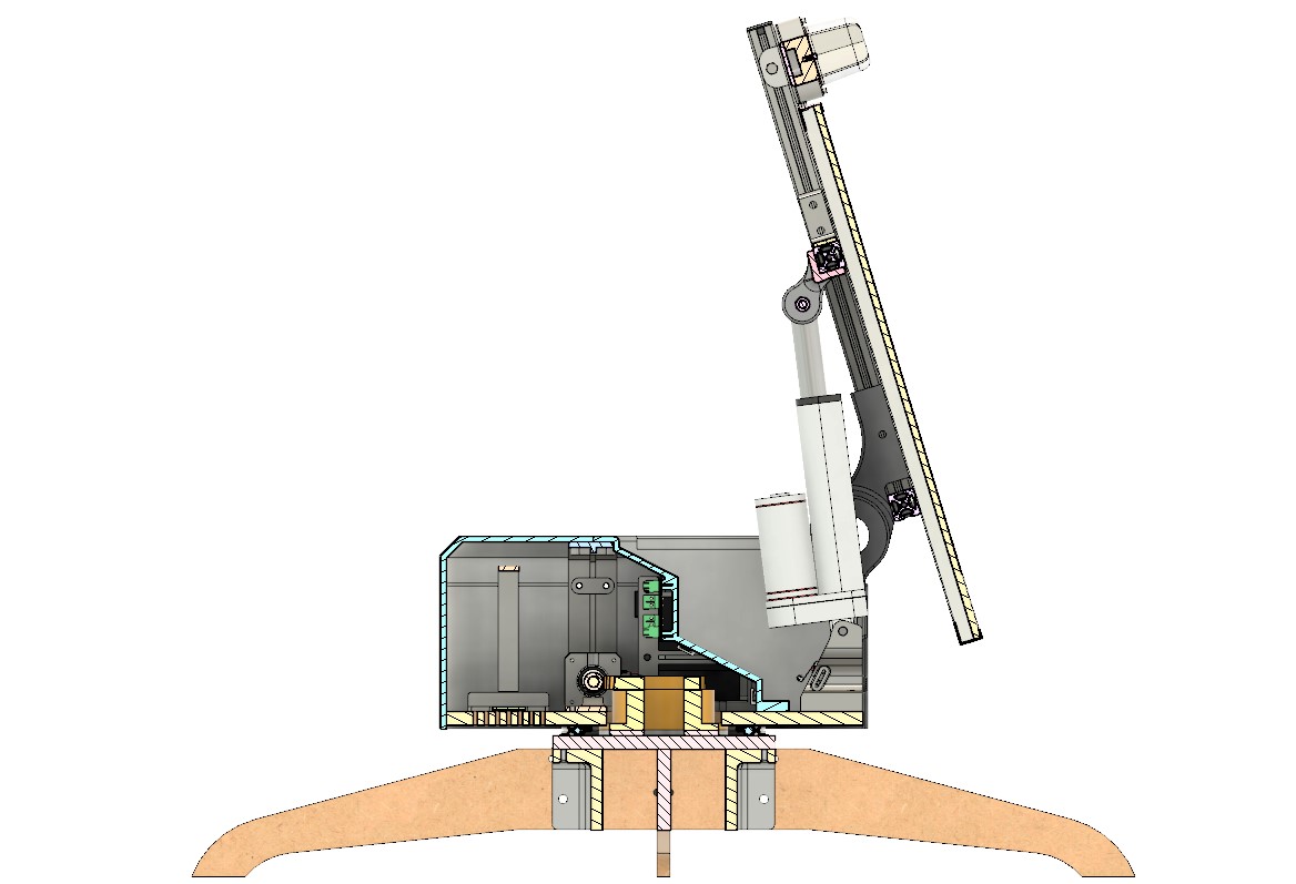
An initial testing allowed the panel to reach a near-vertical position. From that position, retracting the actuator did not tilt the panel back down because the linkage angle was too shallow, producing mostly axial load. This pulled on the panel lugs and broke this part and one hinge.
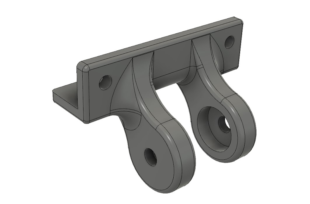
The fix was to limit maximum tilt to around 70° so the actuator always retains a favorable angle to drive the tilt down. The rod-end bracket was also redesigned with thicker lugs and larger fillets to distribute loads and reduce stress concentrations.
 Top
Top
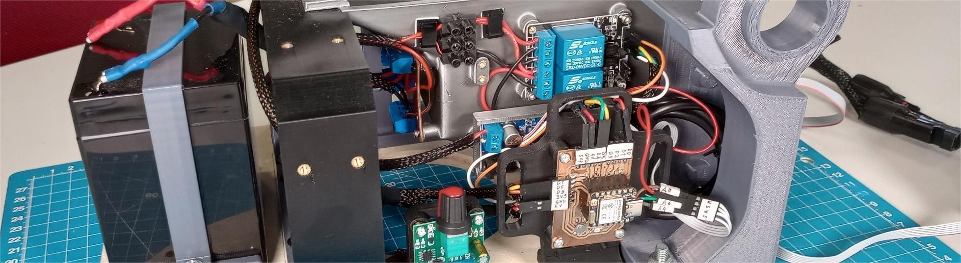
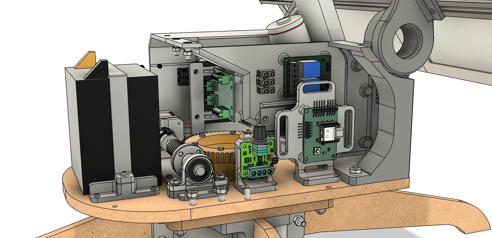
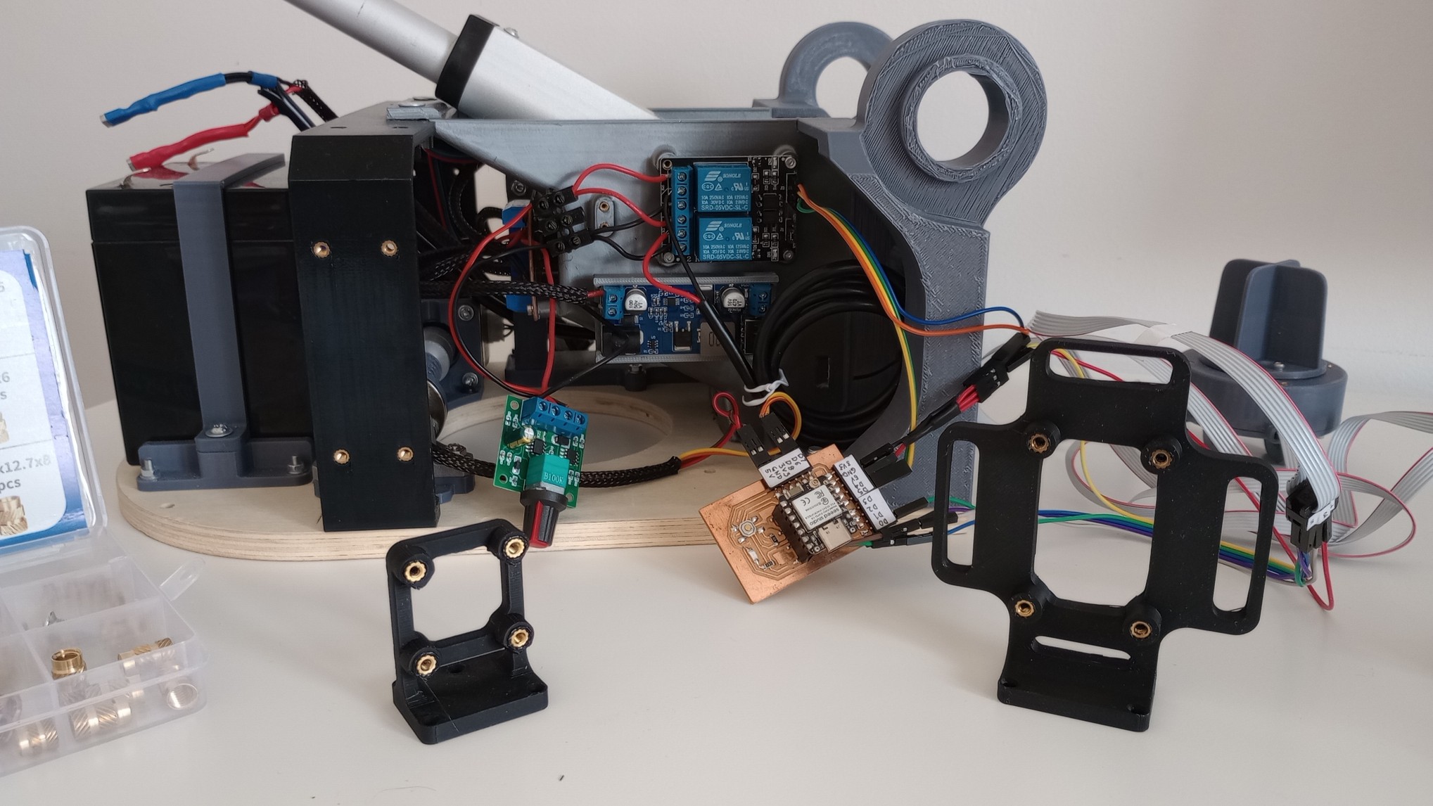
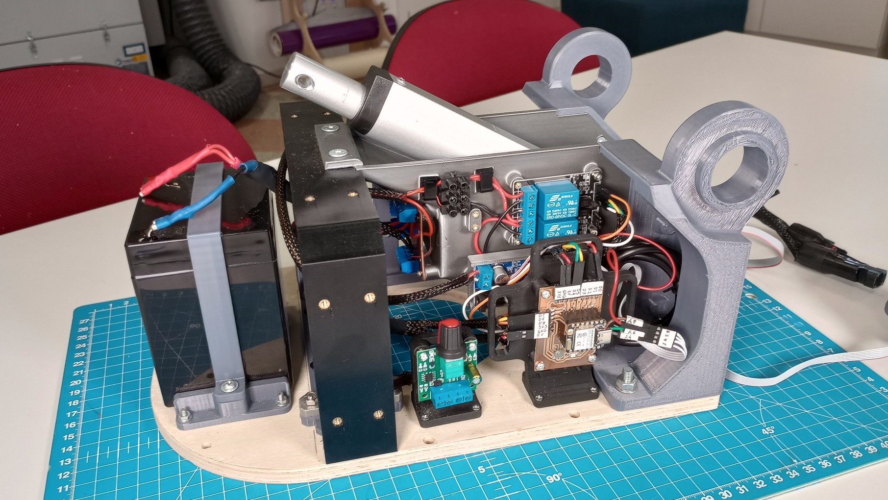
Electronics, sensors and power integration
The following diagram shows the electrical components and their connections
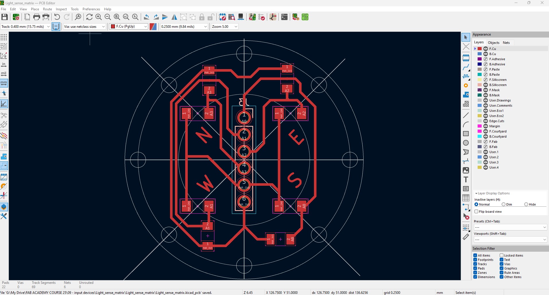
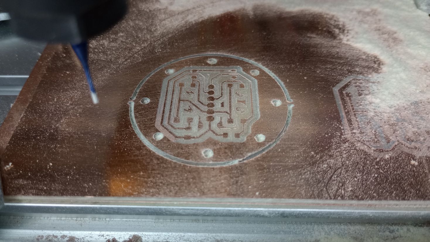
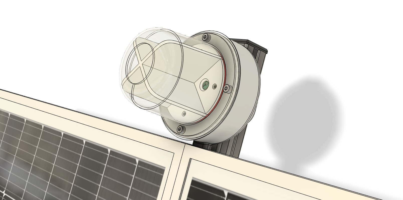
A phototransistor sensor array with baffles provides directional light sensing for tracking. The PCB is circular with four phototransistors and a through-hole pin header on the reverse side. A 3D-printed enclosure with four internal baffles protects the PCB and wiring and mounts to the aluminum T-slot frame.
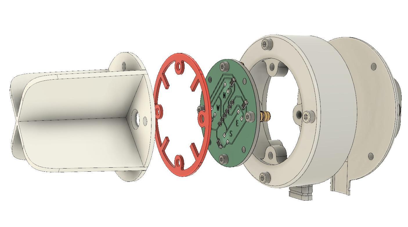
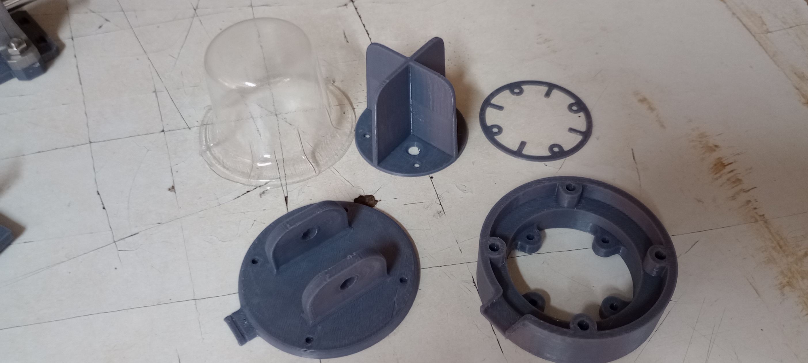
The sensor module is covered by a vacuum‑formed clear PVC cap that admits light while protecting against rain splash.
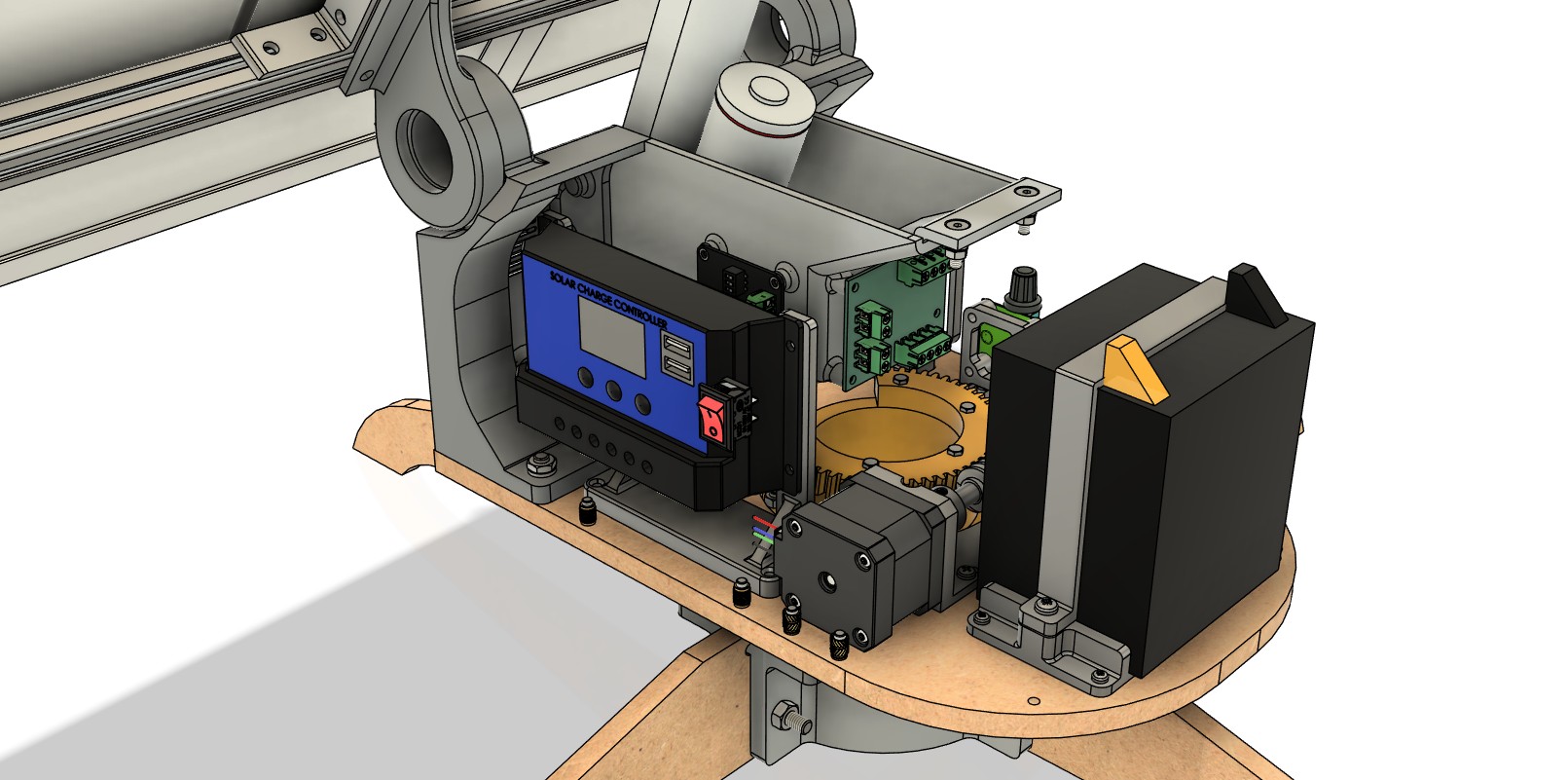
Power system
- PV panels feed a 12 V solar charge controller that charges a 12 V LiFePO4
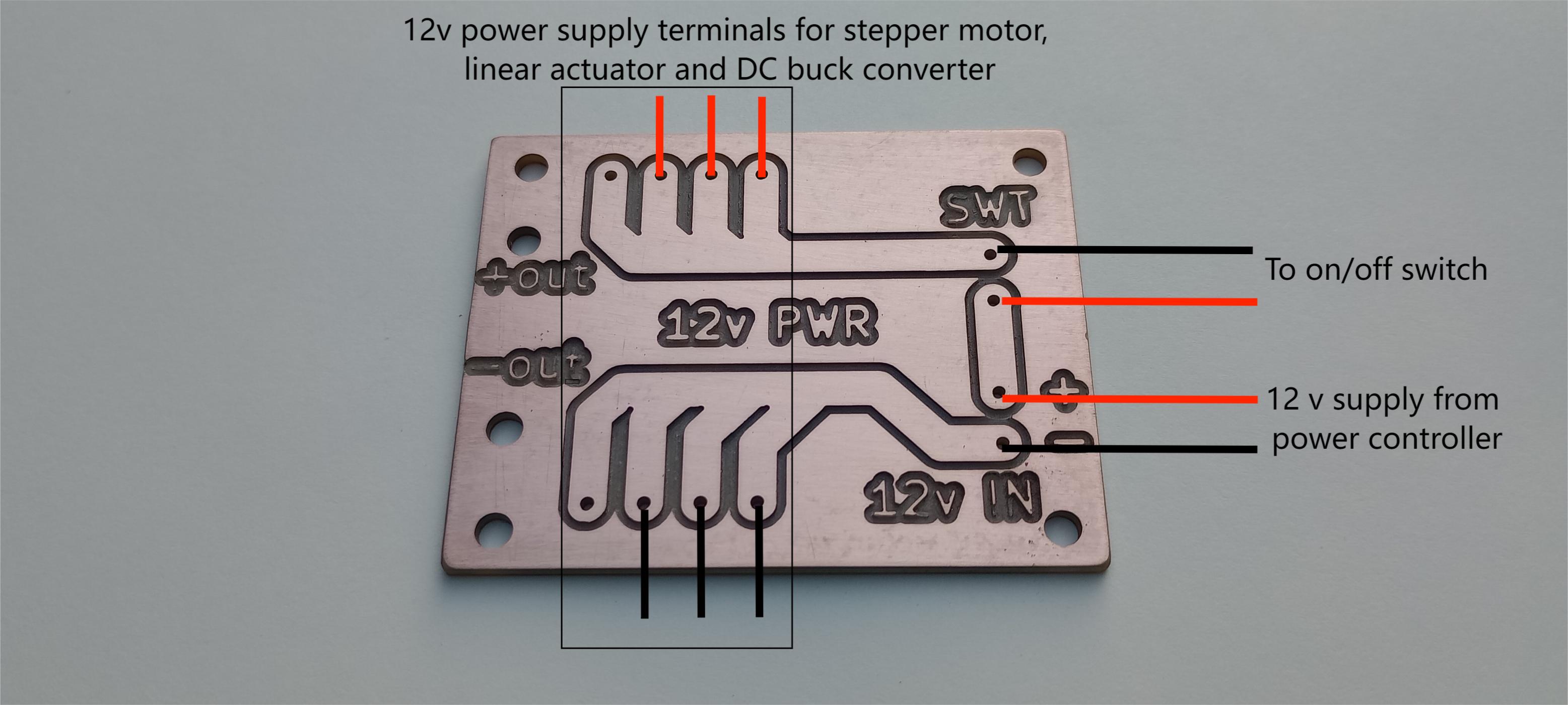
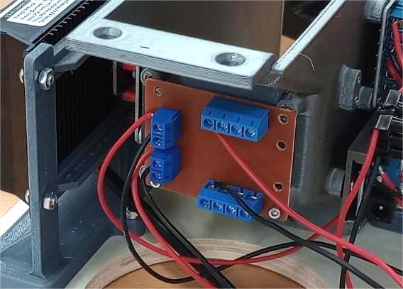
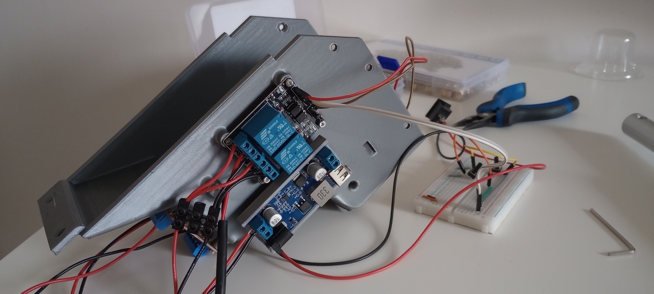
- A custom power distribution PCB provides terminal blocks for the linear actuator and stepper motor.
- A 12Vto 5V buck converter powers the microcontroller and low-voltage electronics.
- MC4 connectors are used on PV leads for sealed, locking connections.
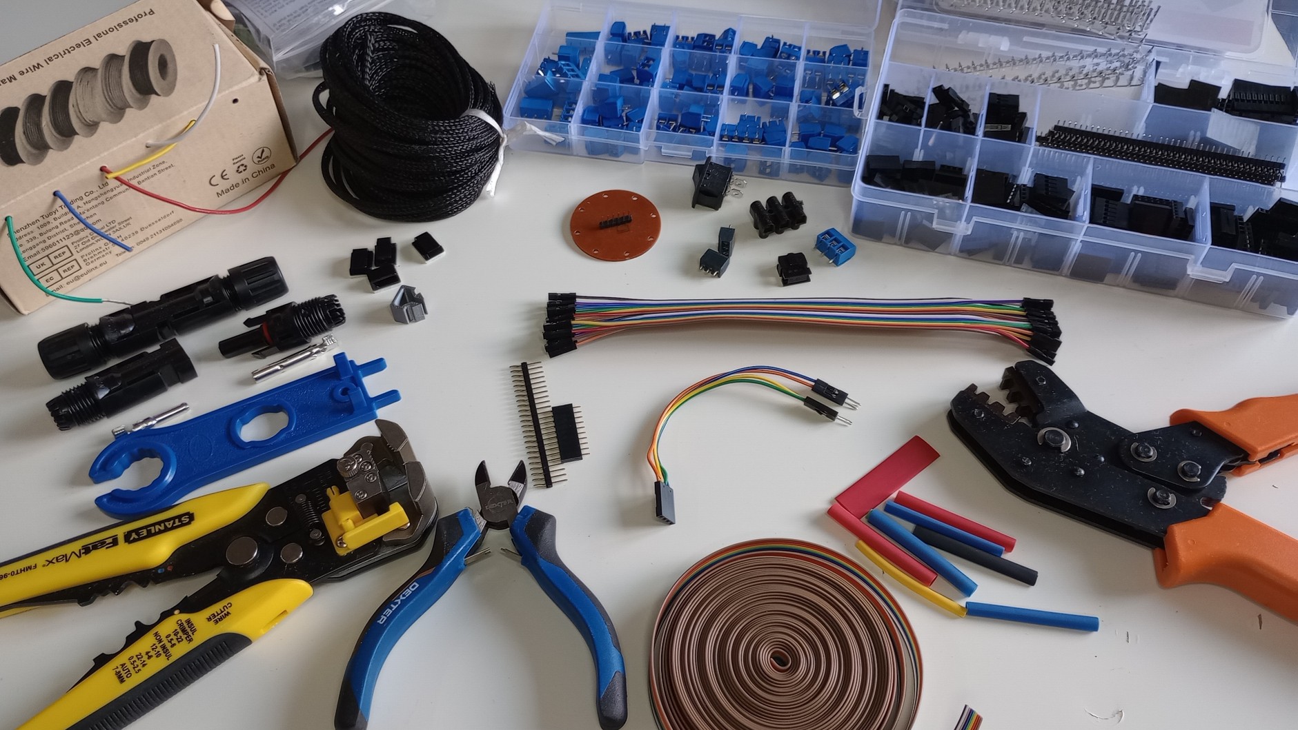
Wiring
- Terminal blocks for off-the-shelf modules and the power PCB.
- Spade terminals for battery connections.
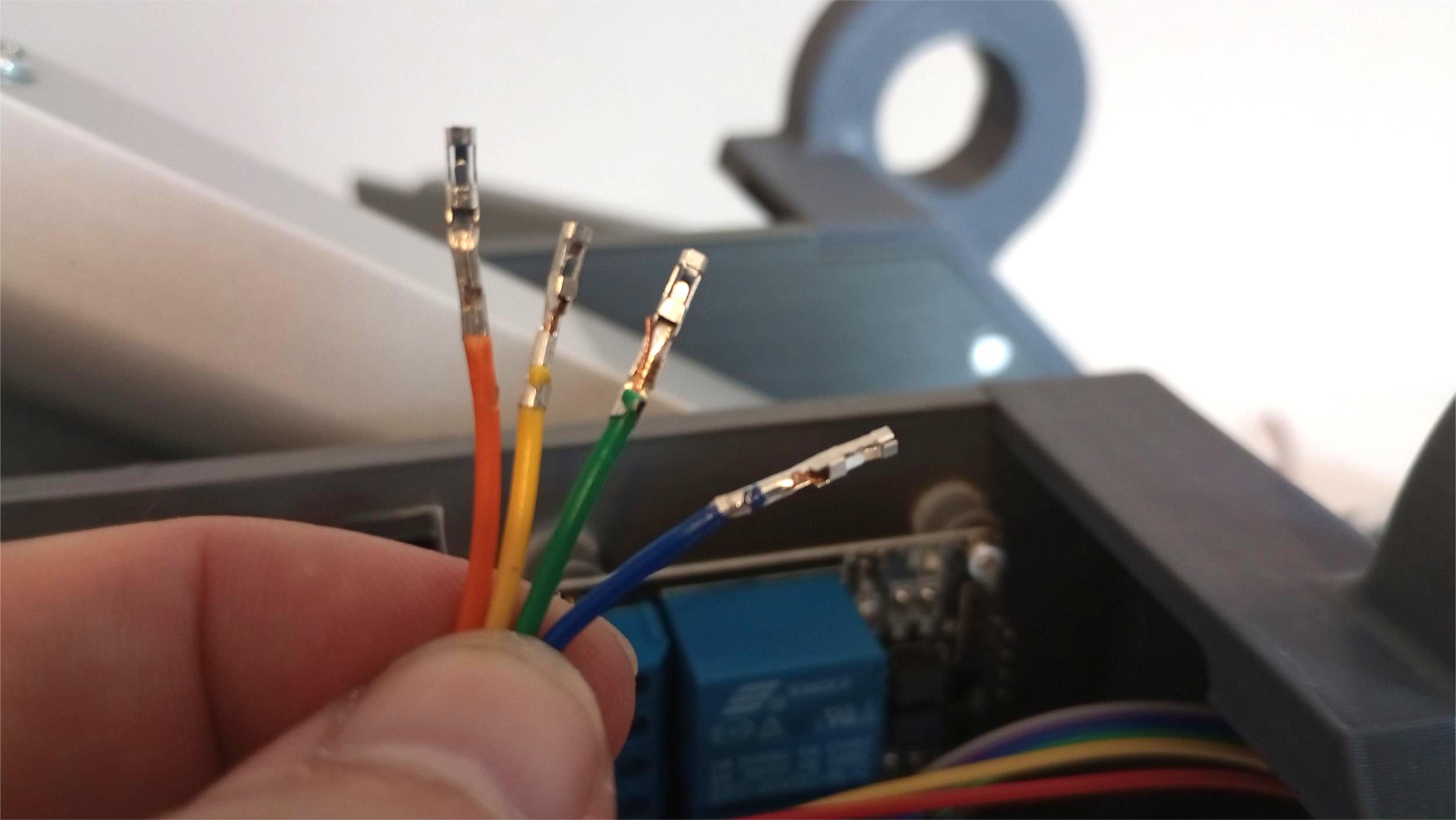
- Jumper wires to board headers (microcontroller and sensor).
- Harnessing with heat-shrink, braided sleeve, and adhesive cable clips for routing.
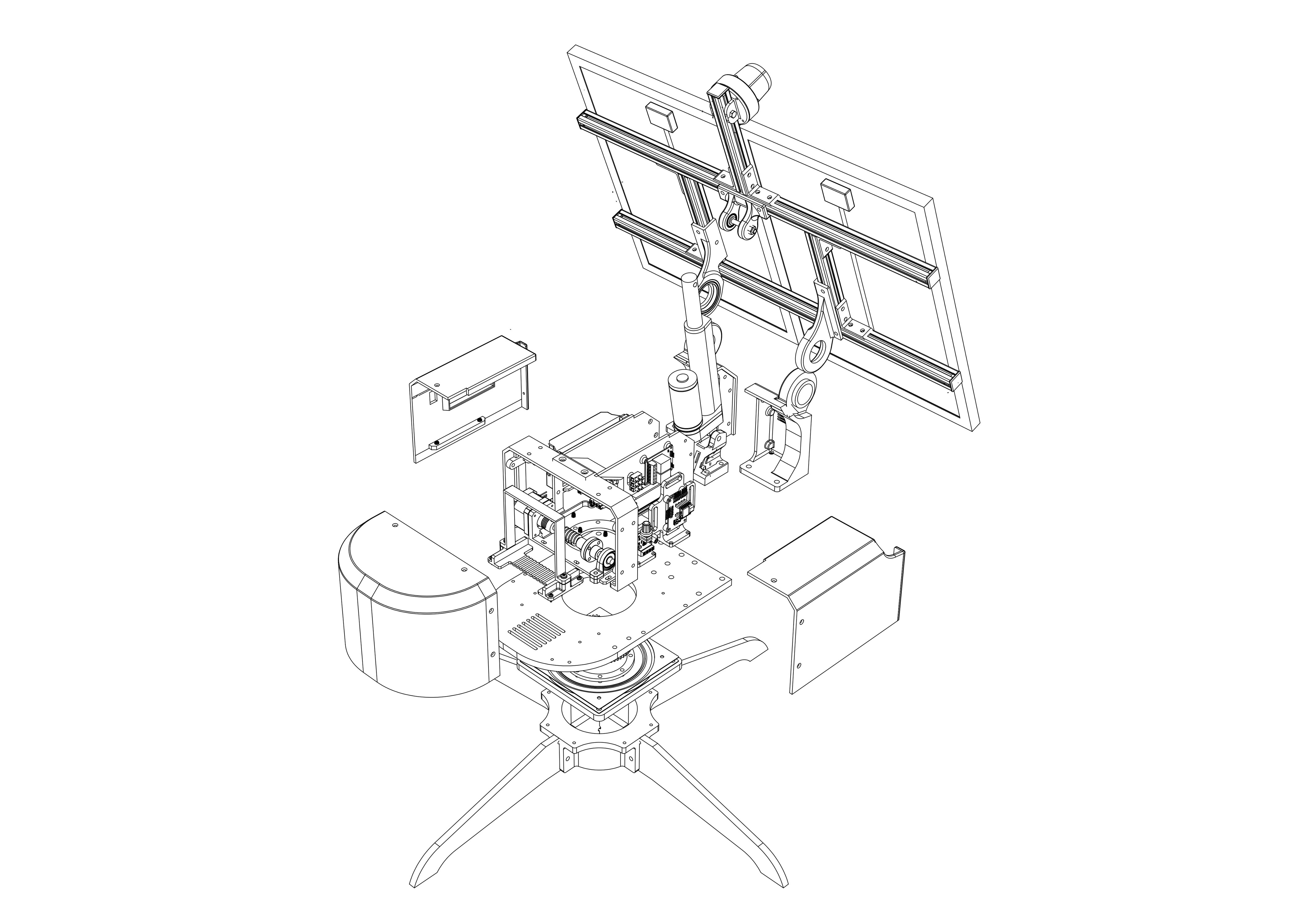
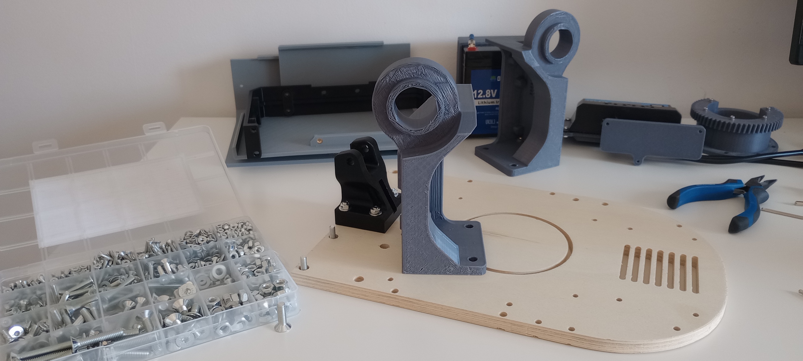
Mechanical integration & fabrication
The structure is divided into three sub-assemblies:
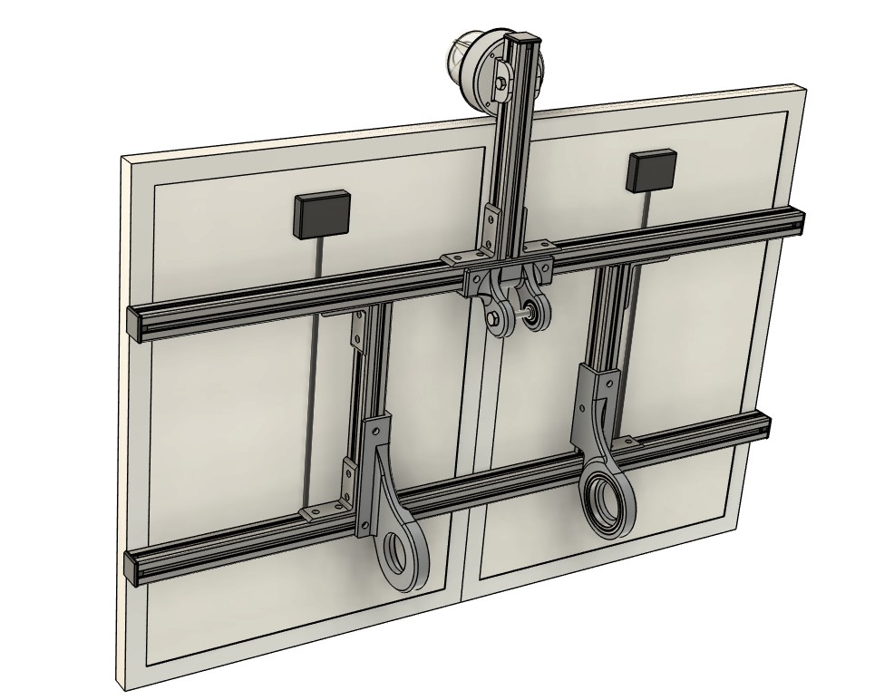
- Panel assembly:PV panels, aluminum sub-frame, sensor array, hinges, and actuator lugs.
- Enclosure:electronics and powertrain (wiring, battery, actuator, stepper, gear train), internal supports, and outer panels.
- Base & legs:a ball-bearing turntable base with detachable legs.
The panels mount to an aluminum 2020 T-slot frame joined with corner connectors. Hinges, brackets, and the sensor are fastened with T-nuts and bolts.
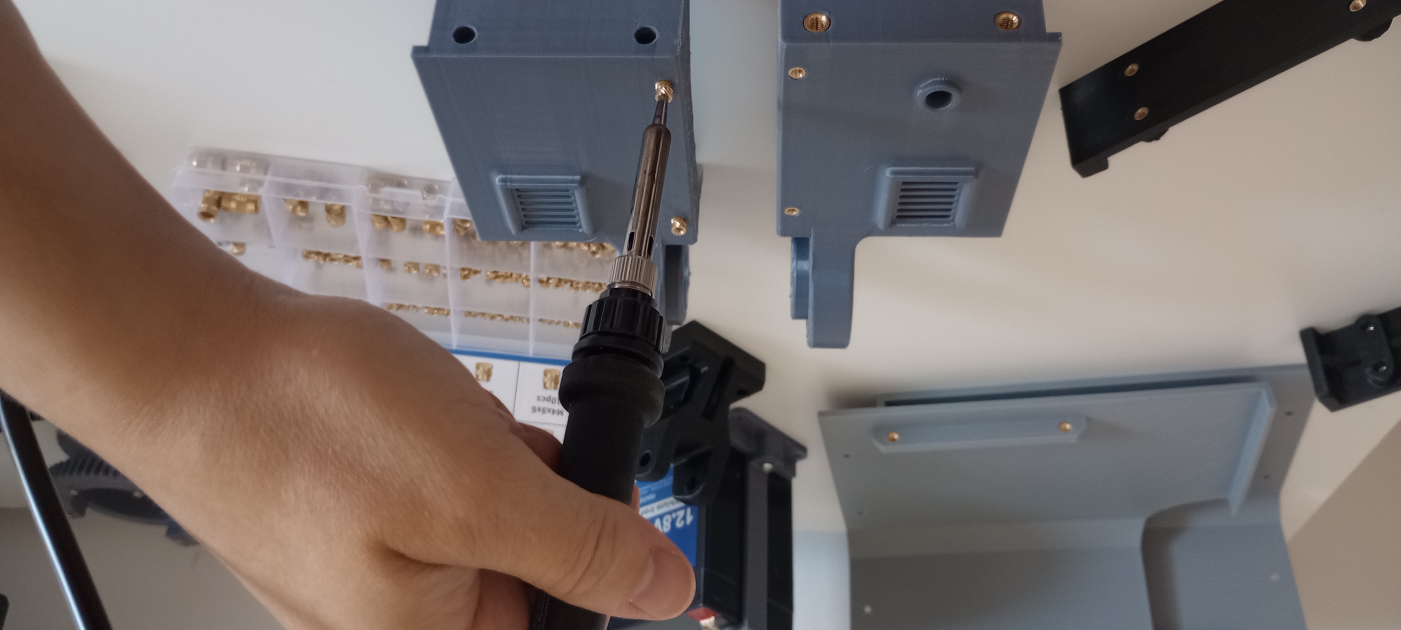
The enclosure was sized to house all electronics with clear access once the outer covers are removed. Each module has a dedicated mounting frame or uses integrated bosses; parts are fixed to a 10 mm plywood base with self-tapping screws (small parts) or bolts/nuts for higher loads. Many fasteners are countersunk to keep the base surface flush. Heat threaded inserts are used in 3D-printed parts for durable threads.
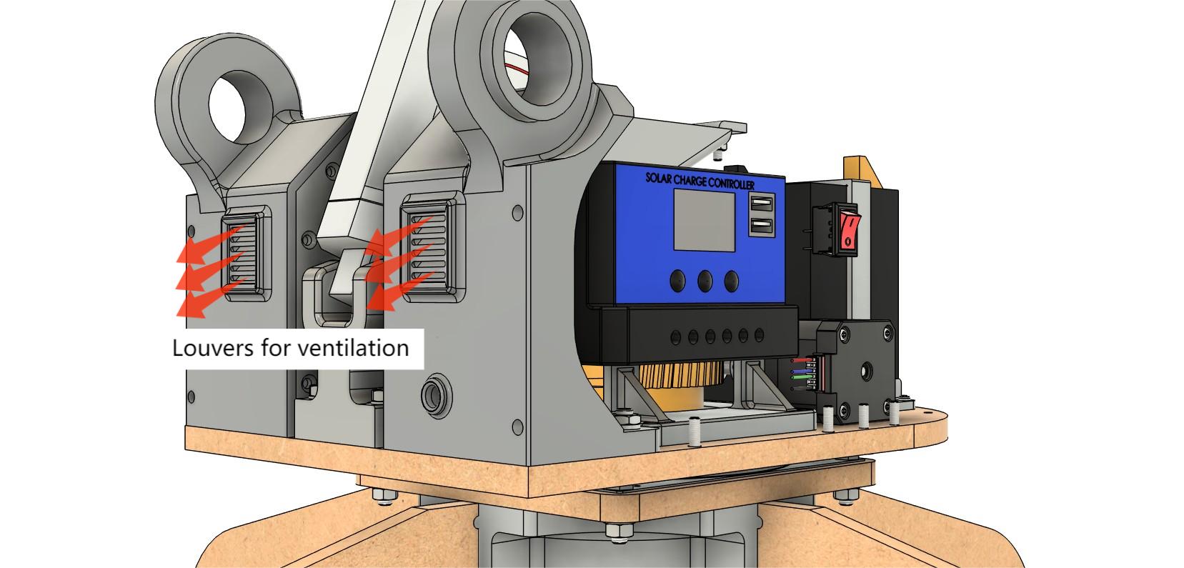
Safety and maintenance
The tracker runs short, slow cycles every 10–15 minutes. The only exposed moving element is the linear actuator; due to the low speed, pinch point risk is minimal. Guards are therefore not necessary for the current prototype.
Serviceability is achieved by removing three outer panels to expose the electronics and connectors. For outdoor operation, passive ventilation slots at the base and louvered exhaust openings were added to reduce heat buildup while minimizing water ingress risk.
Top