Week 04. Embedded Programming
Table of Contents
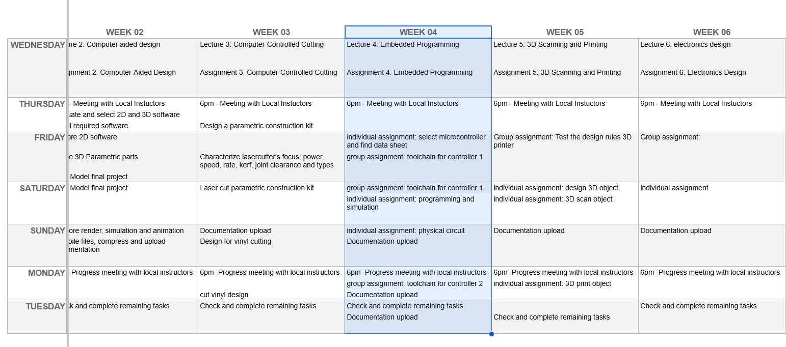
- WEEKLY PLAN
- GROUP ASSIGNMENT: toolchains and development workflows of embedded architecture
- INDIVIDUAL ASSIGNMENT
- EMBEDDED PROGRAMMING: CONTRIBUTION TO FINAL PROJECT
- USEFUL LINKS AND RESOURCES
- FILES
WEEKLY PLAN
Group assignment
- Demonstrate and compare the toolchains and development workflows for available embedded architectures
- Document your work to the group work page and reflect on your individual page what you learned.
Individual assignment
- Browse through the datasheet for your microcontroller
- Write a program for a microcontroller, and simulate its operation, to interact (with local input &/or output devices) and communicate (with remote wired or wireless connection)
GROUP ASSIGNMENT: toolchains and development workflows of embedded architecture
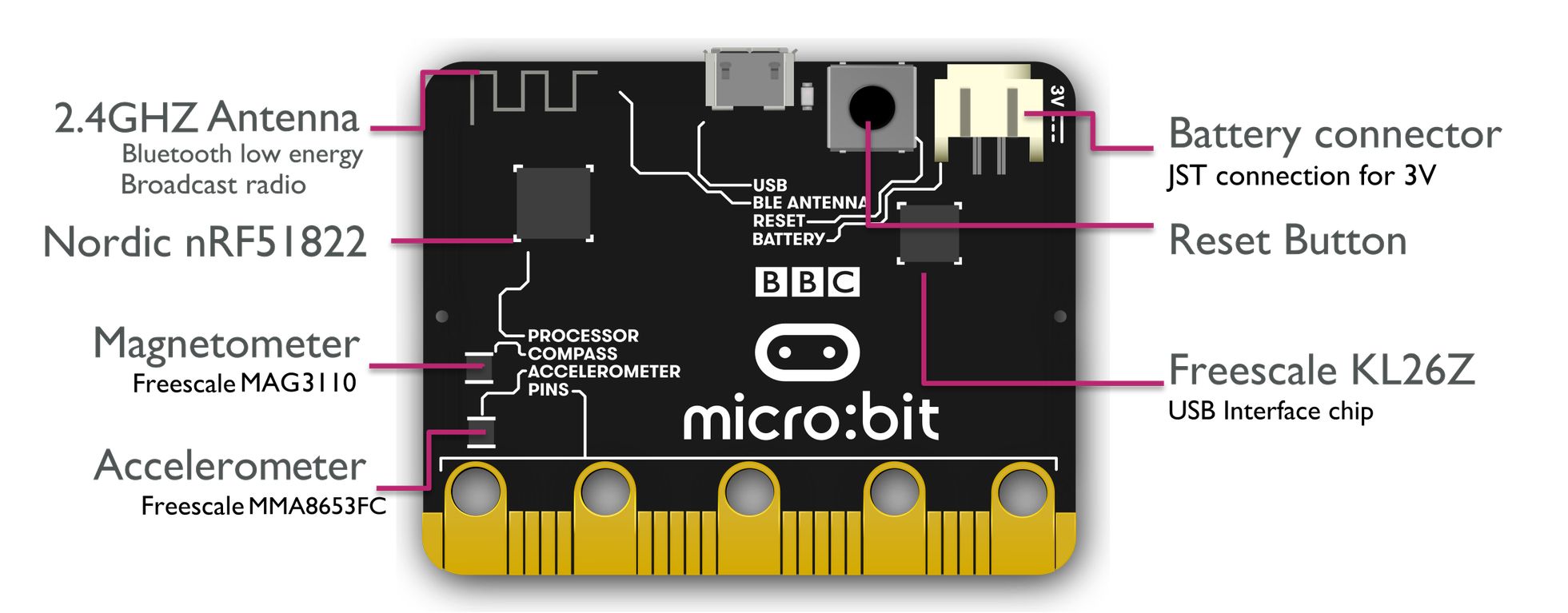
Toolchains for Micro:Bit (v1)
Micro:bit is an open source hardware ARM-based embedded system very popular for use in computer education, specially in the UK, as it was designed by the BBC and initially delivered for free to public schools.
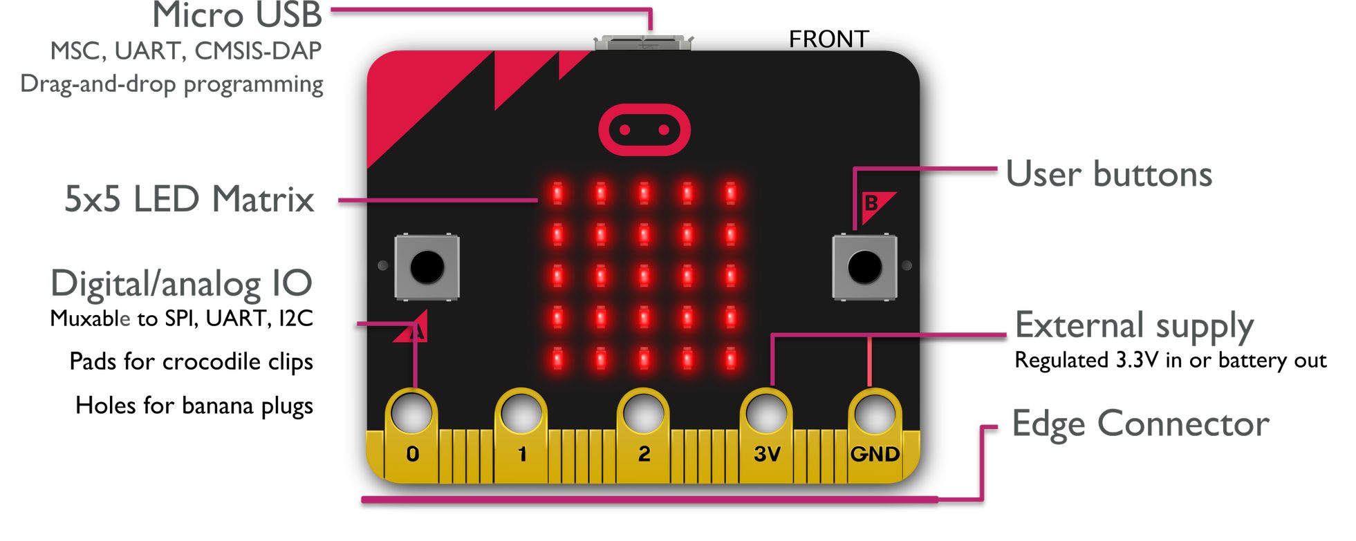
The micro:bit can be coded using the Microsoft Makecode, a web-based code editor that uses blocks, Python and Java Script.
Detailed hardware information can be found in this link: https://tech.microbit.org/hardware/1-3-revision/
The controller of the micro:bit board V1 is the nRF51822 microcontroller, from Nordic Semiconductor. It is based on a 32-bit ARM Cortex-M0 processor.
Here are some key specifications for the micro:bit V1's controller:
|
item |
details |
|
Model |
|
|
Core variant |
|
|
Flash ROM |
256KB |
|
RAM |
16KB |
|
Speed |
16MHz |
Since I have several micro:bits (v1) around I decided to find out about the toolchain set up required to code it using the Aruino IDE (C++) and Thonny IDE (MicroPython).
Micro:bit toolchain for Arduino IDE
I have Arduino IDE installed, so the first step is to add the Micro:bit board support. I go to File > Preferences and in the Additional Boards Manager URLs field, I add this URL for Micro:bit board support:
https://sandeepmistry.github.io/arduino-nRF5/package_nRF5_boards_index.json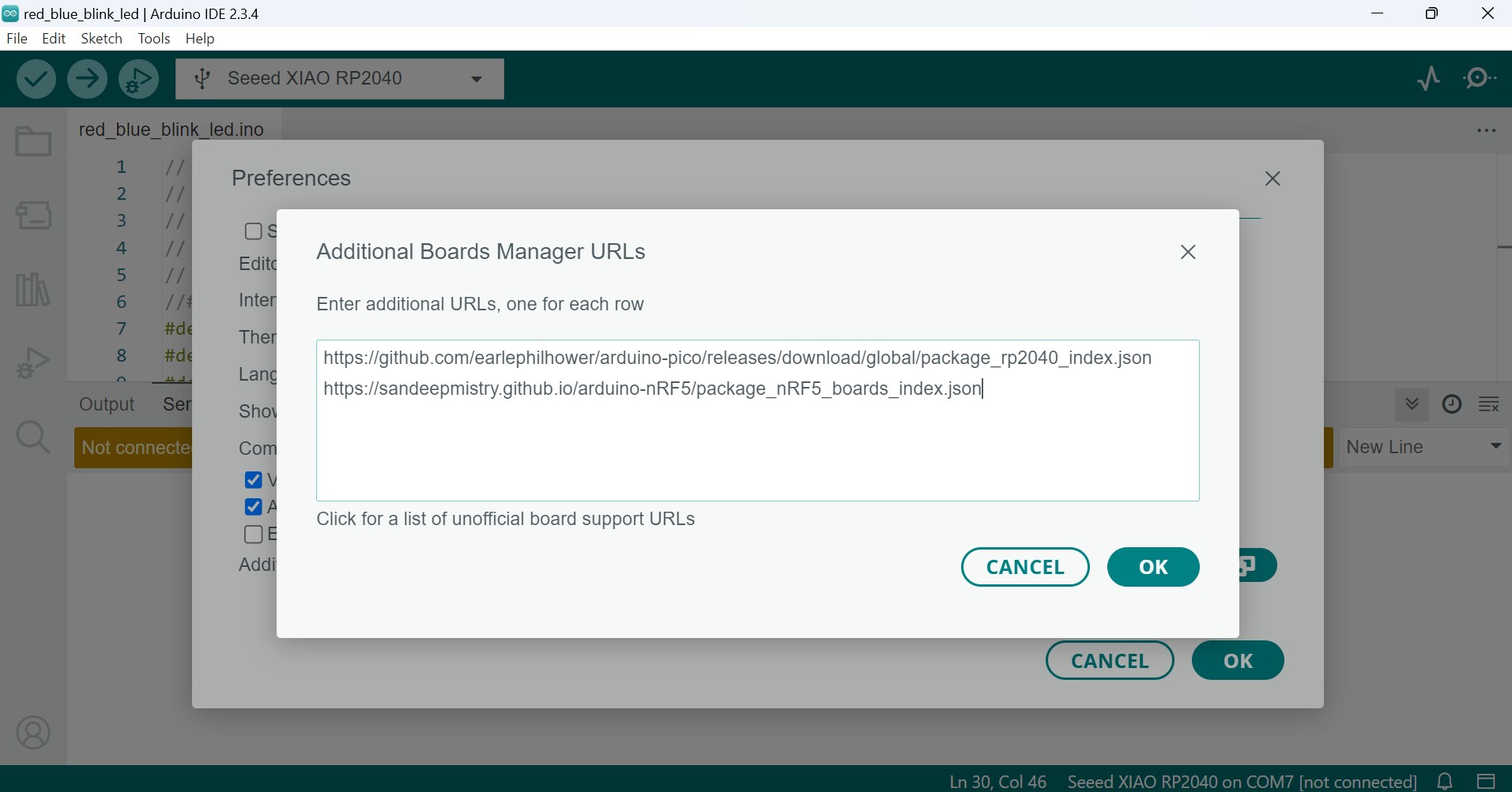
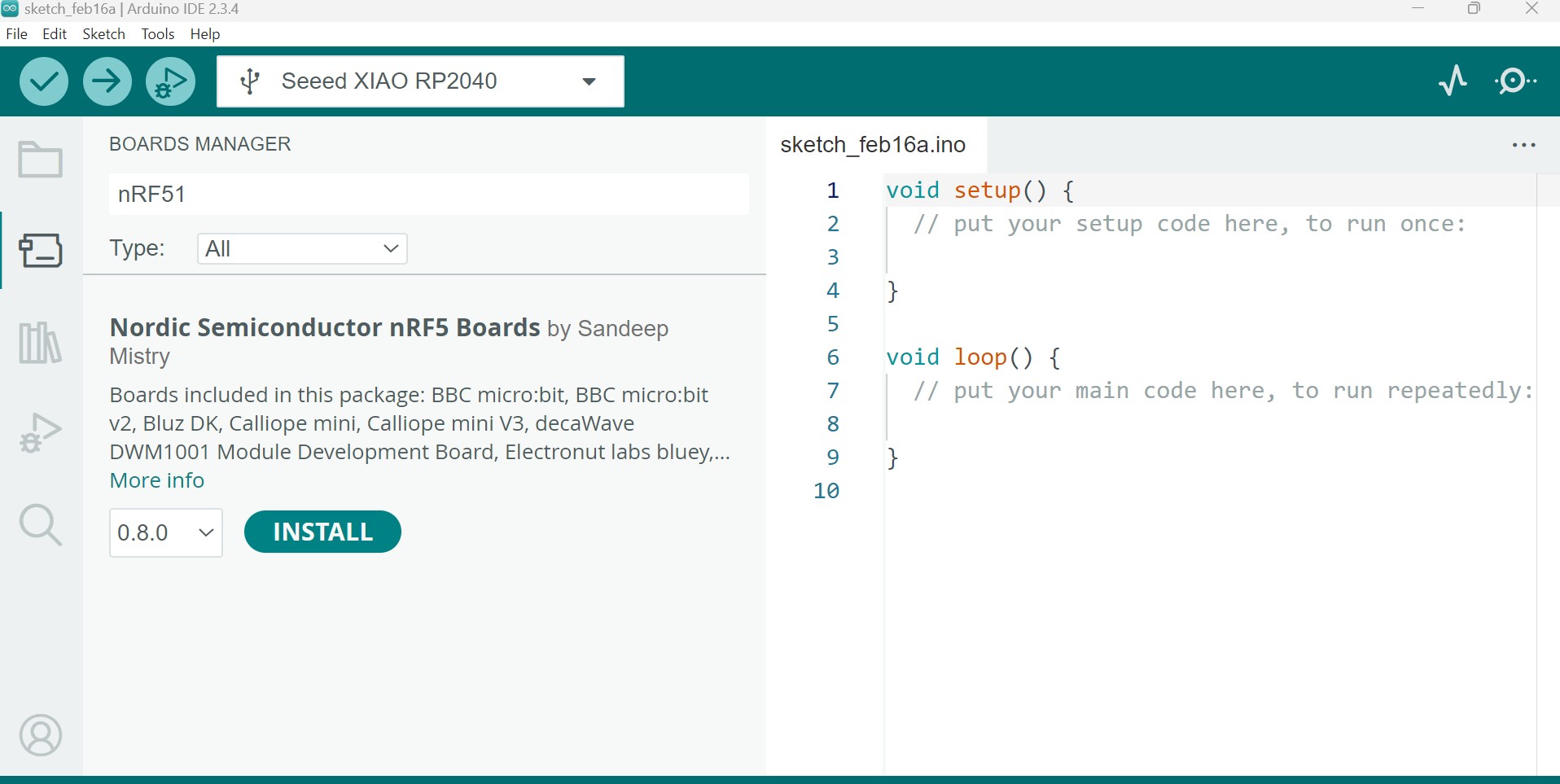
Then I go to Tools > Board > Board Manager, search for "nRF51", and install the package "Nordic Semiconductor nRF5 Boards".
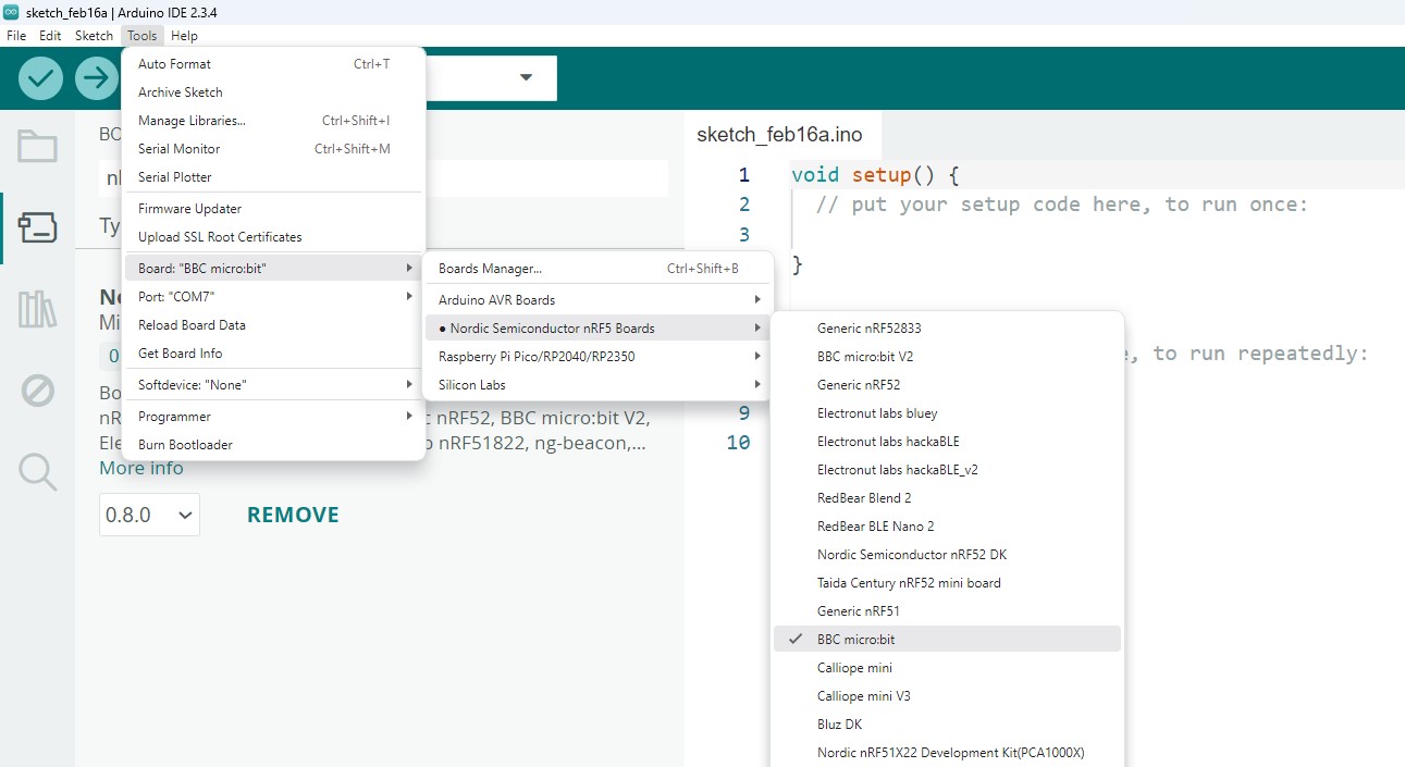
In tools>Board, I select Nordic Semiconductor nRF5 Boards>BBC microbit.
I connect the microbit using a microUSB cable and I select the correct port (COM8 Serial Port (USB)).
I can now write a program for the microbit in the Arduino IDE as I would for any Arduino board, using the familiar functions like setup(), loop(), and hardware interfaces (buttons, LEDs, etc.).
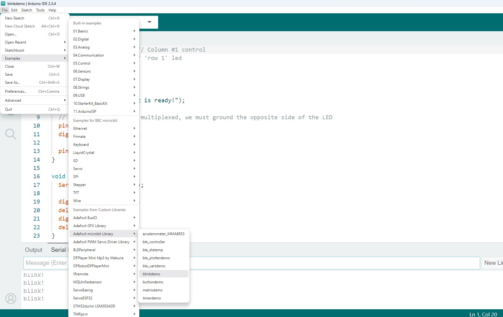
To check that the toolchain set up works I use the “Adafruit microbit Library” example “blinkdemo”.
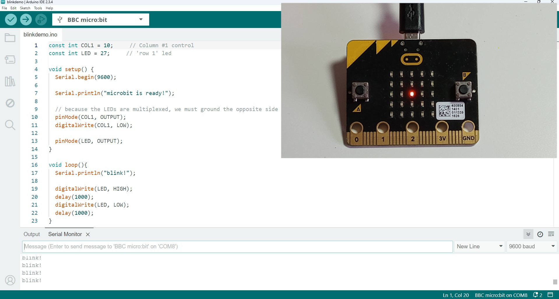
I modified the the LED columns and row so the LED in the centre turns on. The LED blinks every second and the serial monitor prints “blink!”.
blinkdemo_microbit.ino
const int COL1 = 10;     // Column #1 control
const int LED = 27;     // 'row 1' led

void setup() {
  Serial.begin(9600);

  Serial.println("microbit is ready!");

  // because the LEDs are multiplexed, we must ground the opposite side of the LED
  pinMode(COL1, OUTPUT);
  digitalWrite(COL1, LOW);

  pinMode(LED, OUTPUT);
}
void loop(){
  Serial.println("blink!");

  digitalWrite(LED, HIGH);
  delay(1000);
  digitalWrite(LED, LOW);
  delay(1000);
}
Microbit toolchain for Thonny (MicroPython)
I install Thonny IDE which comes with Python 3.10 built in.
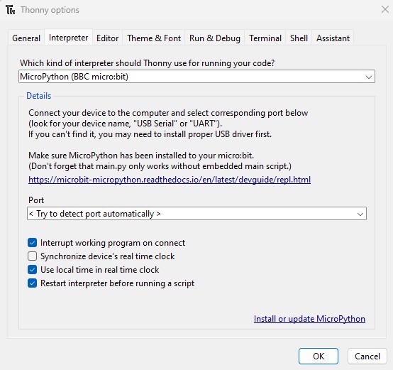
With the Microbit plugged in, in Thonny ,I go to Tools > Options > Interpreter.
I choose MicroPython (BBC micro:bit) as the interpreter and I select the correct port.
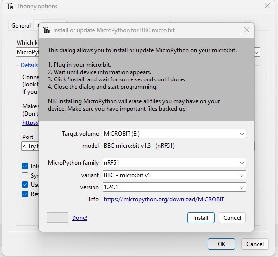
The Microbit runs MicroPython. From Thonny I update MicroPython firmware for the Microbit.
In Thonny, I write a MicroPython code using commands to make the central LED blink. I click the Run button in Thonny to upload the code to the Microbit.
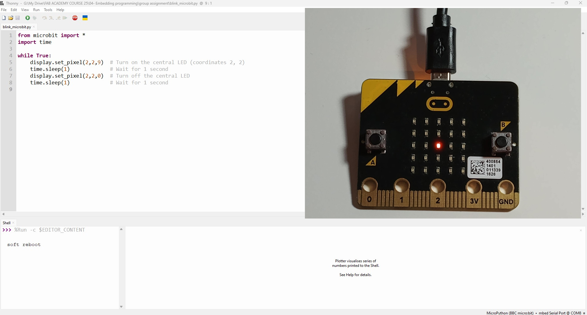
blink_microbit.py
from microbit import *
import time

while True:
    display.set_pixel(2,2,9)  # Turn on the central LED (coordinates 2, 2)
    time.sleep(1)             # Wait for 1 second
    display.set_pixel(2,2,0)  # Turn off the central LED
    time.sleep(1)             # Wait for 1 second
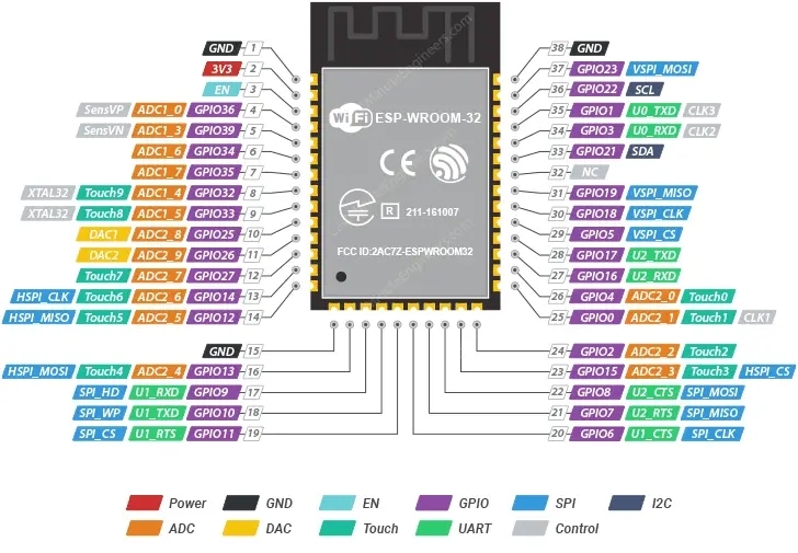
Toolchains for ESP32 WROOM
The ESP32-WROOM is a powerful Wi-Fi and Bluetooth module developed by Espressif Systems. It is designed for a wide range of applications, including IoT, home automation, wearable devices, smart agriculture, etc. The module integrates both Wi-Fi and Bluetooth (classic and Low Energy), making it versatile for wireless communication.
ESP32 toolchain for Arduino IDE
The steps to develop code for the ESP32 using the Arduino ID are similar to the steps explained for the Micro:bit.
I followed the installation steps indicated by Espressif in this link. In the Arduino IDE I navigate to File > Preferences. In the "Additional Boards Manager URLs" field, I added the following URL:
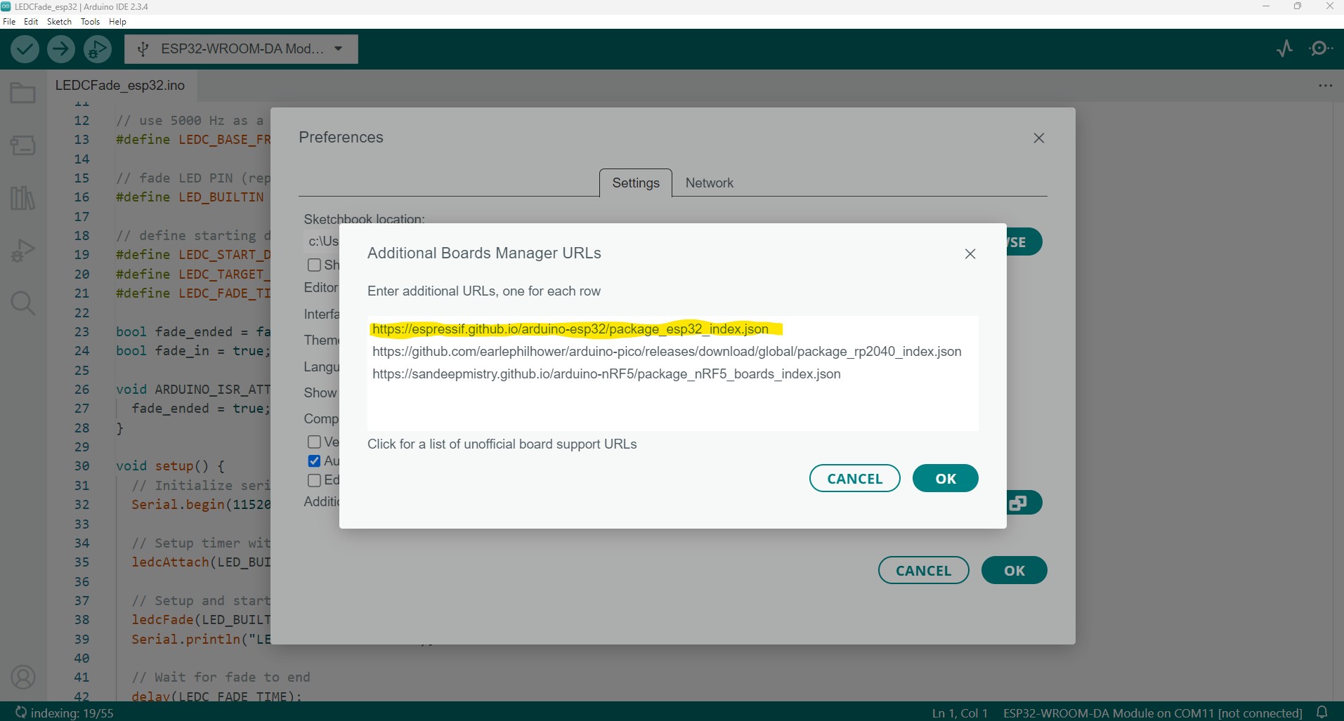
Then I install the ESP32 Board package in Arduino ID. In Tools > Board > Boards Manager, I search for "ESP32" and I install the "ESP32 by Espressif Systems".
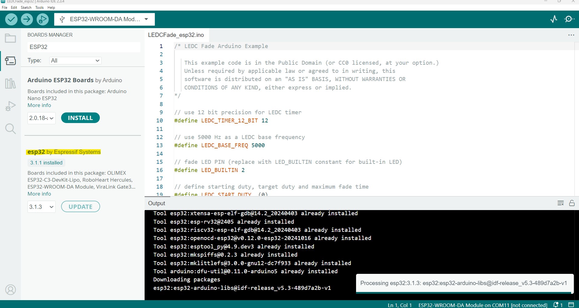
Then, with the board connected to my computer I go to Tools>Board and I choose the appropriate ESP32 module and the PORT associated.
To test it I go to examples and from the ESP32 selection, I load the LEDCFade.ino example. In the code I change the LED pin to LED_BUILTIN 2 so the in-built led turns on. I compile and upload the program to the ESP32, and after a while I see that it works.
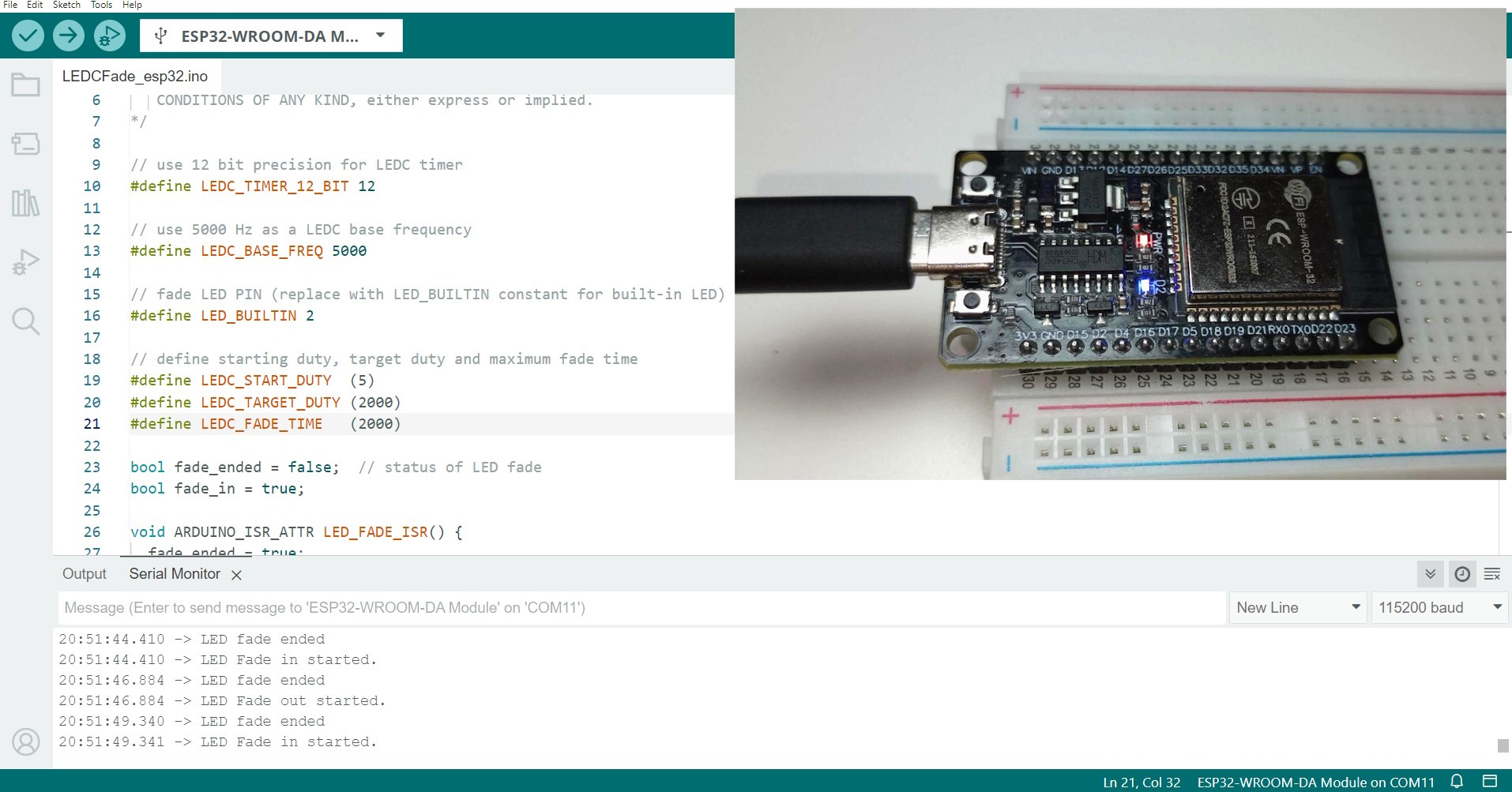
LEDCFade_esp32.ino
// use 12 bit precision for LEDC timer
#define LEDC_TIMER_12_BIT 12

// use 5000 Hz as a LEDC base frequency
#define LEDC_BASE_FREQ 5000

// fade LED PIN (replace with LED_BUILTIN constant for built-in LED)
#define LED_BUILTIN 2

// define starting duty, target duty and maximum fade time
#define LEDC_START_DUTY  (5)
#define LEDC_TARGET_DUTY (2000)
#define LEDC_FADE_TIME   (2000)

bool fade_ended = false;  // status of LED fade
bool fade_in = true;

void ARDUINO_ISR_ATTR LED_FADE_ISR() {
  fade_ended = true;
}

void setup() {
  // Initialize serial communication at 115200 bits per second:
  Serial.begin(115200);

  // Setup timer with given frequency, resolution and attach it to a led pin with auto-selected channel
  ledcAttach(LED_BUILTIN, LEDC_BASE_FREQ, LEDC_TIMER_12_BIT);

  // Setup and start fade on led (duty from 0 to 4095)
  ledcFade(LED_BUILTIN, LEDC_START_DUTY, LEDC_TARGET_DUTY, LEDC_FADE_TIME);
  Serial.println("LED Fade on started.");

  // Wait for fade to end
  delay(LEDC_FADE_TIME);

  // Setup and start fade off led and use ISR (duty from 4095 to 0)
  ledcFadeWithInterrupt(LED_BUILTIN, LEDC_TARGET_DUTY, LEDC_START_DUTY, LEDC_FADE_TIME, LED_FADE_ISR);
  Serial.println("LED Fade off started.");
}

void loop() {
  // Check if fade_ended flag was set to true in ISR
  if (fade_ended) {
    Serial.println("LED fade ended");
    fade_ended = false;

    // Check what fade should be started next
    if (fade_in) {
      ledcFadeWithInterrupt(LED_BUILTIN, LEDC_START_DUTY, LEDC_TARGET_DUTY, LEDC_FADE_TIME, LED_FADE_ISR);
      Serial.println("LED Fade in started.");
      fade_in = false;
    } else {
      ledcFadeWithInterrupt(LED_BUILTIN, LEDC_TARGET_DUTY, LEDC_START_DUTY, LEDC_FADE_TIME, LED_FADE_ISR);
      Serial.println("LED Fade out started.");
      fade_in = true;
    }
  }
}
Top
INDIVIDUAL ASSIGNMENT
SEEED STUDIO XIAO RP2040. DATA SHEET
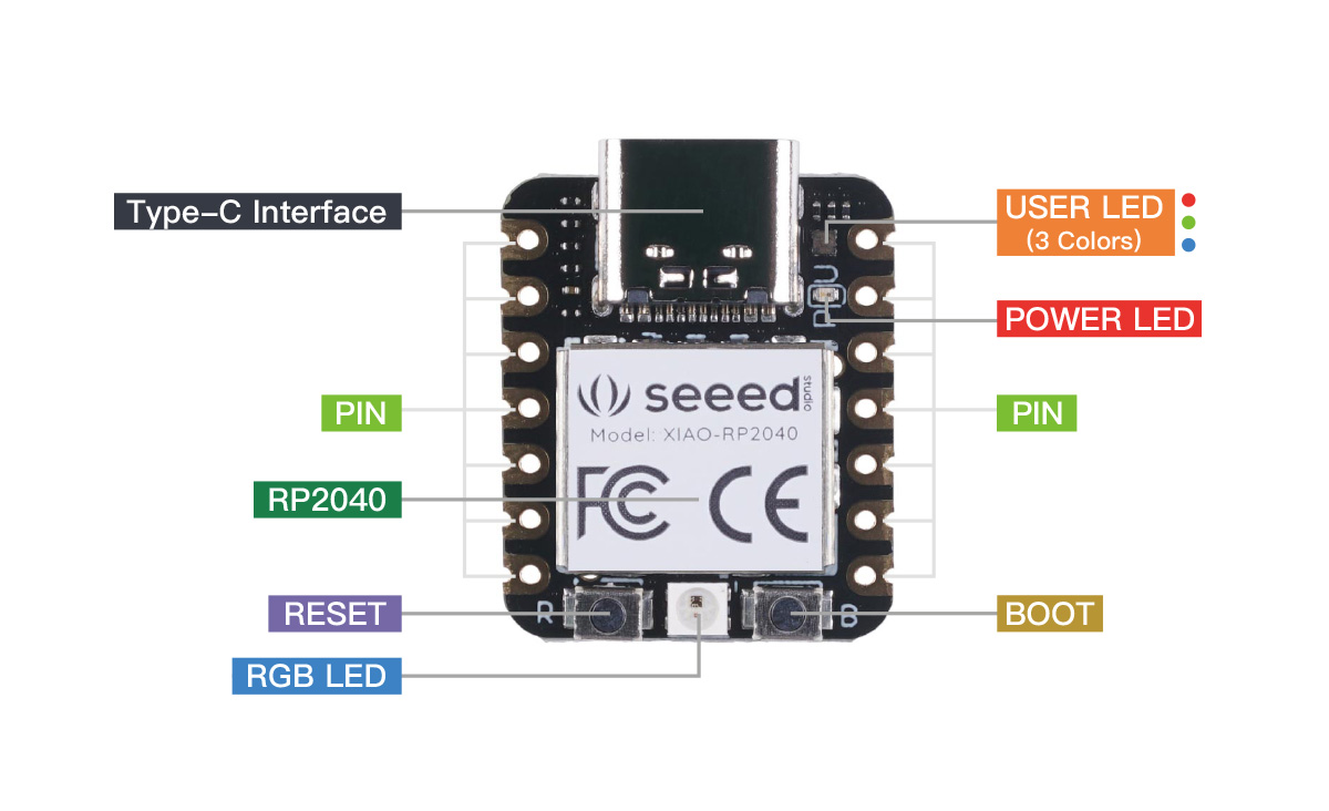
I have browsed through the Seed Studio XIAO RP2040 wiki and theRP2040 Datasheet by Raspberry (link) and here I include some of the most relevant features of this microcontroller
The Seeed Studio XIAO RP2040 is a small microcontroller board designed for embedded systems development. It is based on the dual-core ARM Cortex M0+ processor with a flexible clock speed that can run up to 133 MHz. The board also features 264KB of SRAM and 2MB of on-board Flash memory.

Here are some of the key capabilities of the XIAO RP2040:
- Processing Power: The dual-core processor allows for efficient multitasking and can handle complex computations, making it suitable for signal processing and video applications. The processor also has a hardware multiplier.
- Memory: With 264KB of SRAM and 2MB of Flash memory, the board has enough space to store and run substantial programs. The external flash memory is accessed via a QSPI interface, which allows the system to execute code directly from the external memory.
- Flexibility: The XIAO RP2040 is compatible with Micropython, Arduino, and CircuitPython, providing a range of options for software development.
- Small Form Factor: Its tiny size (21x17.8mm) makes it suitable for wearable devices and other small projects.
- Bootloader Mode: The XIAO RP2040 can enter bootloader mode, allowing for reprogramming of the chip. This is done by holding the "B" button and connecting the board to the computer.
- Reset Functionality : The board can be reset by pressing the "R" button
- GPIO Pins: The board has 14 GPIO pins including 11 digital, 4 analog, and 11 PWM pins, as well as I2C, UART, SPI, and SWD interfaces. The working voltage for general I/O pins is 3.3Vand exceeding that voltage may damage the chip.
- Power Supply: The device can be powered by 3.3V or 5V via VIN-PIN and 5V-PIN due to the built-in DC-DC converter circuit. However, when using battery power, Type-C connections are not supported due to potential safety risks.
The RP2040 features a dual-core Arm Cortex-M0+ processor clocked at 133MHz with 264KB internal SRAM and 2MB internal flash storage and can be programmed in both C/C++ and the beginner-friendly MicroPython.
|
Core Architecture |
32-bit ARM Cortex-M0+ |
|
Max Frequency |
133MHz |
|
Max Operating Temperature |
85°C |
|
Max Supply Voltage |
3.3 VDC |
|
Memory Size |
264KByte SRAM + Up to 16 Mbyte external Flash |
|
Memory Type |
Flash +SRAM |
|
Min Operating Temperature |
-20°C |
|
Min Supply Voltage |
2.5 V |
|
Number of ADC Channels |
5 |
|
Number of I/Os |
30 |
|
Number of PWM Channels |
16 |
|
Number of SPI Channels |
2 |
|
Number of UART Channels |
2 |
|
Number of USB Channels |
1 |
PROGRAMING THE XIAO RP2040
To program the Xiao RP2040 I am using the Arduino IDE (Integrated Development Environment).
My idea is to program the Xiao to blink two LEDs using buttons, and the LEDs should also be controllable from the serial monitor..
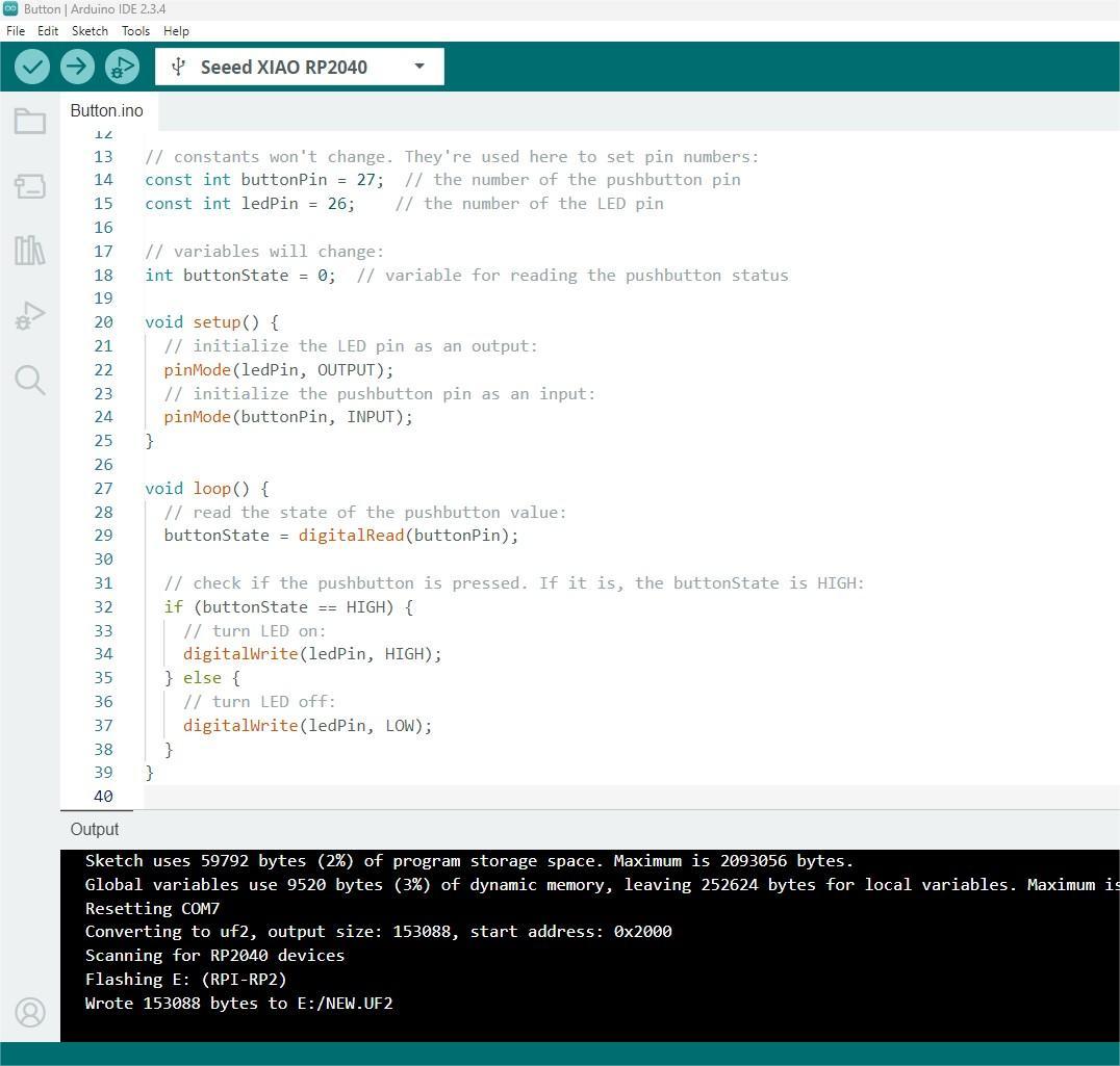
As I am not that familiar with coding I start using the built-in example "button" from Arduino IDE.
I am also using the Xiao in the development board sent to me by the team at Fab Lab León. This board is the Quentorres, created by Quentin Bolsée and redesigned by Adrián Torres.
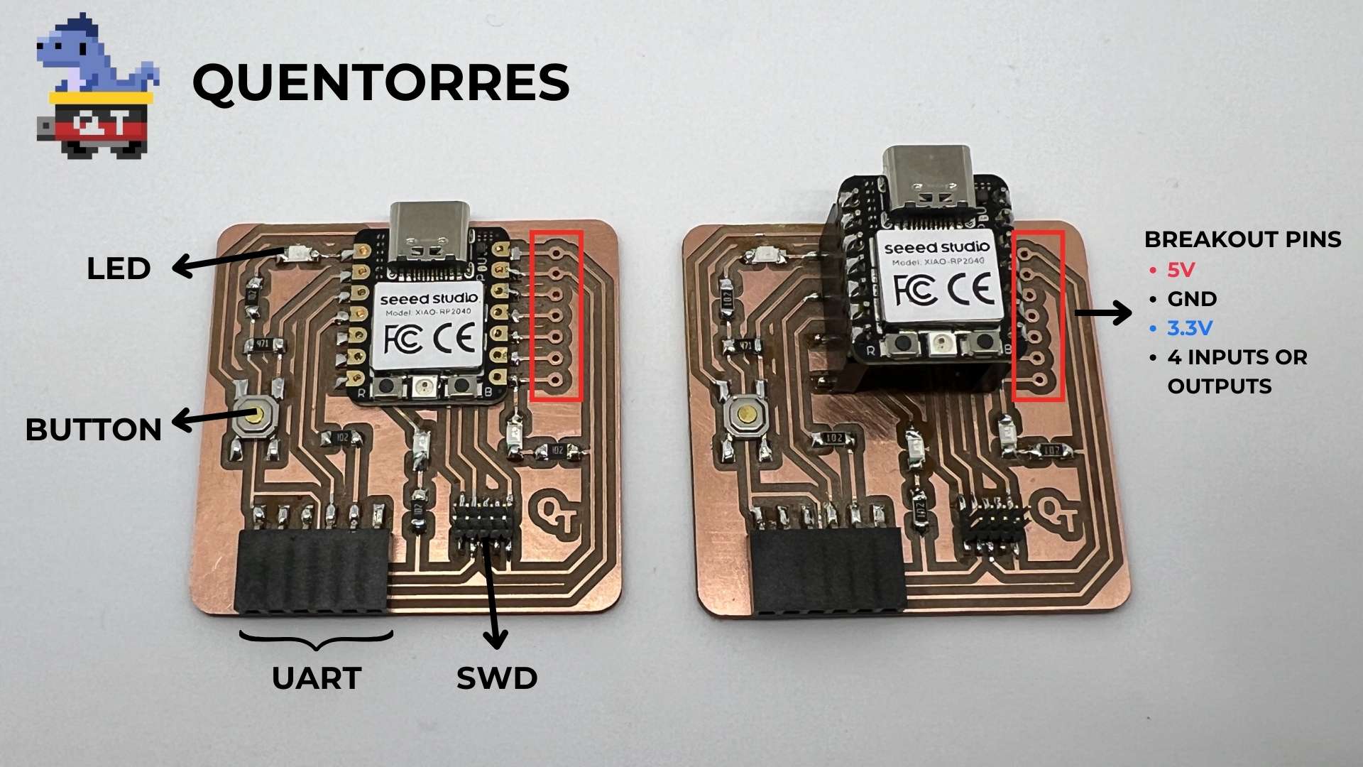
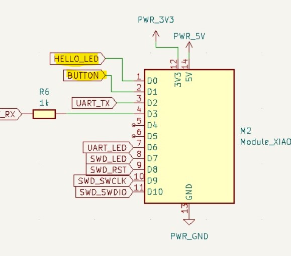
According to the information of the Quentorres the Hello_Led is connected to the D0 pin (or pin 26 of the RP2040) and the button to D1 (pin 27 of the RP2040).
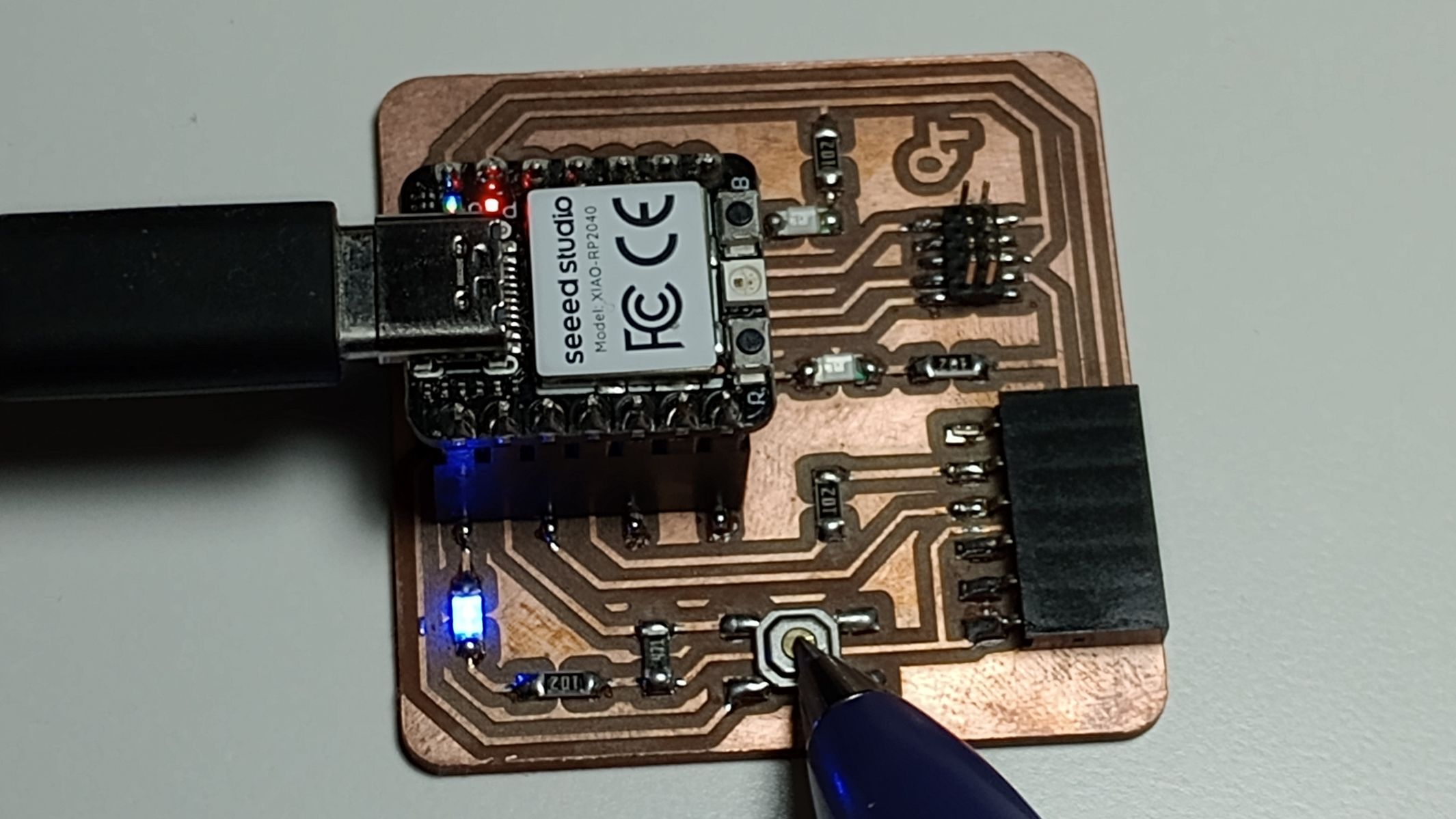
I change the pin numbers of the original code and I upload the code to the Xiao.
button_led_xiao.ino
/*
  Button_led_xiao_rp2040
*/
const int buttonPin = 27;  // the number of the pushbutton pin
const int ledPin = 26;    // the number of the LED pin

int buttonState = 0;  // variable for reading the pushbutton status

void setup() {
  // initialize the LED pin as an output:
  pinMode(ledPin, OUTPUT);
  // initialize the pushbutton pin as an input:
  pinMode(buttonPin, INPUT);
}

void loop() {
  // read the state of the pushbutton value:
  buttonState = digitalRead(buttonPin);

  // check if the pushbutton is pressed. If it is, the buttonState is HIGH:
  if (buttonState == HIGH) {
    // turn LED on:
    digitalWrite(ledPin, HIGH);
  } else {
    // turn LED off:
    digitalWrite(ledPin, LOW);
  }
}
I want to try something a bit more complex. My initial idea is to code and simulate the control of two LEDs using two buttons, which can also be controlled from the serial monitor.
I watched the "Hello Button Blink" example by Neil Gershenfeld, and I also looked at a video tutorial on how to control LEDs using the Serial Monitor.
I now have a good understanding of how to write the code. Since the QT development board doesn’t have two built-in buttons, I decide to use a breadboard to design and build the circuit.
I created an account on WOKWI, an online embedded systems simulator. I explored the available parts and believe I can design the circuit with basic components that I can later replicate with physical components I have on hand. Although there is no Xiao microcontroller available in Wokwi, I used the Raspberry Pi Pico, which has the same controller.
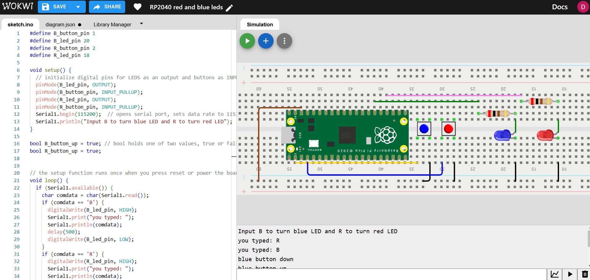
WOKWI simulation red and blue LEDs
After resolving some issues with the "if" statements and visualizing the output in the serial monitor, I managed to get the simulation running smoothly.
Now, when the red or blue buttons are pressed, the corresponding LEDs turn on, and the serial monitor displays the status of the buttons—whether they are pressed up or down.
Additionally, I can type "R" or "B" in the serial monitor to turn on the red or blue LEDs, respectively.
Now it’s time to test the code with a real circuit. I use a protoboard to make a similar circuit to the one in Wokwi, this time using the Xiao instead of the Raspberry Pico.
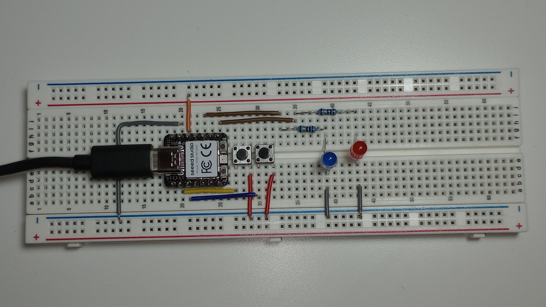
Next, I use a similar code in the Arduino IDE with the correct pins for the Xiao RP2040. I upload the code to the microcontroller, and as shown in the video, it works just like in the simulator.
red_blue_blink_led.ino
//
// Seeed XIAO RP2040 button, blink, echo hello-world
//
// based on code by Neil Gershenfeld
//
//#define allows the programmer to give a name to a constant value before the program is compiled
#define B_button_pin D1
#define B_led_pin D9
#define R_button_pin D2
#define R_led_pin D7

// the setup function runs once when you press reset or power the board
void setup() {
  // initialize digital pins for LEDS as an output and buttons as INPUTS
  pinMode(B_led_pin, OUTPUT);
  pinMode(B_button_pin,INPUT_PULLUP);
  pinMode(R_led_pin, OUTPUT);
  pinMode(R_button_pin,INPUT_PULLUP);
  Serial.begin(9600);  // opens serial port, sets data rate to 9600 bps
  //Serial.setTimeout(10); //sets the maximum milliseconds to wait for serial data
  Serial.println("Input B to turn blue LED and R to turn red LED");
}
  bool B_button_up =true; //bool holds one of two values, true or false
  bool R_button_up =true;

// the loop function runs over and over again forever
void loop() {
    if (Serial.available()) {
          char comdata = char(Serial.read());
      if (comdata == 'B') {
        digitalWrite(B_led_pin,HIGH);
        Serial.print("you typed:");
        Serial.println(comdata);
        delay(500);
        digitalWrite(B_led_pin,LOW);
      }
      else if (comdata == 'R') {
        digitalWrite(R_led_pin,HIGH);
        Serial.print("you typed:");
        Serial.println(comdata);
        delay(500);
        digitalWrite(R_led_pin,LOW);
      }
  }
    // Check Blue Button
  if ((digitalRead(B_button_pin) == LOW) && B_button_up) {
      digitalWrite(B_led_pin,HIGH);
      Serial.println("blue button down");
      B_button_up = false;
      }
  if ((digitalRead(B_button_pin) == HIGH) && !B_button_up) {
        digitalWrite(B_led_pin,LOW);
        Serial.println("blue button up");
        B_button_up = true;
       }

  // Check Red Button
  if ((digitalRead(R_button_pin) == LOW) && R_button_up) {
      digitalWrite(R_led_pin,HIGH);
      Serial.println("red button down");
      R_button_up = false;
      }
  if ((digitalRead(R_button_pin) == HIGH) && !R_button_up) {
        digitalWrite(R_led_pin,LOW);
        Serial.println("red button up");
        R_button_up = true;
       }
    delay(50);
   }
EMBEDDED PROGRAMMING: CONTRIBUTION TO FINAL PROJECT
As final task for this week I decided to create a very simple simulation of part of my final project, a dual-axis solar tracker.
Using this example in Wokwi and using a ESP32 developing board I simulated a servo that changes position depending on the readings of two Photoresistor (LDR) sensor modules.
USEFUL LINKS AND RESOURCES
- Arduino Core for Nordic Semiconductor nRF5 based boards link to Github with the core to program the Nordic Semiconductor nRF51 or nRF52 board using the Arduino IDE.
- BBC micro:bit MicroPython documentation
- Raspberry Pi RP2040: Features, Boards, Projects. Blog from Seed Studio about the features and boards of the rp2040 chip.
- Quentorres. swd+uart adapter+hello board - xiao rp2040. Github link to the Quentorres development board for the Xiao RP2040.
- RP2040 Datasheet Link to the microcontroller RP2040 documentation by Raspberry Pi.
- Controlling LEDs using Serial Monitor in Arduino - (Experiment #8 - Get Started with Arduino) Link to video showing how to control LEDs from the Arduino IDE Serial Monitor.
- https://academy.cba.mit.edu/classes/embedded_programming/RP2040/hello.button-blink.RP2040.mp4 Video by Neil Gershenfel showing the hello button blink from Arduino IDE and Thonny IDE.
- hello.button-blink.RP2040.1.ino code by Neil Gershenfel for Seeed XIAO RP2040 button, blink, echo hello-world
FILES
blinkdemo_microbit.ino: Download link
blink_microbit.py: Download link
LEDCFade_esp32.ino: Download link
Button_led_xiao.ino: Download link
red_blue_blink_led.ino: Download link
solar tracker test ESP32_1servo.zip (Wokwi): Download link
Top