Week 15. Interface and Application Programming
Table of Contents
- WEEKLY PLAN
- GROUP ASSIGNMENT: Exploring MIT APP for interface and application programming
- INDIVIDUAL ASSIGNMENT: Interfacing a light sensor matrix with ESP32
- USEFUL LINKS AND RESOURCES
- FILES
WEEKLY PLAN
Group assignment:
- Compare as many tool options as possible.
Individual assignment:
- Write an application for the embedded board that you made that interfaces a user with an input and/or output device(s).
GROUP ASSIGNMENT: Exploring MIT APP for interface and application programming
This is the link to the Fab Lab León Group Assignments page. Since I am completing the group assignment on my own I left the documentation on this page.
MIT APP INVENTOR FEATURES
For the group assignment I have decided to explore the use of App Inventor and see how it can be used to create an interface to control devices.
MIT App Inventor is a tool that enables you to build mobile apps. It is free and uses blocks that snap together for programming, so no traditional coding is required. This makes this tool suitable for beginners, educators and rapid prototyping.
These are the main features of the app:
- Drag-and-drop UI builder: Buttons, sliders, lists, canvases, charts, etc.
- Blocks-based programming: Logic, variables, procedures, events—easy to read and debug.
- Live testing: See changes instantly on your phone with the AI Companion
- Packaging & sharing: Build APKs (and AABs) for Android; iOS works via the companion with limited packaging options.
- Device access: Camera, audio, sensors (accelerometer, GPS), file storage, notifications.
- Connectivity: Bluetooth Classic & Bluetooth Low Energy (BLE), Wi-Fi (Web component/HTTP), WebSockets (via extensions), MQTT (via extensions).
- Data storage: TinyDB (on-device), TinyWebDB, Firebase, CloudDB.
- Media & graphics: Canvas drawing, image/sound/video playback, simple animations.
- Extensions: Add custom components (e.g., advanced BLE, MQTT, charts).
The app is web based that only requires signing in. The platform features two main sections:
- Designer: Here, you visually arrange the user interface by dragging and dropping components (like buttons, text labels, images, and sounds) onto the screen. You can also add new screens to your app and adjust the properties of the components.
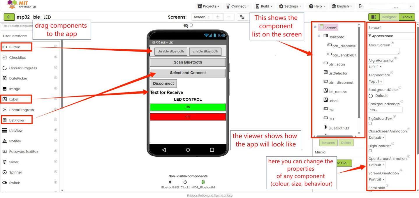
- Blocks Editor: This is where you program the app's functionality. Instead of text, you snap together graphical blocks that represent commands and actions, defining what happens when a user interacts with the app.
APP INVENTOR INTERFACE APPLICATION
I’m exploring the use of MIT App Inventor to control a microcontroller via Bluetooth Low Energy (BLE). I’m using:
- Microcontroller: Seeed Studio XIAO ESP32-C6
- Communication: BLE
- Interface: Android mobile app created with MIT App Inventor
- Application: Switch the built-in LED on and off
I started by creating the app layout and programming the behaviour of the UI elements. This app is based on the minimal BLE connection example by Juan Antonio Villalpando (http://kio4.com/arduino/160_Wemos_ESP32_BLE.htm)
Required extensions for BLE communication:
- KIO4_Bluetooth.aix (http://kio4.com/appinventor/aplicaciones/com.KIO4_Bluetooth.aix)
- BluetoothLE(MIT App Inventor) (https://iot.appinventor.mit.edu/iot/reference/bluetoothle)
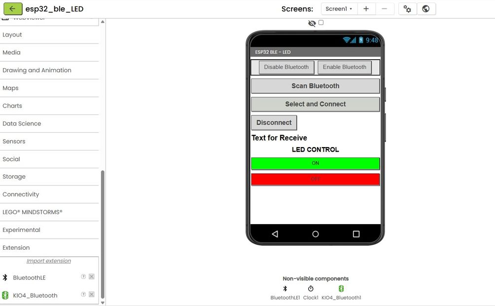
The layout of the app is shown below.
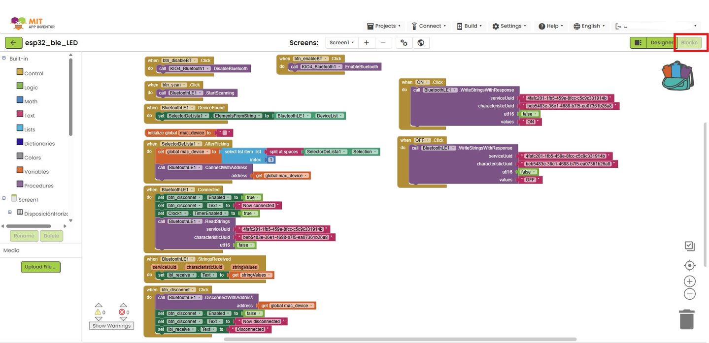
In the blocks editor I use the program for a BLE connection proposed by J A Villalpando and I add the blocks for the LED control. Here is an explanation of how the blocks work to established the BLE connections to a device
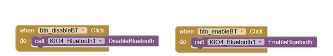
The blocks below enable and disable Bluetooth in the Android device. The extension KIO4_Bluetooth can be downloaded from this site: http://kio4.com/arduino/160_Wemos_ESP32_BLE.htm
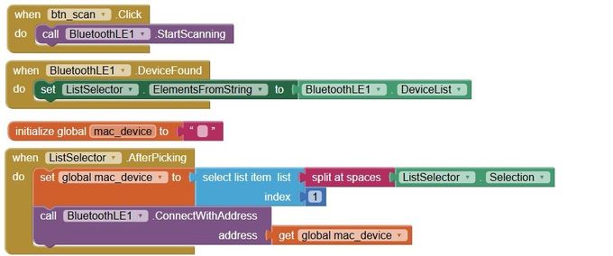
Next, when the Scan Bluetooth is pressed, the app will scan for for BLE devices. The devices found are listed and can be selected from a list picker. After pressing Scan Bluetooth, the app collects nearby BLE devices and fills the ListPicker with lines like: “device name” followed by its MAC address.
You tap Select and Connect and choose one line. That triggers ListPicker.AfterPicking.
In AfterPicking, the app takes the chosen text and extracts the MAC address (the hexadecimal string like e4:b3:23:b5:b0:82). The blocks do this by splitting the text and keeping the MAC part, then storing it in a variable called global mac_device.
The app then calls BluetoothLE1.ConnectWithAddress(mac_device). This tells the phone: “Connect to that exact device.”
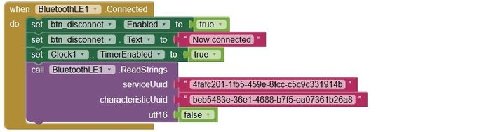
If the connection succeeds, the BluetoothLE1.Connected event changes the UI to “Now connected” and the app starts reading/writing to the ESP32. The Connected event also calls BluetoothLE1.ReadStrings (serviceUuid, characteristicUuid, utf16=false).
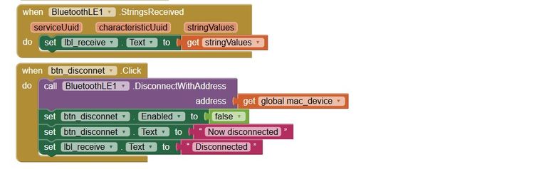
When the ESP32 sends anything back (e.g., “OK”, “ON”, sensor values), the block BluetoothLE1.StringsReceived is triggered.
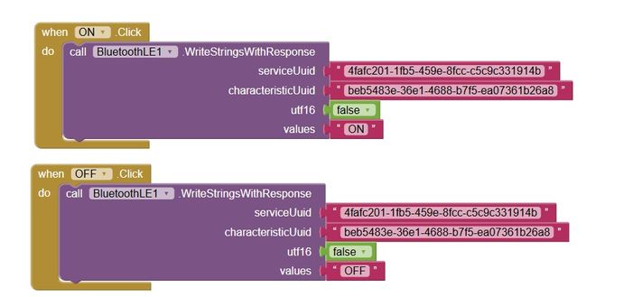
Send commands to toggle the LED: When you tap ON, the app calls BluetoothLE1.WriteStringsWithResponse with:
- serviceUuid = the custom service UUID
- characteristicUuid = the ESP32 Rx characteristic
- utf16 = false (so it sends standard UTF-8 text)
- values = "ON"
That writes the text "ON" into the ESP32’s Rx characteristic.
The ESP32 code reads the string and turns the built-in LED on.
The OFF button does the exact same write but with "OFF", so the ESP32 turns the LED off.
Next, I focus on the code for the ESP32 side. I start by using the code for the minimal connection by J.A. Villalpando that can be found here.
The code includes the ESP32 BLE libraries. It defines the built-in LED pin as 15 (XIAO ESP32-C6 user LED) which is active-LOW (so LOW turns it on and HIGH turns it off).
It also defines one BLE Service UUID and one Characteristic UUID. The phone must use these.
Under setup() the code:
- Sets the LED pin as output and starts OFF (HIGH).
- Initializes BLE with the device name "XIAO_C6_BLE_LED".
- Creates a BLE server, a service with SERVICE_UUID, and a characteristic with READ + WRITE properties.
- Attaches the write callback above and seeds the characteristic value with "Connected." (so a client read returns that string).
- Starts the service and starts advertising so the phone can discover and connect
xiao_BLE_LED.ino
#include <BLEDevice.h>
#include <BLEUtils.h>
#include <BLEServer.h>

#ifndef LED_BUILTIN
#define LED_BUILTIN 15   // XIAO ESP32-C6 user LED (active-LOW)
#endif

#define SERVICE_UUID        "4fafc201-1fb5-459e-8fcc-c5c9c331914b"
#define CHARACTERISTIC_UUID "beb5483e-36e1-4688-b7f5-ea07361b26a8"

// Handle incoming writes from the app
class LEDWriteCallback : public BLECharacteristicCallbacks {
  void onWrite(BLECharacteristic *ch) override {
    // Works whether getValue() is std::string or Arduino String
    String value = String(ch->getValue().c_str());
    if (value.length() == 0) return;

    value.trim();zz
    value.toUpperCase();

    if (value == "ON" || value == "1") {
      digitalWrite(LED_BUILTIN, LOW);   // active-LOW: LOW = ON
    } else if (value == "OFF" || value == "0") {
      digitalWrite(LED_BUILTIN, HIGH);  // HIGH = OFF
    }
  }
};

void setup() {
  pinMode(LED_BUILTIN, OUTPUT);
  digitalWrite(LED_BUILTIN, HIGH); // start OFF (active-LOW LED)

  BLEDevice::init("XIAO_C6_BLE_LED");
  BLEServer  *server  = BLEDevice::createServer();
  BLEService *service = server->createService(SERVICE_UUID);

  BLECharacteristic *ch = service->createCharacteristic(
    CHARACTERISTIC_UUID,
    BLECharacteristic::PROPERTY_READ | BLECharacteristic::PROPERTY_WRITE
  );
  ch->setCallbacks(new LEDWriteCallback());
  ch->setValue("Connected.");
  service->start();
  BLEAdvertising *adv = BLEDevice::getAdvertising();
  adv->start();
}
void loop() { /* nothing needed */ }
The video shows the process of using the MIT AI2 Companion app to scan a QR code so the app created is loaded into an Android device.Then I enable the Bluetooth in the phone, scan for devices and select the ESP32 from the list.
Once connect I can use the buttons to switch on and off the built-in LED on the XIAO ESP32-C6.
FILES
MIT App Inventor project: Android interface for ESP32 LED control via BLE: xiao_BLE_LED.aia
XIAO ESP32-C6 code: LED control via BLE : xiao_BLE_LED.ino
Top
INDIVIDUAL ASSIGNMENT: Interfacing a light sensor matrix with ESP32
For the individual assignment, I’m creating an interface to monitor light intensity from a sensor I designed in Assignment 9 and built for my final project, a dual-axis solar tracker.
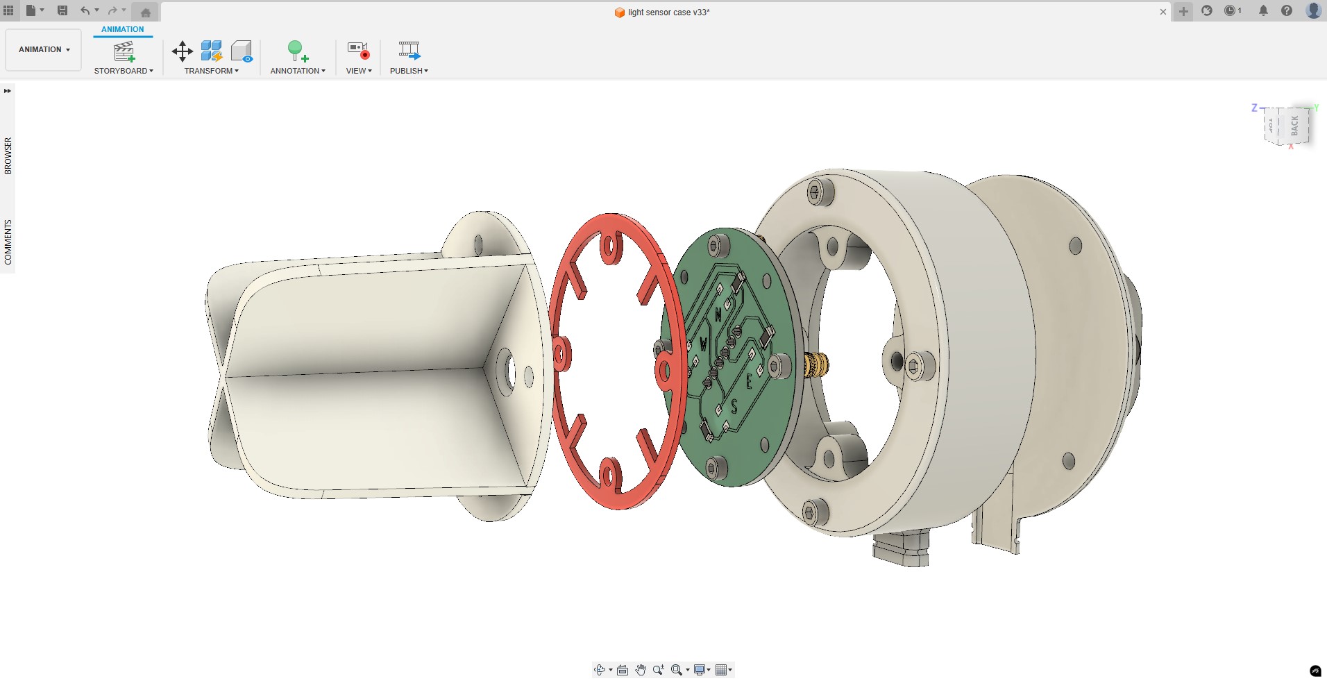
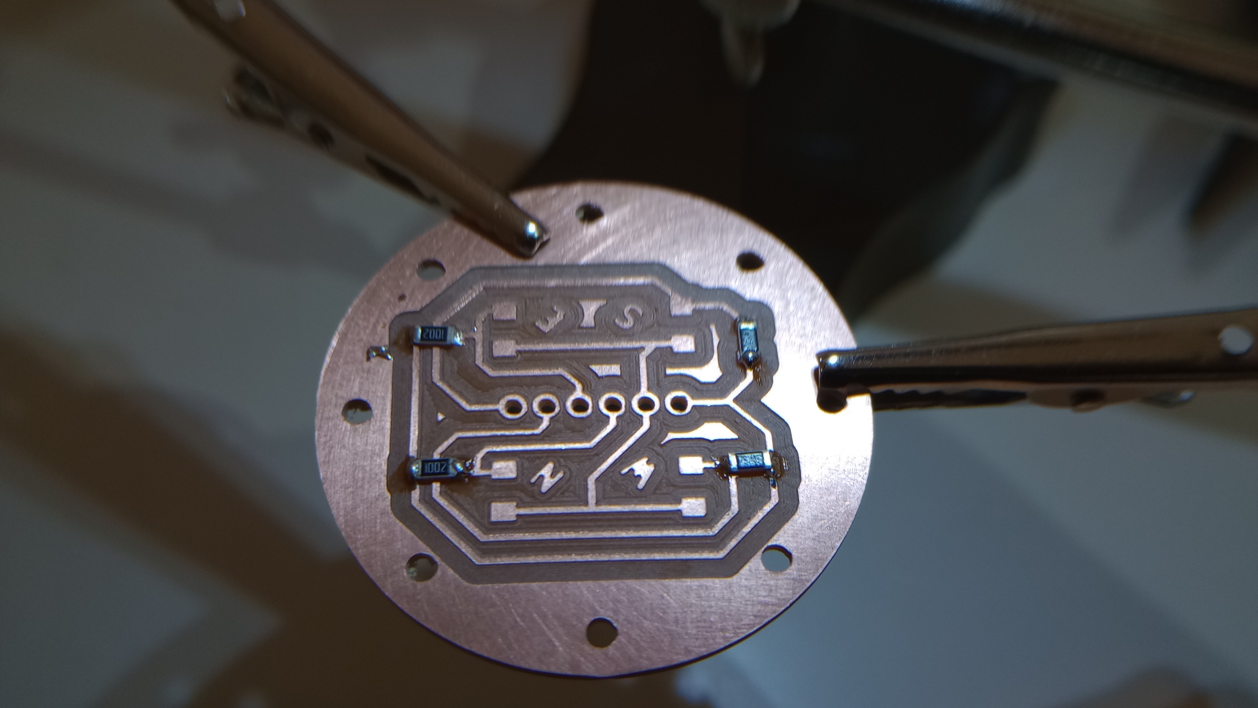
THE SENSOR
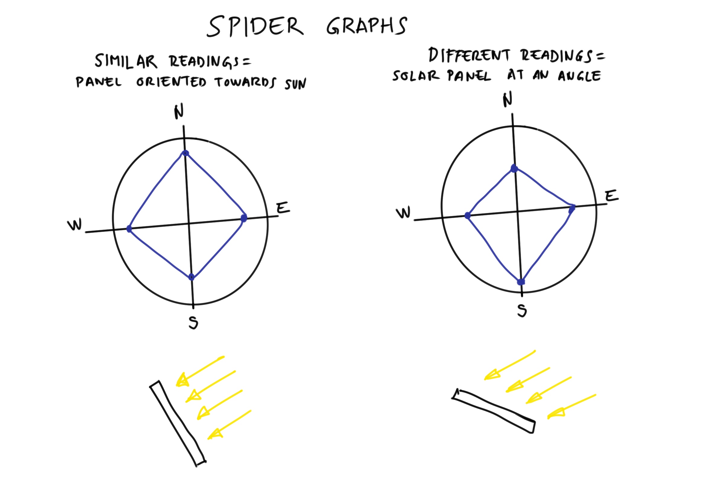
The sensor consists of four phototransistors arranged in a quadrant, corresponding to the north, south, east, and west directions. The PCB sensor is housed with screens that cast shade on each quadrant depending on orientation. Differences in light intensity caused by small changes in the incident angle are compared and used for solar tracking. I consider that a spider chart is a suitable way to visualize and compare the four readings.
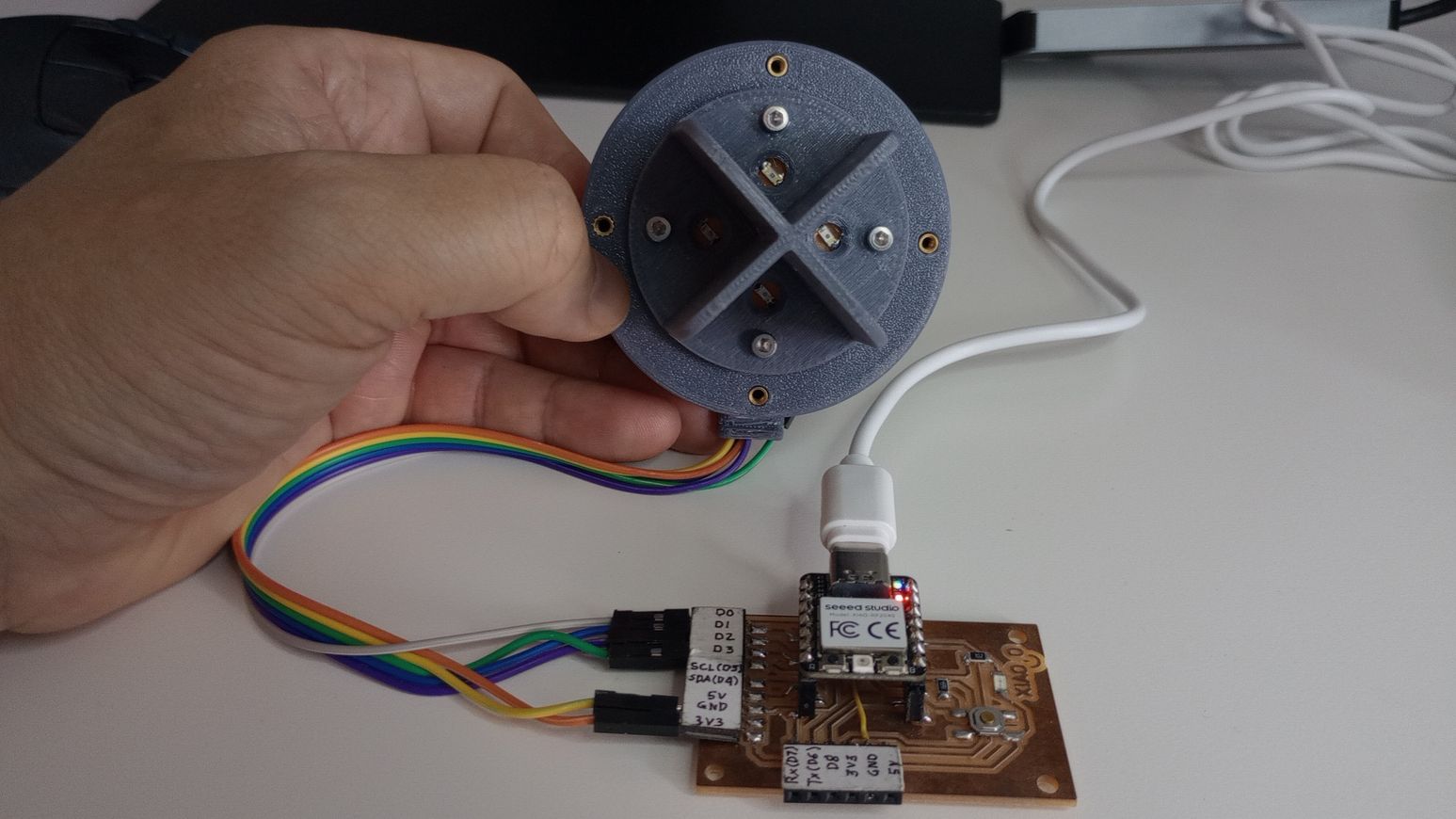
INTERFACING USING PROCESSING
I’m using a custom board built around a XIAO RP2040 for this task. The interface is written in Processing. This a lightweight, Java-based coding environment for building interactive dashboards, visualizers, and control panels for art, data, or hardware (e.g., Arduino/ESP32).
In Processing, the UI (buttons, sliders, plots) is rendered in draw(), and sensor data (e.g., from light sensors) is read over serial using the processing.serial library.
Because I couldn’t find a tutorial that matched my needs, I used ChatGPT to generate an initial sketch and explain how it works.
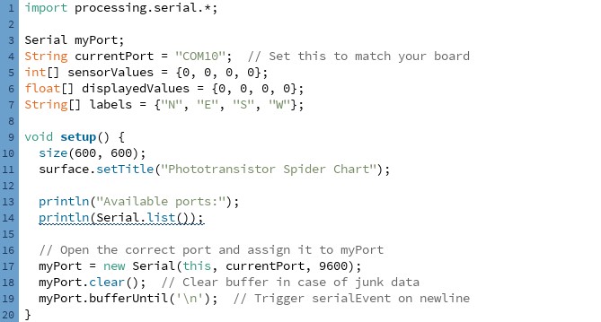
Globals
- currentPort: serial connection to the microcontroller.
- displayedValues: arrays holding the 4 readings you plot.
- labels: compass labels for the four axes.
setup()
- Creates a 600×600 window and sets the title.
- Prints available serial ports to the console
- Opens the serial port at 9600 baud, clears any data, and tells Processing to call serialEvent() whenever a newline \n arrives.
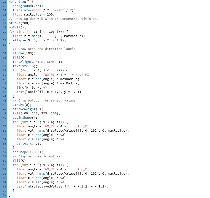
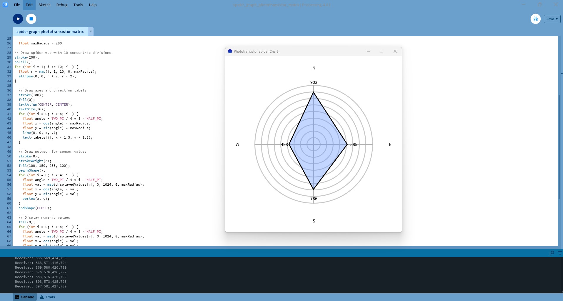
draw()
- Clears the screen and moves the origin to the center.
- Draws a “spider web”: 10 concentric circles up to maxRadius = 200.
- Draws 4 axes and places N/E/S/W at their ends.
The angle is calculated, so the first axis points up (North), then goes clockwise (E, S, W). - Plots the sensor polygon: each displayedValues[i] is mapped from 0..1024 to 0..maxRadius, converted to (x,y) via cos/sin, and connected as a filled, semi-transparent shape.
- Writes the numeric reading near each vertex.
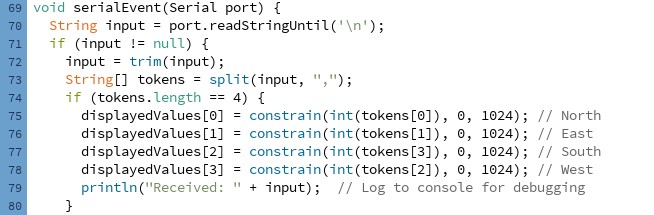
serialEvent()
- Waits for a line like a,b,c,d\n from the board, trims it, splits by commas, and—if there are 4 numbers—stores them (clamped 0–1024) in displayedValues.
- The assignments intentionally swap the last two tokens so directions match your physical layout: 0→N, 1→E, 3→S, 2→W.
PROGRAMMING THE MICROCONTROLLER
The microcontroller code (XIAO RP2040) samples four analog channels (D0–D3) where the phototransistors are connected, flips each reading so “more light” becomes a larger (or smaller) number using map(), then streams the four values as a comma-separated line (N,E,W,S) over USB every 500 ms.
/*
  AnalogReadSerial
  Reads an analog input on 4 pin, prints the result to the Serial Monitor.
  Graphical representation is available using Serial Plotter (Tools > Serial Plotter menu).
*/

// the setup routine runs once when you press reset:
void setup() {
  // initialize serial communication at 9600 bits per second:
  Serial.begin(9600);
}
// the loop routine runs over and over again forever:
 void loop() {
  int sensorValue_N = analogRead(D3);
  int sensorValue_E = analogRead(D2);
  int sensorValue_W = analogRead(D1);
  int sensorValue_S = analogRead(D0);

  sensorValue_N = map(sensorValue_N, 0, 1024, 1024, 0);
  sensorValue_E = map(sensorValue_E, 0, 1024, 1024, 0);
  sensorValue_W = map(sensorValue_W, 0, 1024, 1024, 0);
  sensorValue_S = map(sensorValue_S, 0, 1024, 1024, 0);

  // Send just numbers
  Serial.print(sensorValue_N); Serial.print(",");
  Serial.print(sensorValue_E); Serial.print(",");
  Serial.print(sensorValue_W); Serial.print(",");
  Serial.println(sensorValue_S);  // ends with newline

  delay(500);
}
After uploading the code to the microcontroller, I open Processing and run the sketch. It launches a window with a spider (radar) chart that updates in real time. The video shows that as I change the sensor’s orientation, the four phototransistor readings change, and the chart reflects those changes immediately.
USEFUL LINKS AND RESOURCES
FILES
Processing interface for light sensor matrix: spider_graph_phototransistor_matrix.pde
Light sensor matrix code for microcontroller: Light_Matrix_code.ino
Top