Week 05. 3D Scanning and Printing
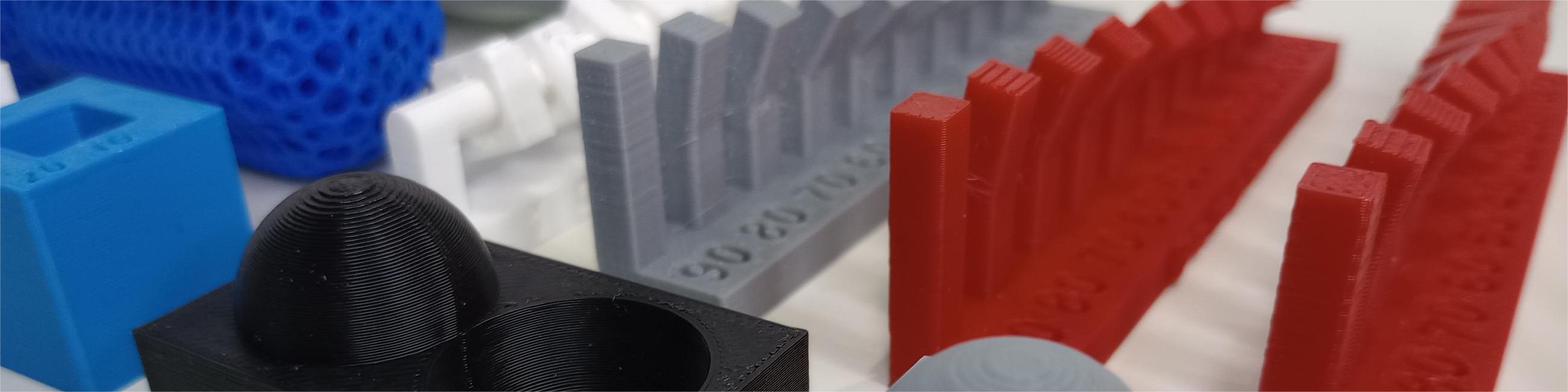
Table of Contents
- WEEKLY PLAN
- GROUP ASSIGNMENT:
- INDIVIDUAL ASSIGNMENT: 3D PRINTING AND SCANNING
- USEFUL LINKS AND RESOURCES
- FILES
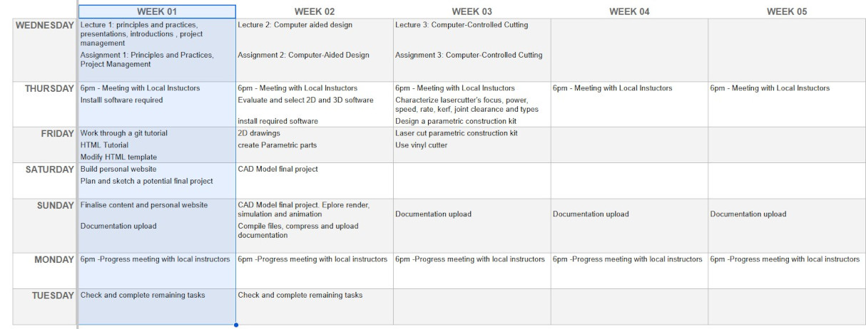
WEEKLY PLAN
Group assignment:
- Test the design rules for your 3D printers
- Document your work on the group work page and reflect on your individual page what you learned about characteristics of your printers
Individual assignment:
- Design and 3D print an object (small, few cm3, limited by printer time) that could not be easily made subtractively
- 3D scan an object (and optionally print it)
GROUP ASSIGNMENT:
This is the link to the Fab Lab León Group Assignments page. Since I am completing the group assignment on my own I left the documentation on this page.
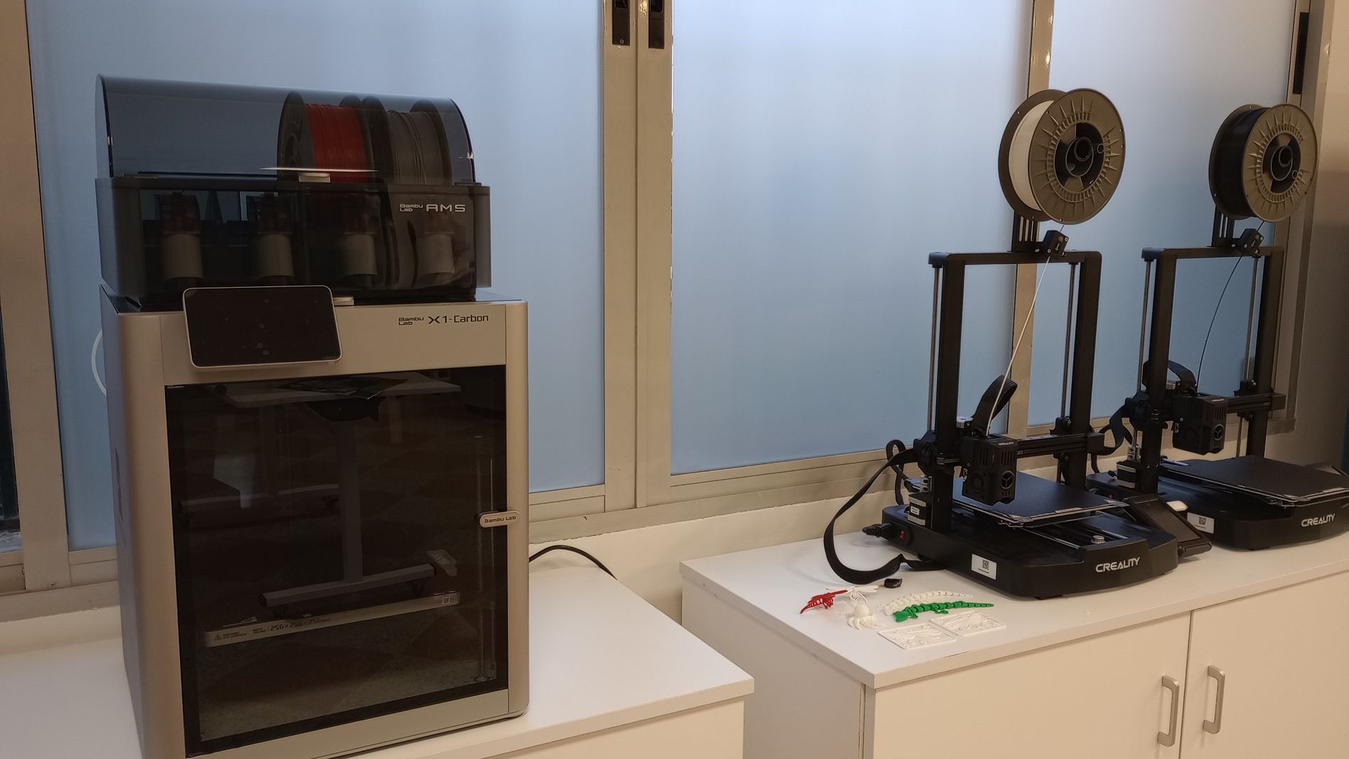
Bambu Lab X1 Carbon
Tech Specs
|
Build Volume (W×D×H) |
256 × 256 × 256 mm³ |
|
Nozzle |
0.4 mm Hardened Steel |
|
Max Hot End Temperature |
300 ℃ |
|
Filament Diameter |
1.75 mm |
|
Supported Filament |
PLA, PETG, TPU, ABS, ASA, PVA, PET, PA, PC, Carbon/ Glass Fiber Reinforced Polymer |
|
Max Build Plate Temperature |
110℃@220V |
|
Max Speed of Tool Head |
500 mm/s |
Slicer: Bambu Studio
The following tests were performed with thew following settings:
- Material: PLA
- Layer Height: 0.2mm
- Extrusion temp: 220 ℃
- Bed temp: 60 ℃
- Infill: 15%, grid
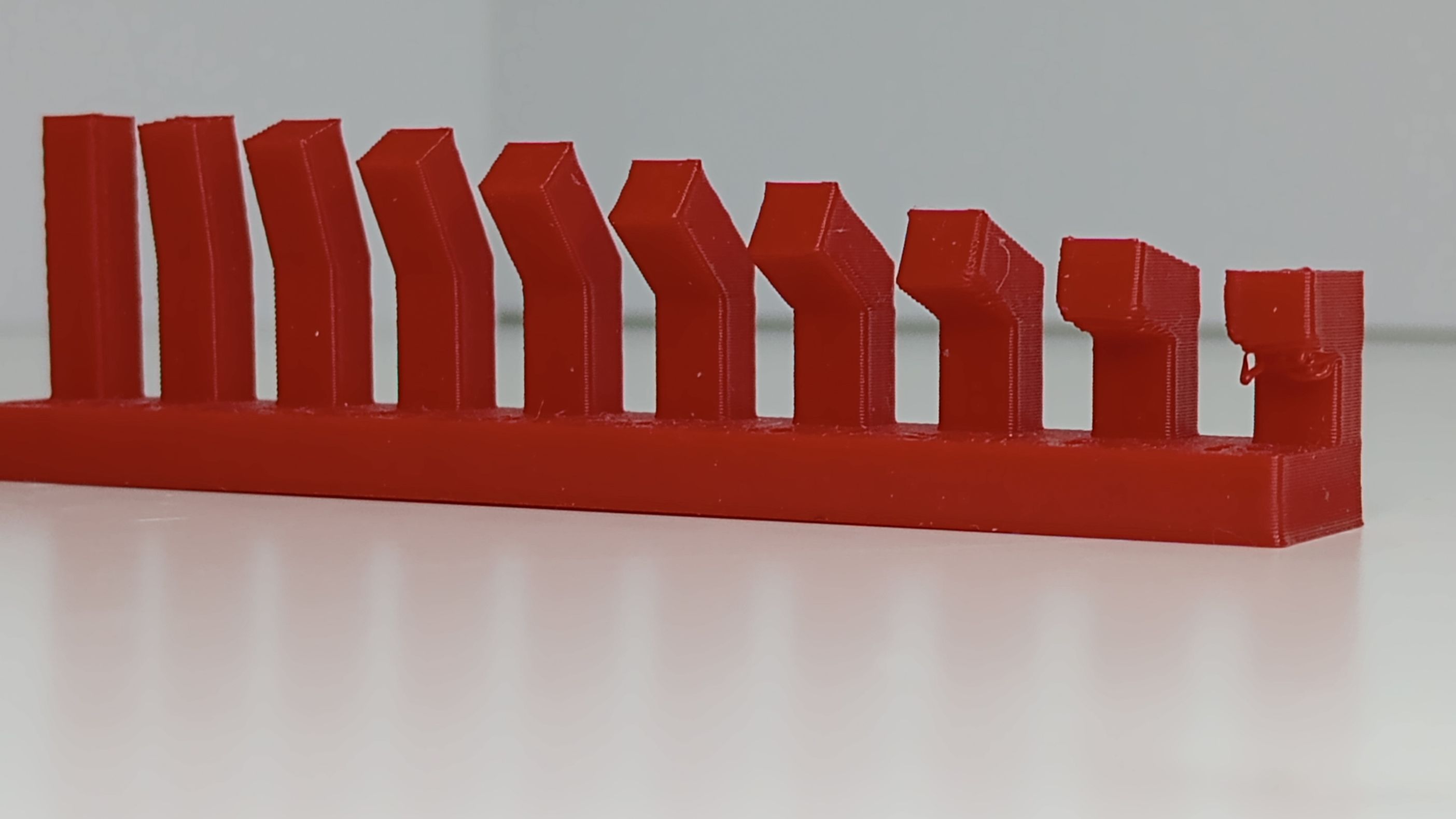
ANGLE TEST:
Printing time: 33 min
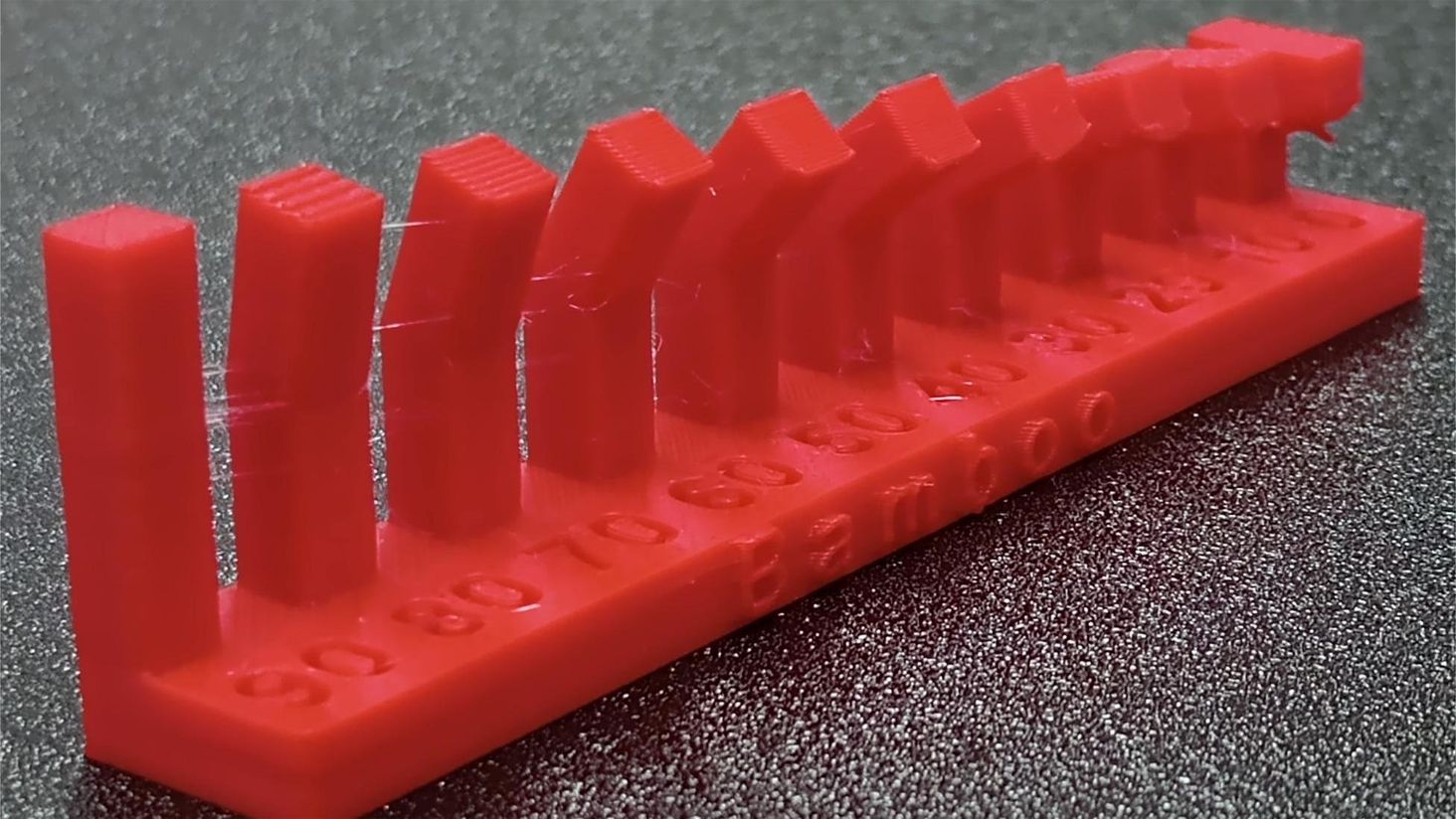
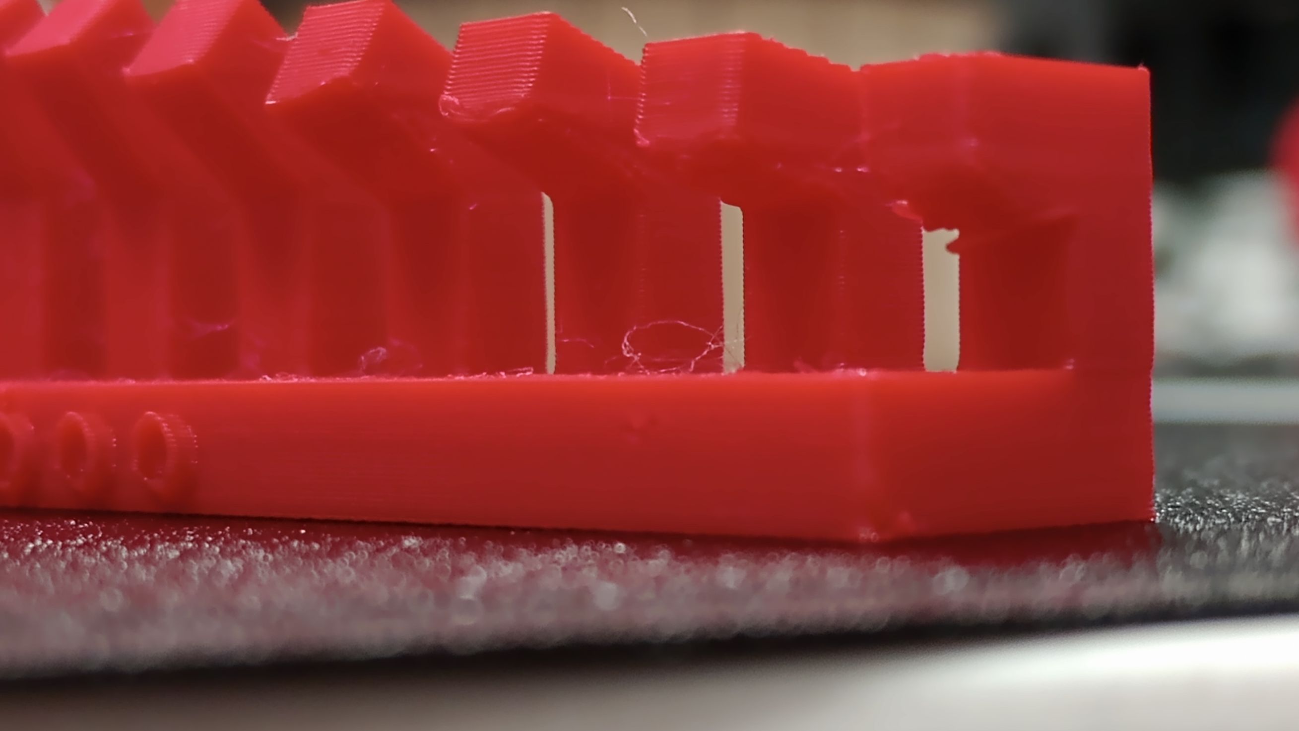
The printing result is quite good although some stringing between the overhangs can be seen, maybe due to too high temperature settings or incorrect retraction settings.
Although none of the overhangs collapsed, from the 30° angle I can observe deformation of the square section, and as it gets closer to the horizontal overhang (0° ) more deformation and sagging can be observed. When preparing objects to be printed with the Bambu X1 Carbon I would use supports for angles lower than 30°.
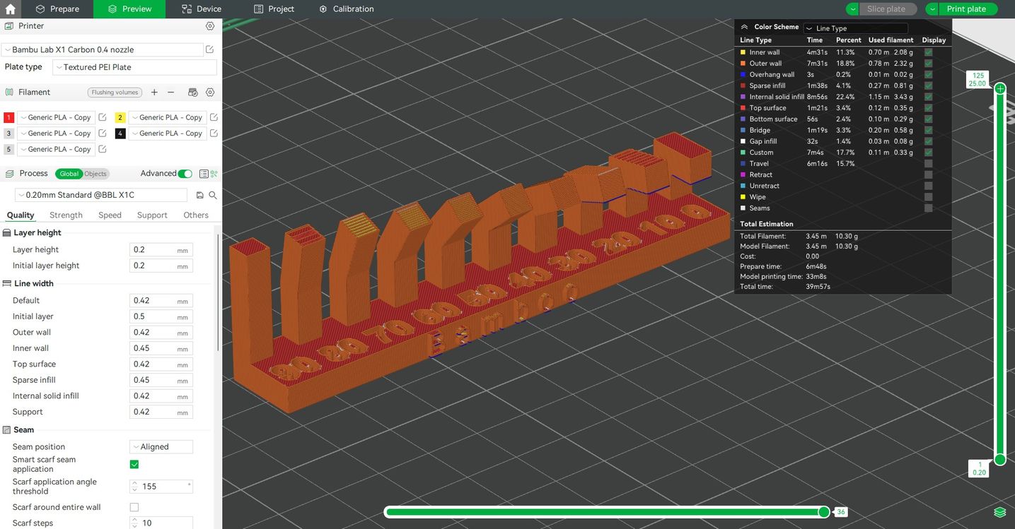
CLEARANCE TEST:
Printing time: 36 min
This test helps to determine the clearance required to achieve different fits between parts. With a clearance of 0.2mm is a tight fit that can be moved so it could be useful to lock some parts in place. The piece with 0.1mm clearance is welded to the axis.
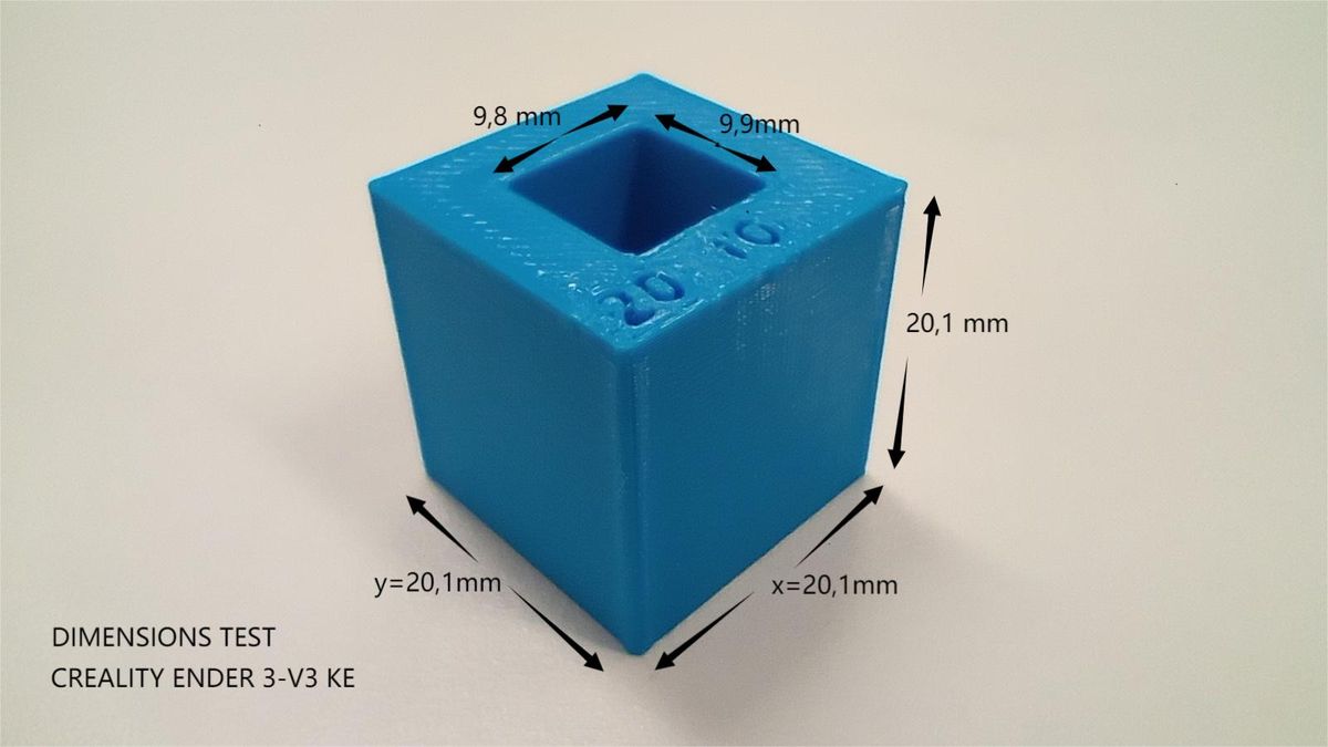
DIMENSION TEST:
Printing time: 9 min
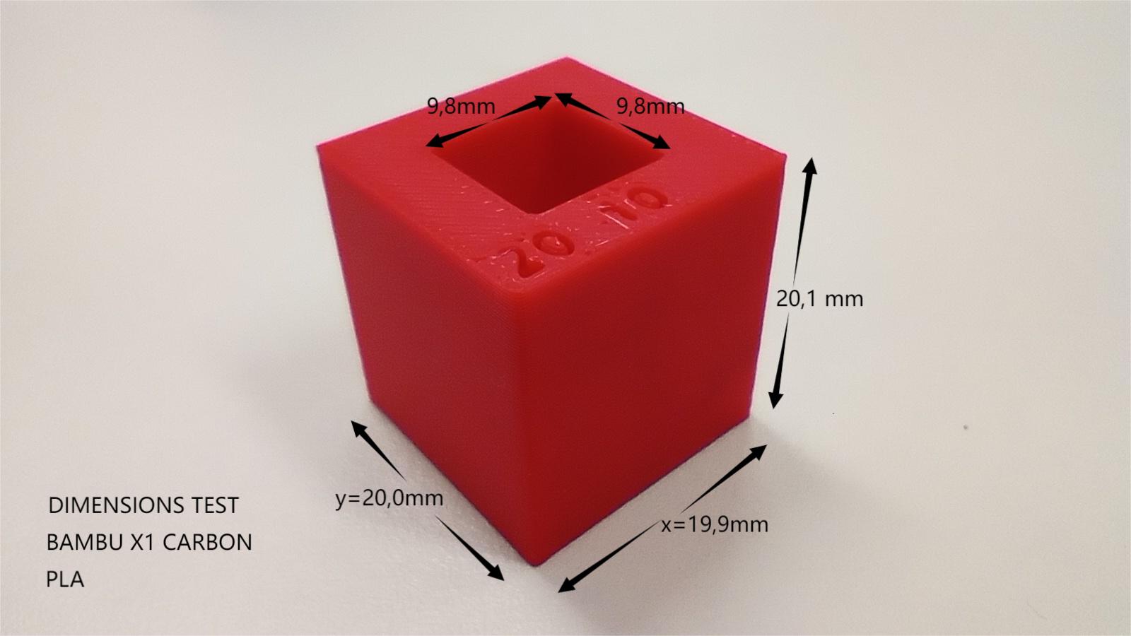
This test helps to determine the dimensional accuracy of the printed parts and to calibrate the machine. The image shows the real measurements of a 20x20x20mm cube with a 10x10mm hole.
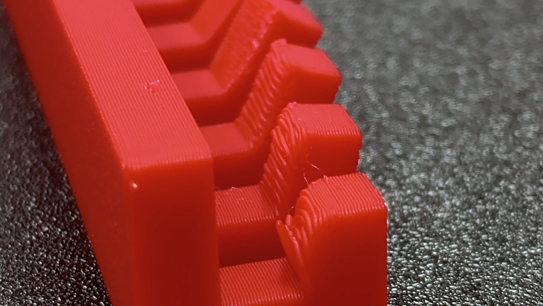
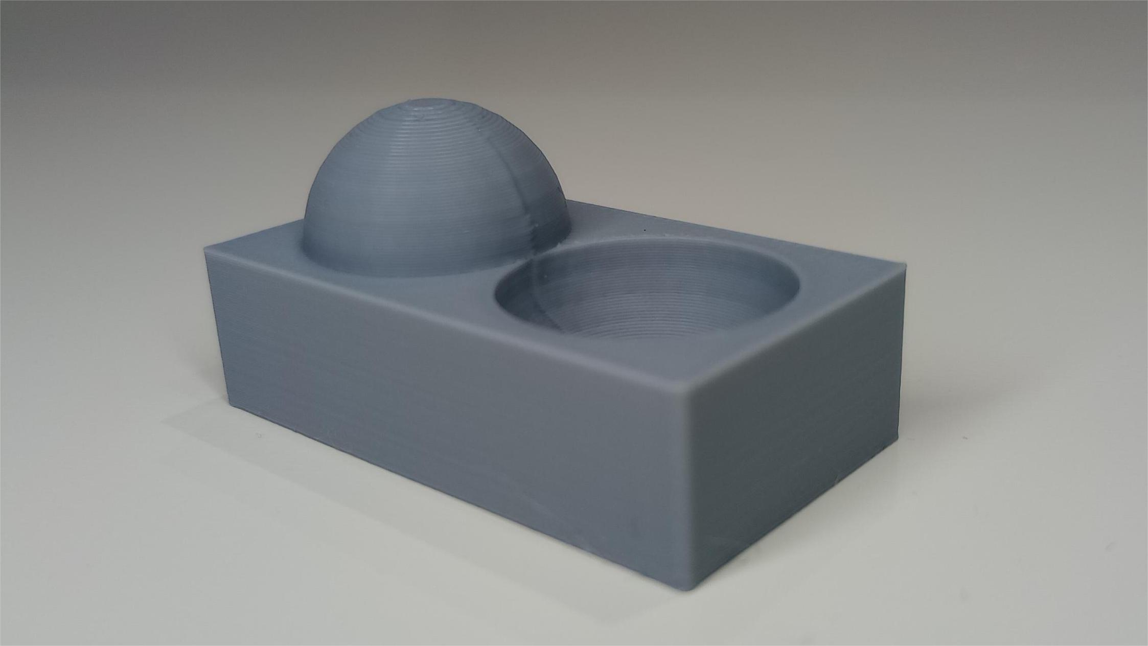
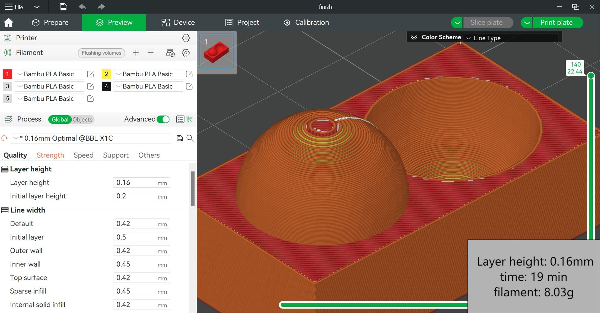
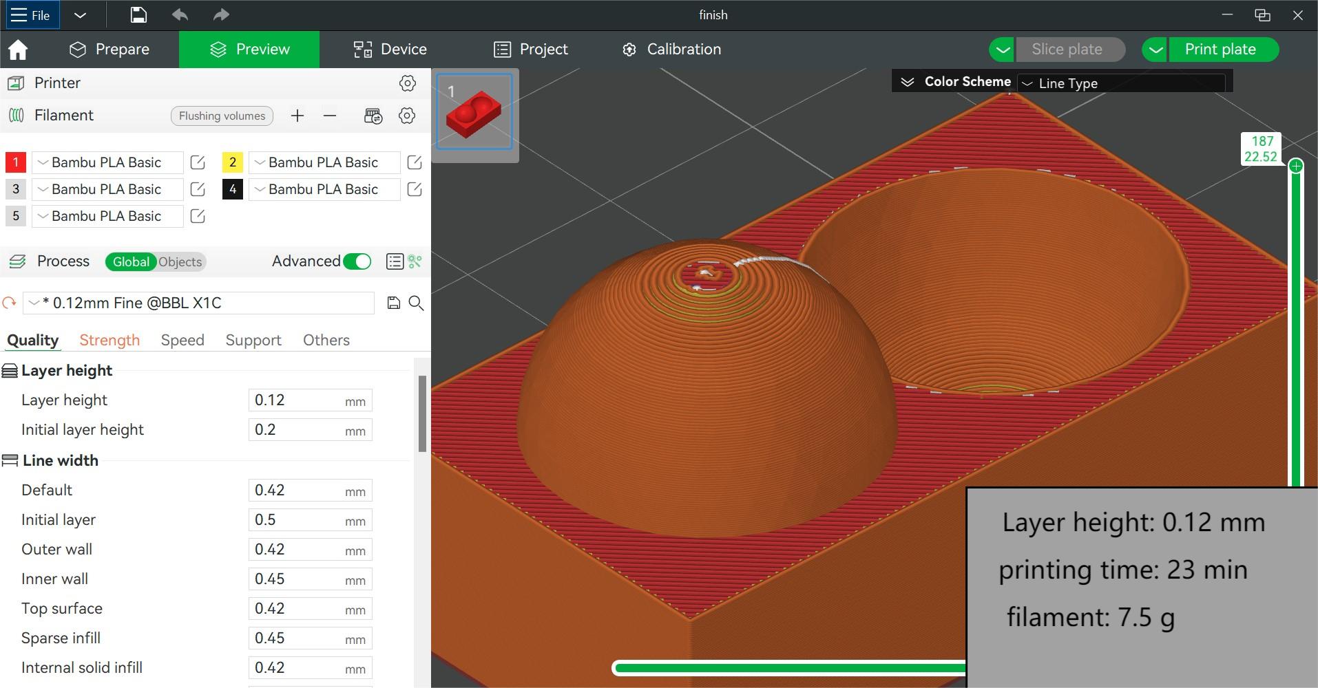
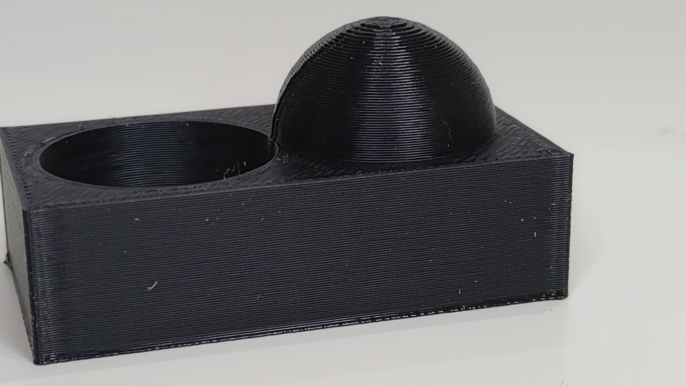
FINISH TEST:
Printing time: 15 min
This is a useful test to determine the finish quality of the printed object depending on the layer height. An standard 0.2mm layer height provides good finish although the layer pattern becomes noticeable when printing round shapes. Lower layer heights (0.16mm, 0.12 or 0.08 mm) are possible and will provide more resolution but will take longer and use more filament.
CREALITY ENDER 3-V3 KE
|
Build Volume (W×D×H) |
220 × 220 × 240 mm³ |
|
Nozzle |
0.4 mm Hardened Steel |
|
Max Hot End Temperature |
300 ℃ |
|
Filament Diameter |
1.75 mm |
|
Supported Filament |
PLA, PETG, TPU, ABS, ASA |
|
Max Build Plate Temperature |
110℃ |
|
Printing speed |
300 mm/s |
Slicer: Creality Print 5.1
ANGLE TEST:
Printing time: 30 min
CLEARANCE TEST:
Printing time: 45 min
DIMENSION TEST:
Printing time: 9 min
FINISH TEST:
Printing time: 17 min
Top
INDIVIDUAL ASSIGNMENT: 3D PRINTING AND SCANNING
Design and 3D print of an object.
For the design and 3D printing of a small object that cannot be created using subtractive methods, I have decided to explore the use of 3D lattice structures. According to this article by G. Shields on All3DP, "lattices can make parts lighter and stronger, absorb impact more efficiently, and be better customized to their end use." In fact, infills in 3D printed parts are examples of latticing.
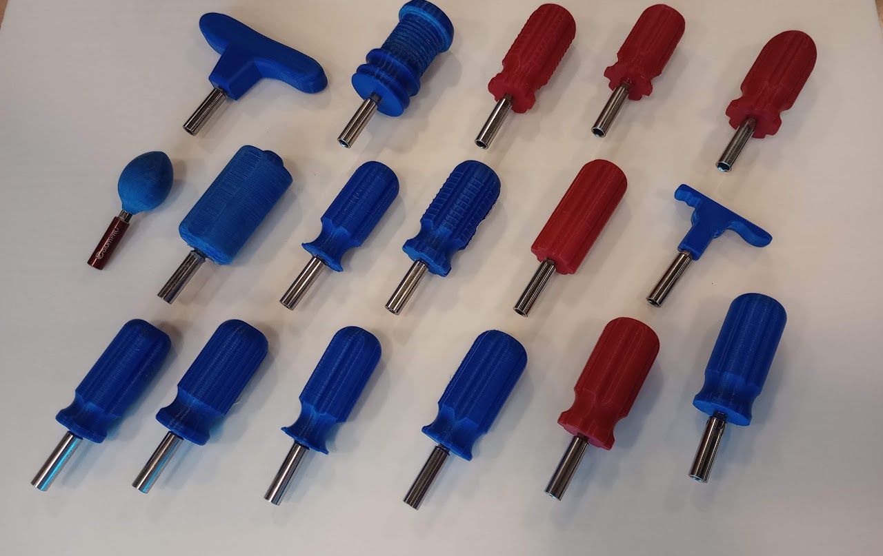
As a starting point, I am using a design that I created as part of a teaching project aimed at introducing concepts such as ergonomics, anthropometrics, prototyping, and 3D printing to secondary students. The project involves designing and manufacturing the handle of a compact screwdriver with a magnetic bit holder.
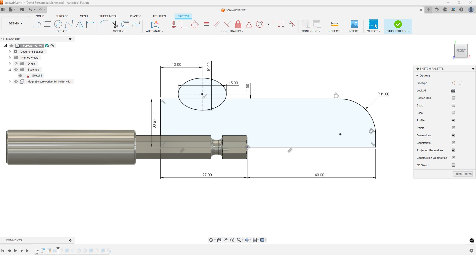
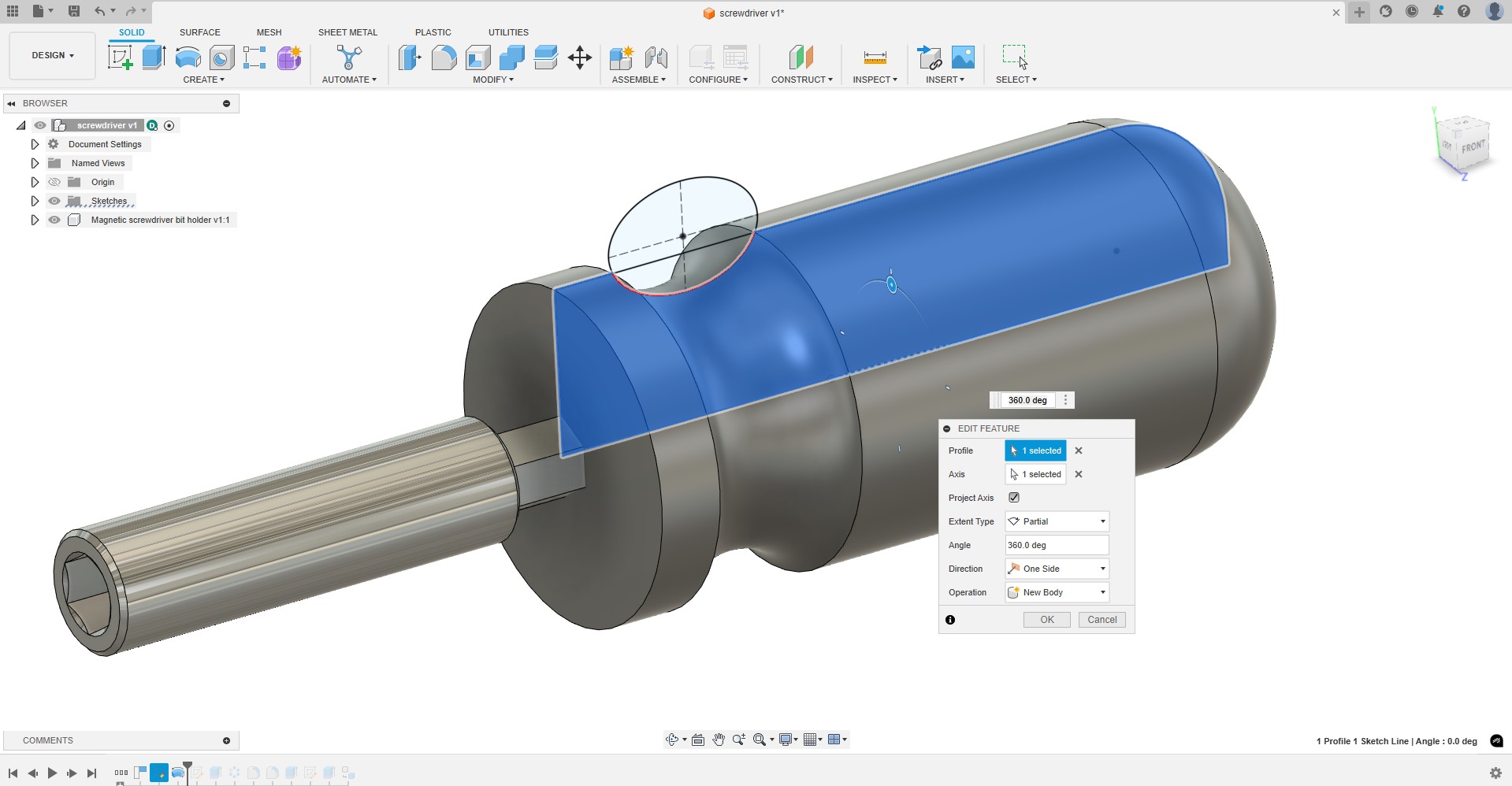
In the following steps I outline the design process for a simple, compact screwdriver using Autodesk Fusion. I begin by sketching the profile of the handle and then use the Revolve feature to create the solid.
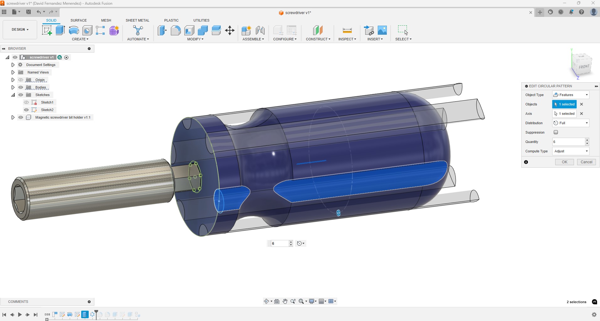
I create a groove along the handle, which I then replicate around 6 times using the Circular Pattern feature.
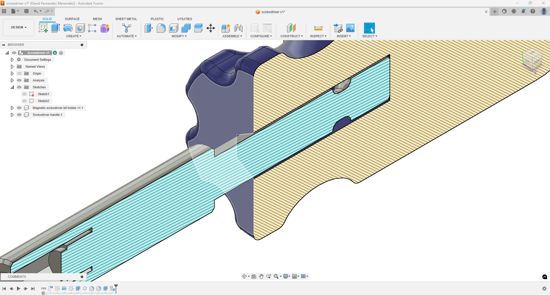
I create a hexagonal hole in the handle to insert the magnetic bit holder. I left a gap of 0.25 mm. While this gap is too large for a press-fit, I plan to use epoxy glue, so I've allowed enough space for the glue to flow out of the gap. I also added fillets to round off any sharp edges.
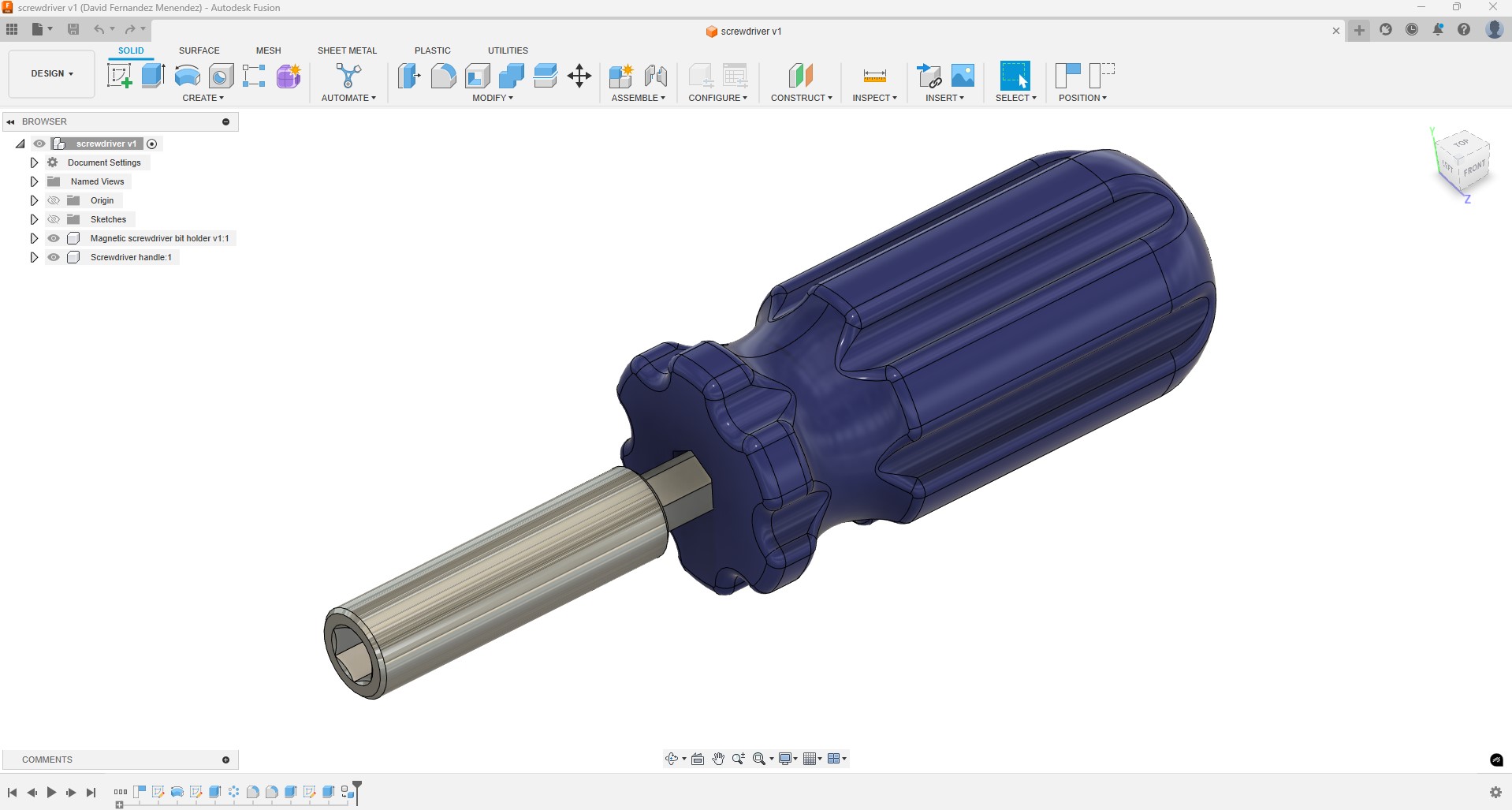
This design, as it is, can be 3D printed, but it can also be manufactured through subtractive methods or injection molding.
I want to use this design as the base to create a 3D lattice structure for the handle. I noticed that there is a Fusion Design Extension called “Volumetric Lattice” so I decide to try it.
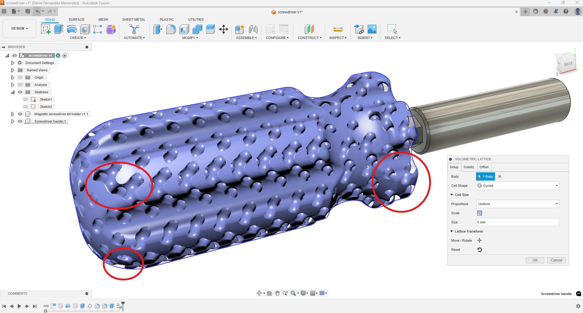
I experimented with various cell shapes and sizes, but I am not satisfied with the results, particularly because the lattice does not conform to the exterior surface of the handle. This results in sharp edges and areas that are thin and weak.
To resolve this issue, I decided to explore other tools for generating 3D lattices and found Meshmixer, a 3D modeling software that allows you to modify 3D models, edit meshes, sculpt, and prepare models for 3D printing.
I exported the handle as an .stl file and imported it into Meshmixer. To transform this design into a 3D lattice, I followed the steps outlined in this video tutorial (link).
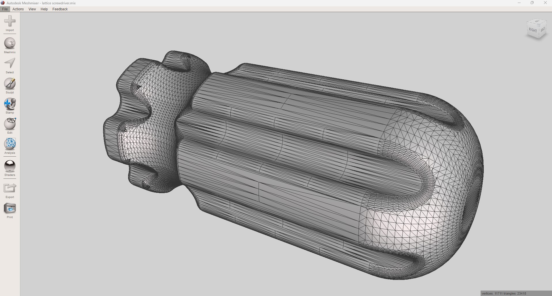
Since the lattice structure relies on the triangular mesh, it is essential to remesh the original design, as the current mesh is not suitable.
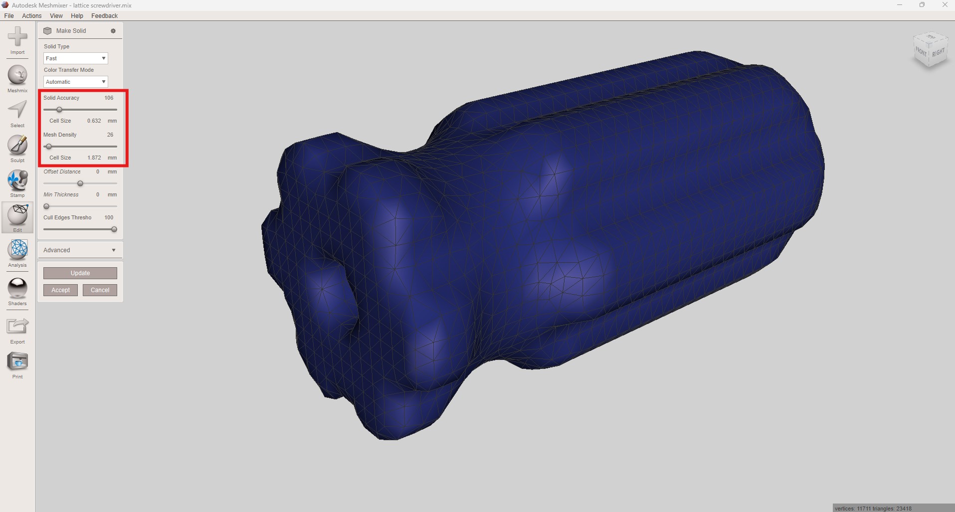
In the Edit menu, Make Solid, I can adjust the mesh density and solid accuracy. This allows for a more uniform mesh consisting of fewer, larger triangles while maintaining the shape of the solid as close to the original as possible.
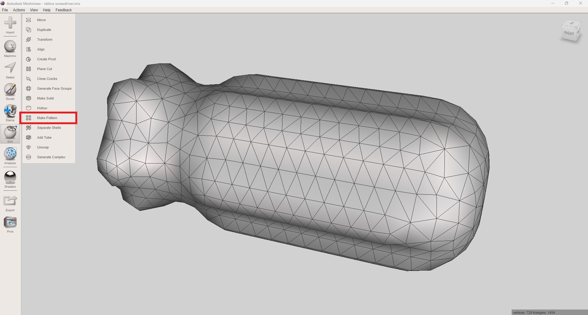
With the new mesh I go to Edit>Make Pattern. Here I choose the pattern type, element diameter and grid size until I am happy with the result.
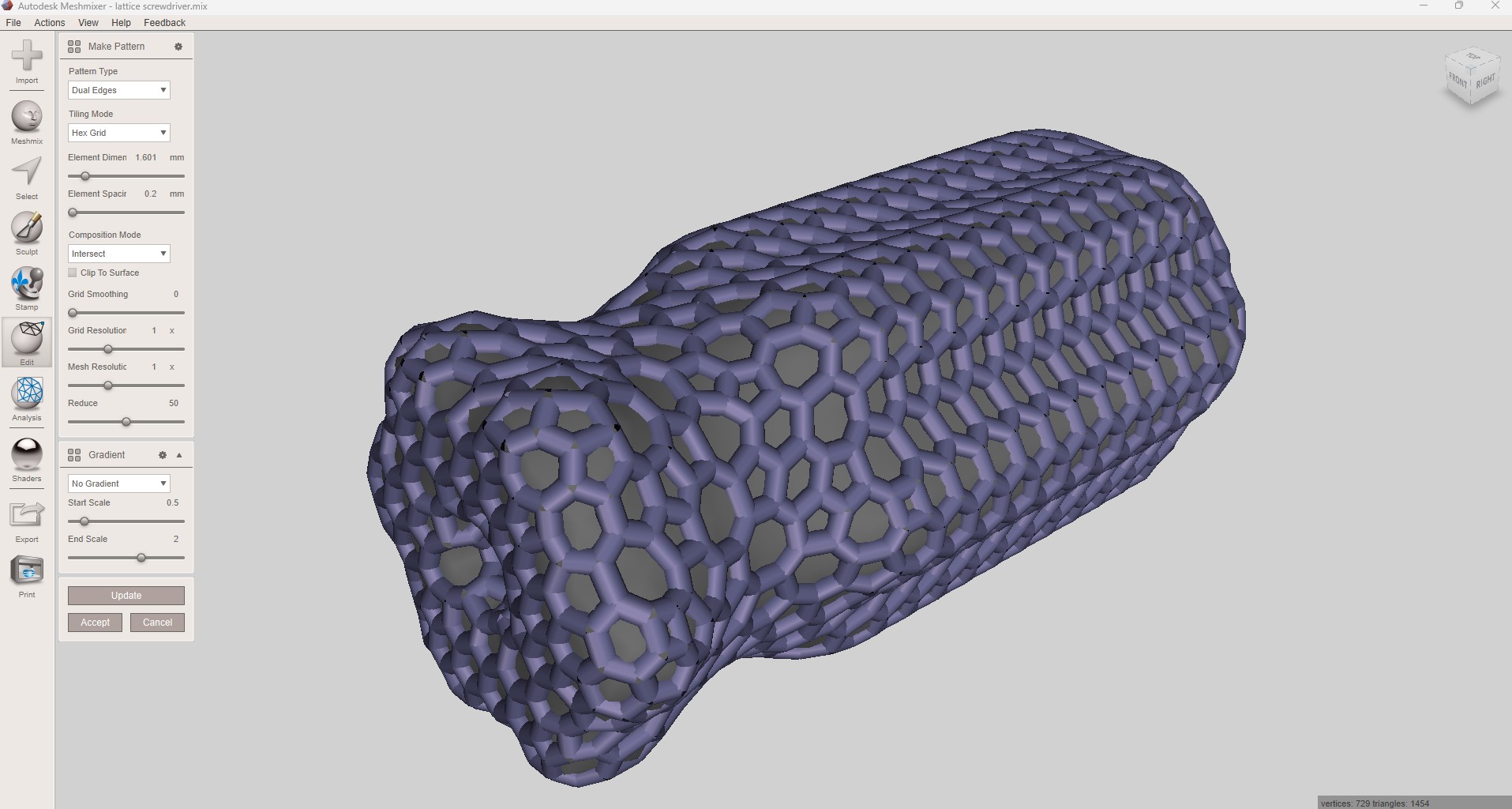
After the processing, a 3D lattice structure is generated, filling the inside of the handle.
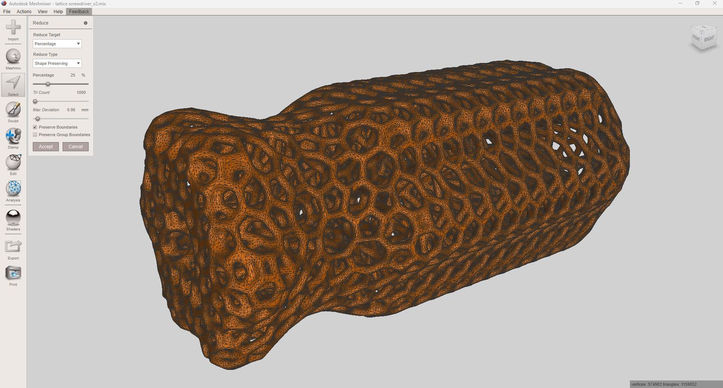
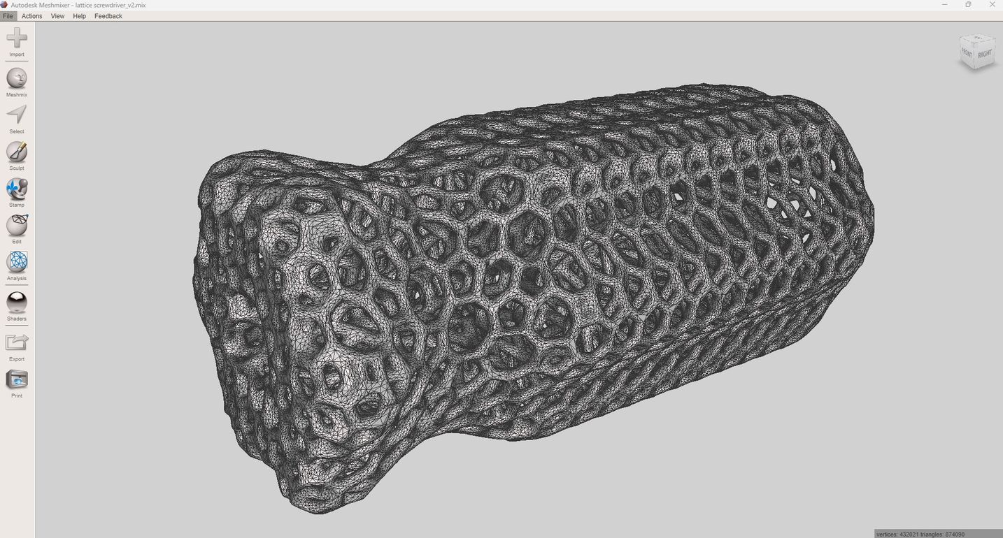
The mesh is now very dense (more than a million triangles) so I use the “reduce” command to reduce the number of triangles.
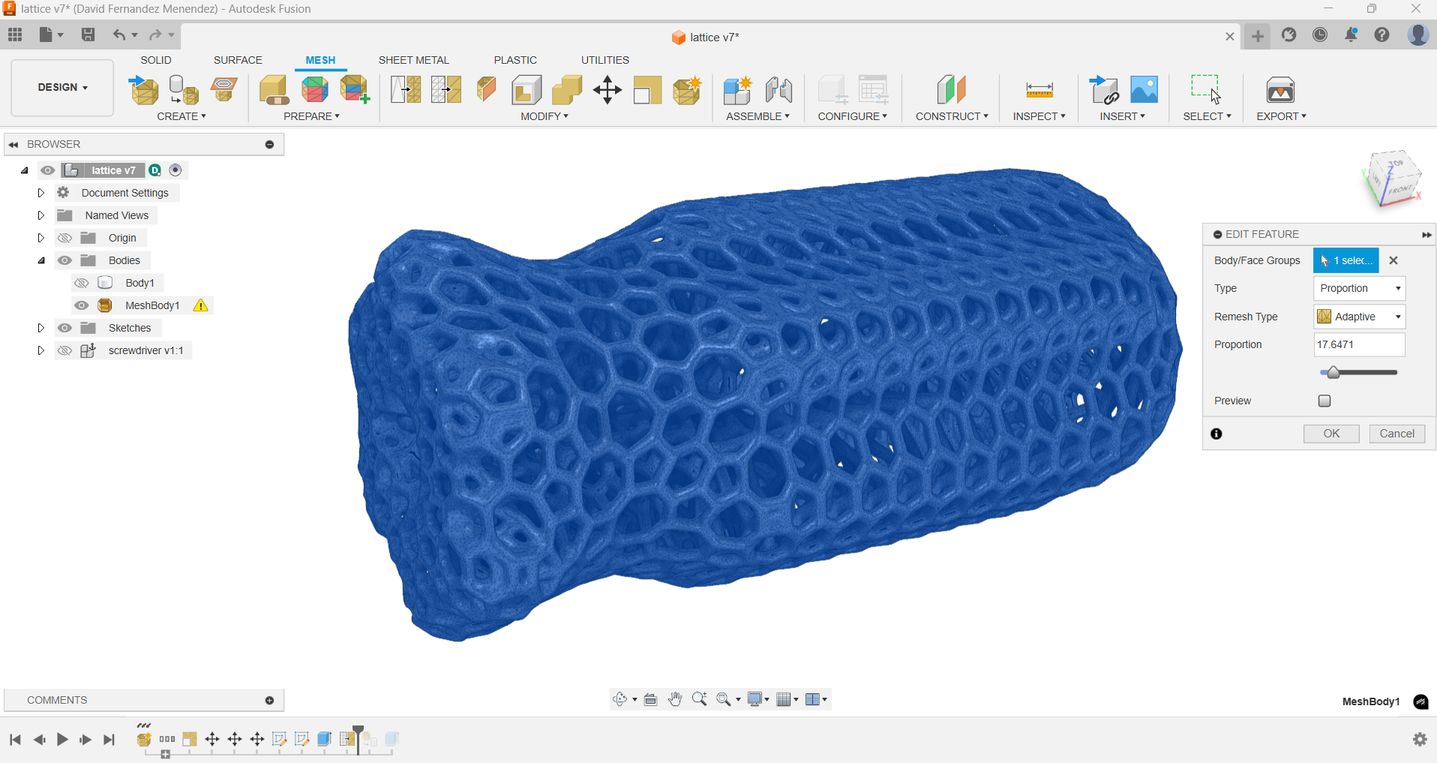
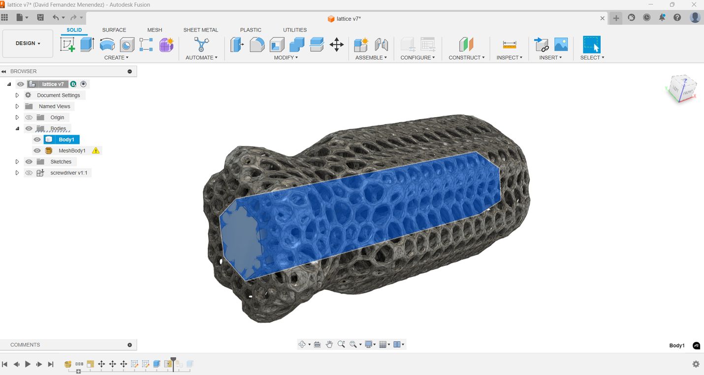
Since the shape of the hole for the magnetic bit holder has changed during the latticing process, I export the solid as an .stl file and import it into Fusion to fix this area. I realize that the design is too heavy, which makes it difficult to work in Fusion. In the Mesh environment, there is an option to reduce the mesh and convert it into a solid.
I add a central hexagonal prism to reinforce the whole centre of the handle and to cut the hole to insert the magnetic bit holder.
The handle is now ready to be exported again, this time for slicing and preparing for 3D printing.
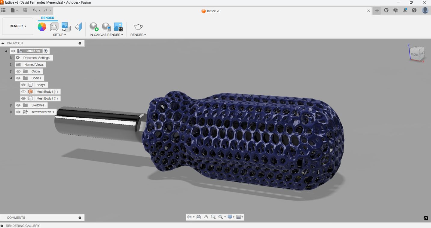
The handle is now ready to be exported again, this time for slicing and preparing for 3D printing.
Top
Slicing and printing
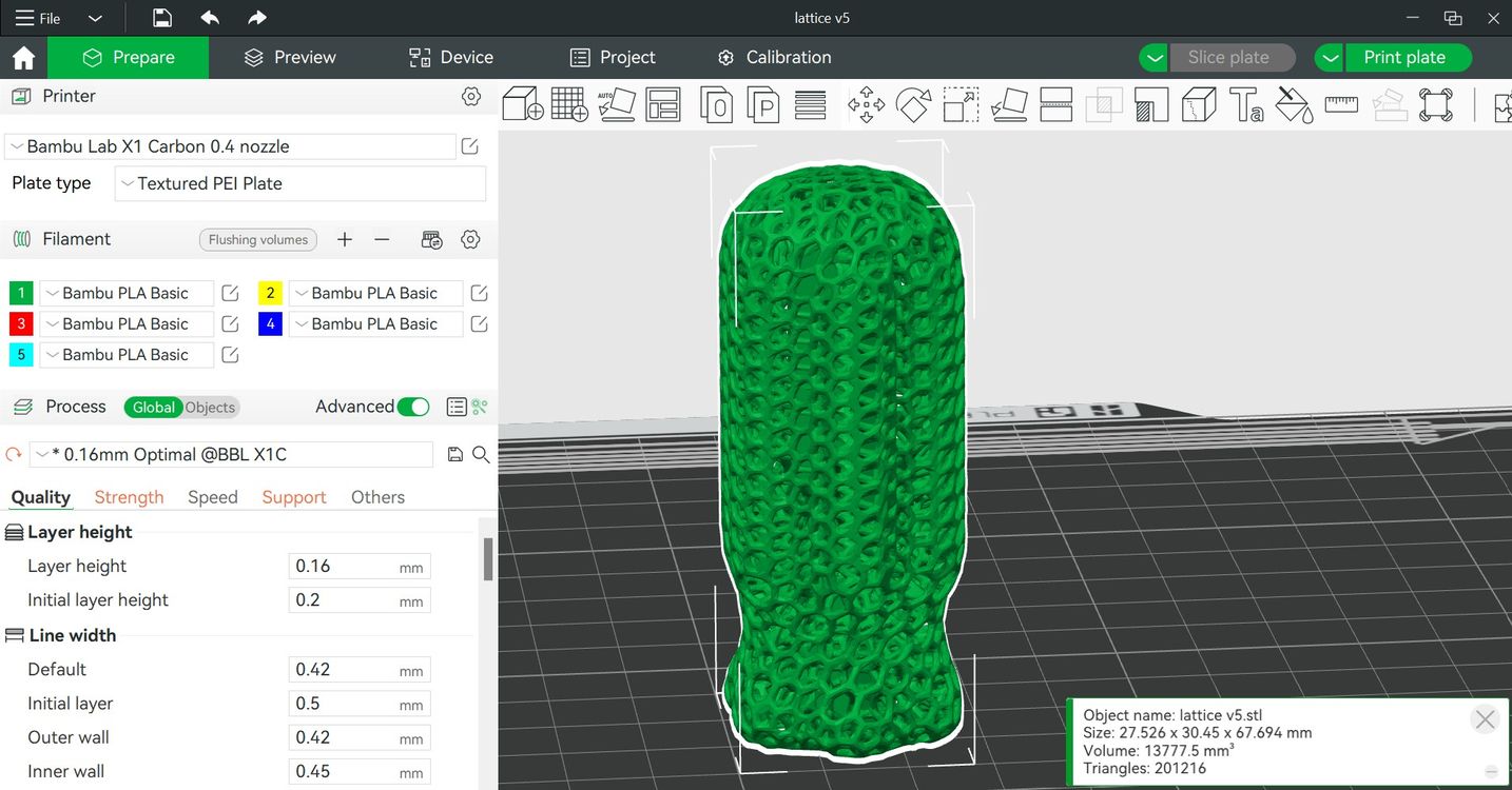
I use Bambu Studio as the slicer software to prepare the piece for printing. I use the following settings:
- Printer: BambuLab X1 Carbon
- Material: PLA HD Pacific Blue from Winkle
- Layer height: 0.16mm
- Extrusion temperature: 220°C
- Bed temperature: 60°C
- Supports enabled only from bed.
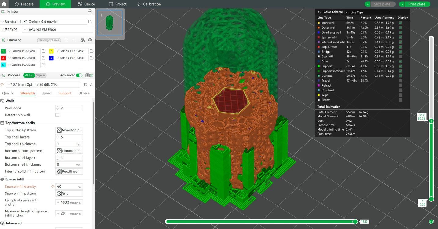
I use the wireless connectivity feature of Bambu studio to send the file to print.
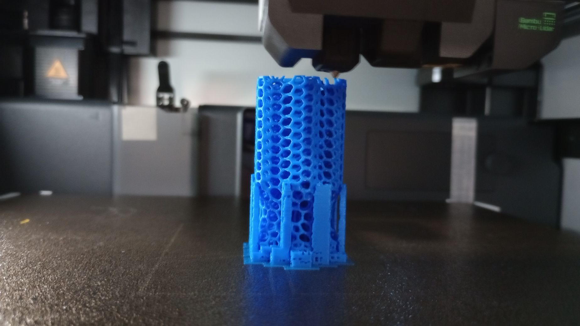
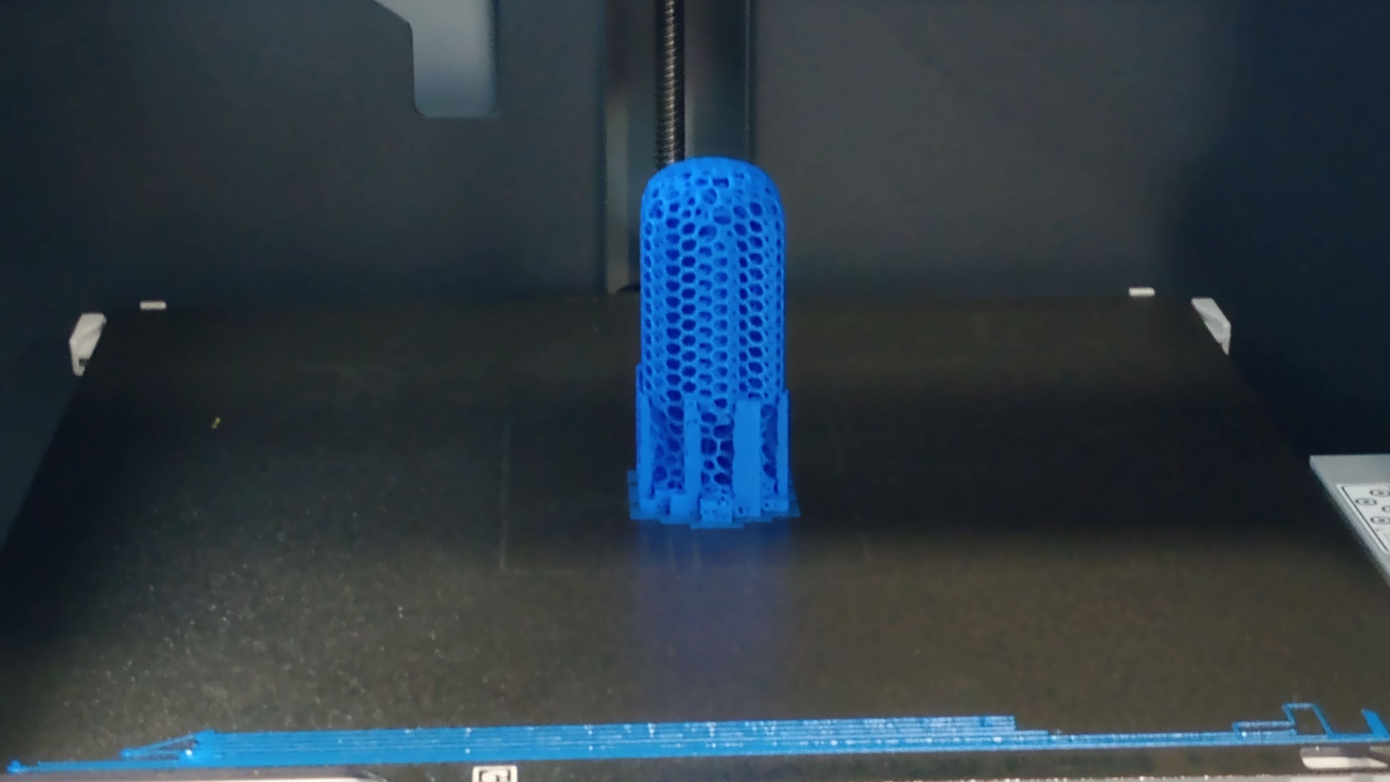
The printing took 2h 48m and 16.7g of filament.
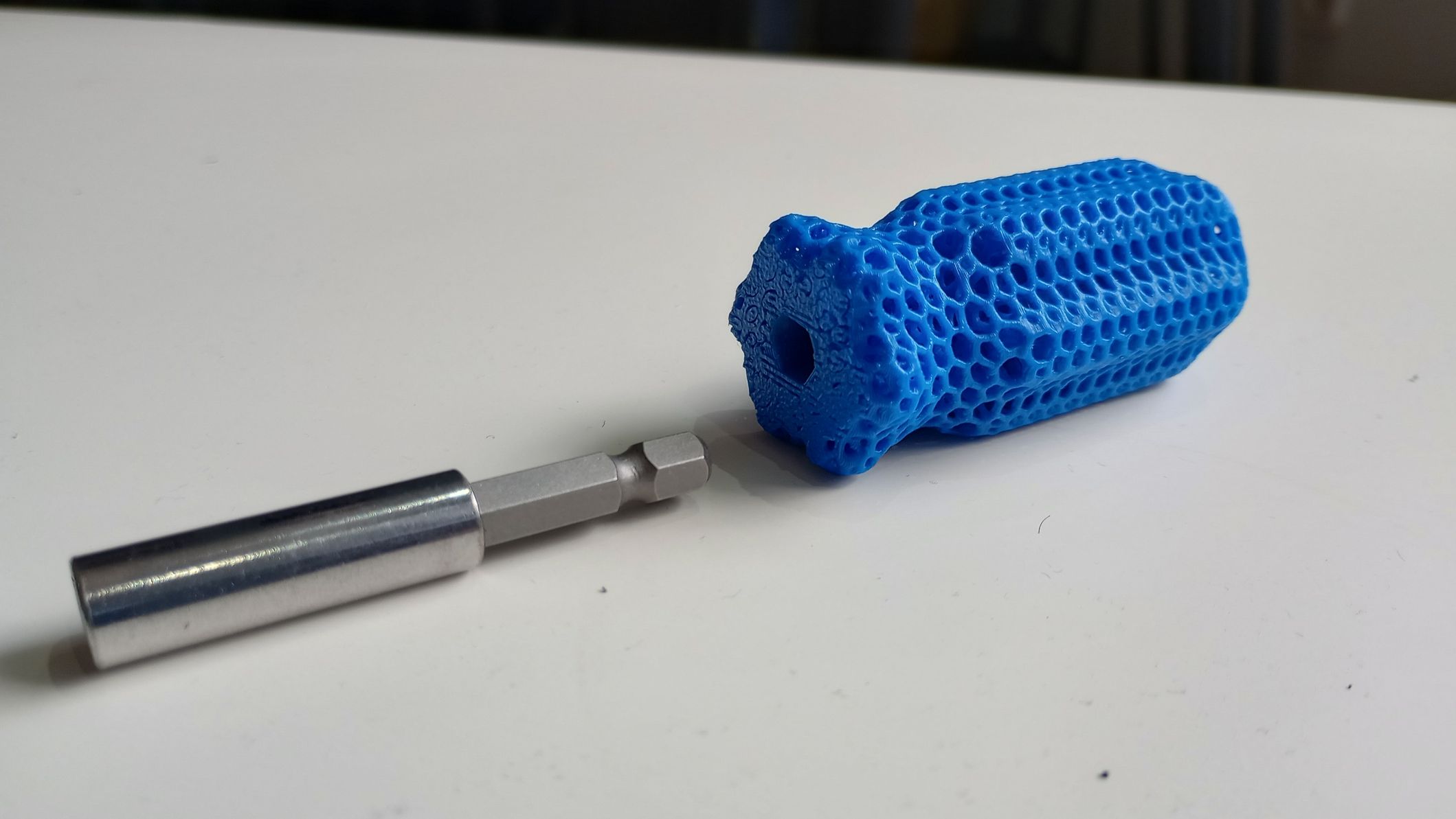
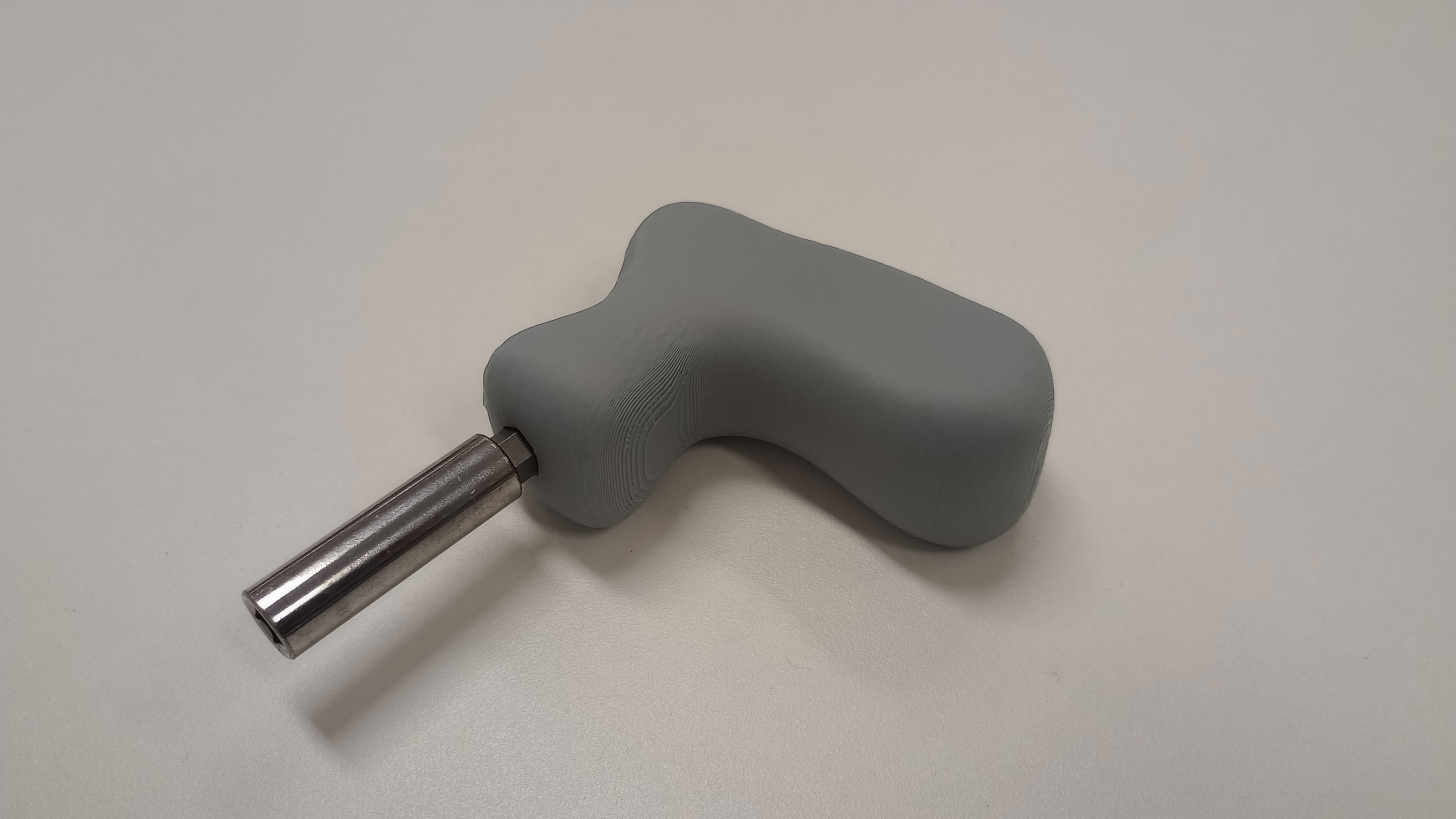
In this case, there is not much post-processing required for the printed part. I simply remove a few supports, and due to the high-quality print, there is no need for filing or sanding. The part feels strong and smooth in my hand. I use epoxy glue to attach it to the bit holder, and after a few minutes, I'm ready to take something apart!

3D Scanning
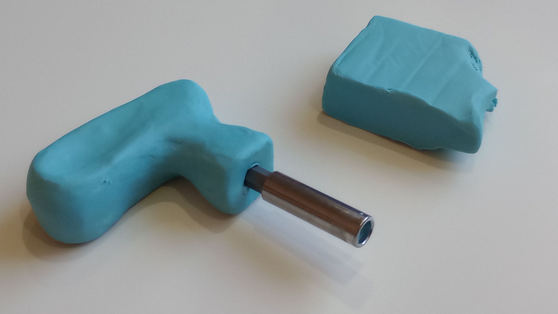
Since I don’t have access to a 3D scanner, I decided to use the app Polycam on an iPad. I am using the free features to capture an object through photogrammetry. For this scanning task, I modeled a new handle for a compact screwdriver using plasticine. My goal is to understand the workflow for scanning an object, editing it, and smoothing its surface so that it can be 3D printed.
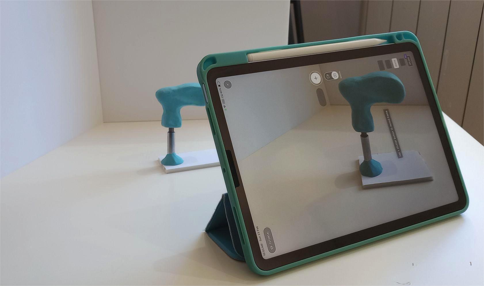
I make several attempts at scanning the screwdriver using the manual method, keeping the tablet static and rotating the object a bit every time. However, I get a failure message when processing the images.I believe this is because I moved the object flat and removed the base I was using to keep it standing.
The automatic feature, where you move around the object and the app automatically takes photos, provides better results for me. Before processing the images I activate the “Object Masking” option to ensure that no background is included in the capture.
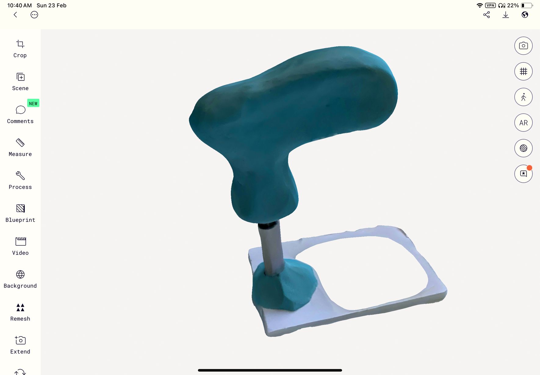
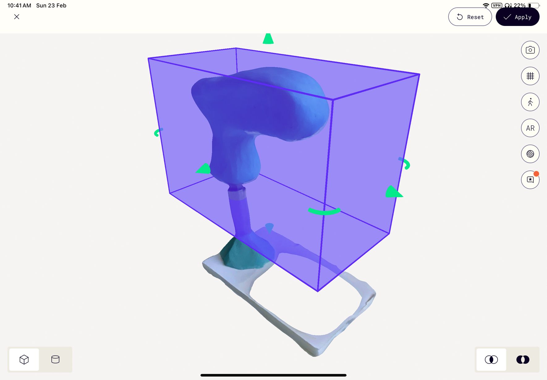
I use the crop tool to remove the unwanted support and I export the resulting model. The only file format available in the free version is .gltf so I use a online converter to export it as .stl.
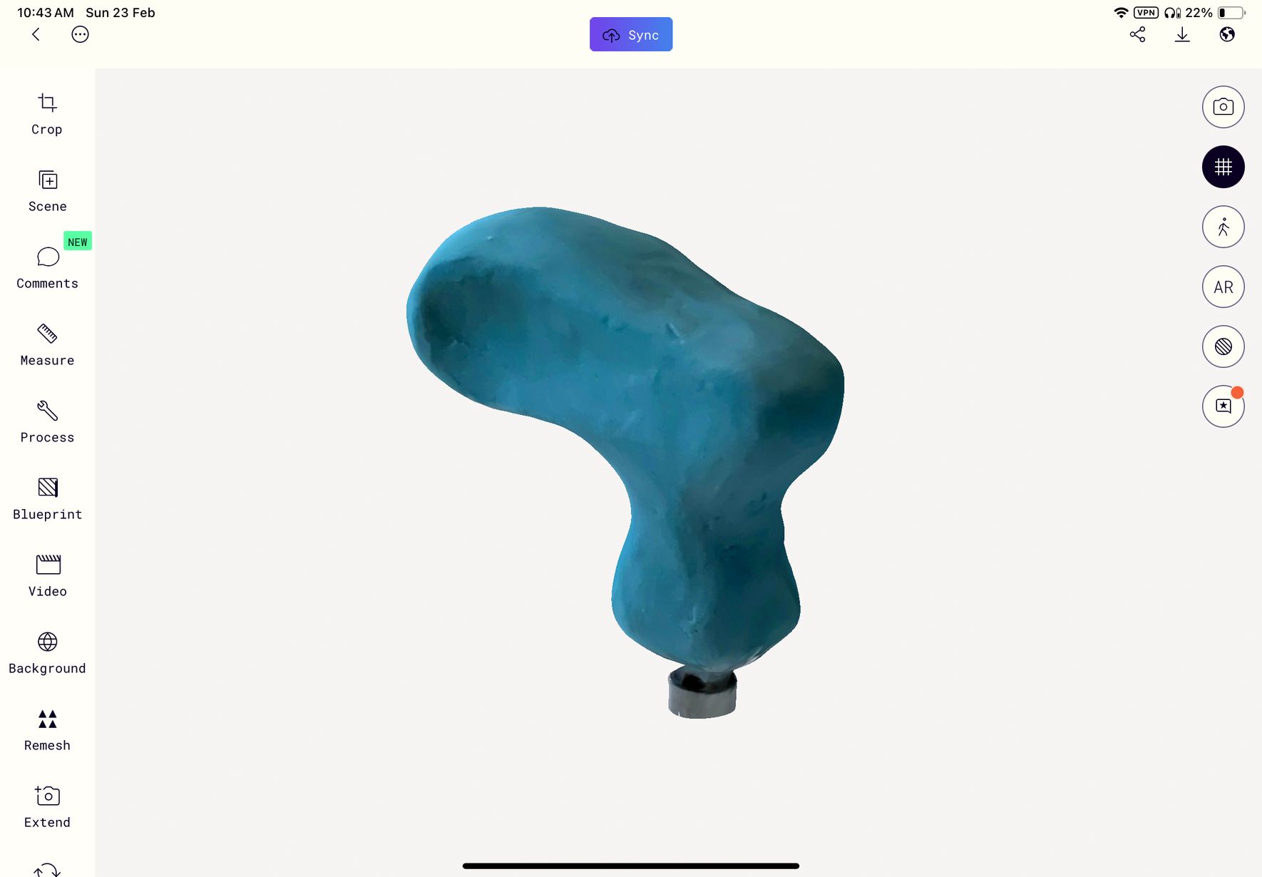
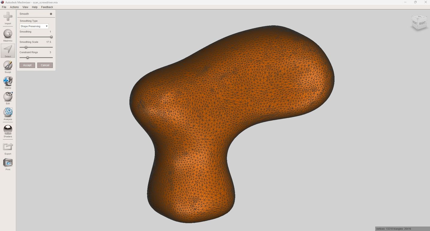
I use the Mirror tool to get a symmetrical side of the handle and the Smooth tool to smooth the whole surface and get rid of imperfections from the plasticine model that were captured by the scanning proces
Next, I reduce the mesh so it is easier to work with the model in Fusion.
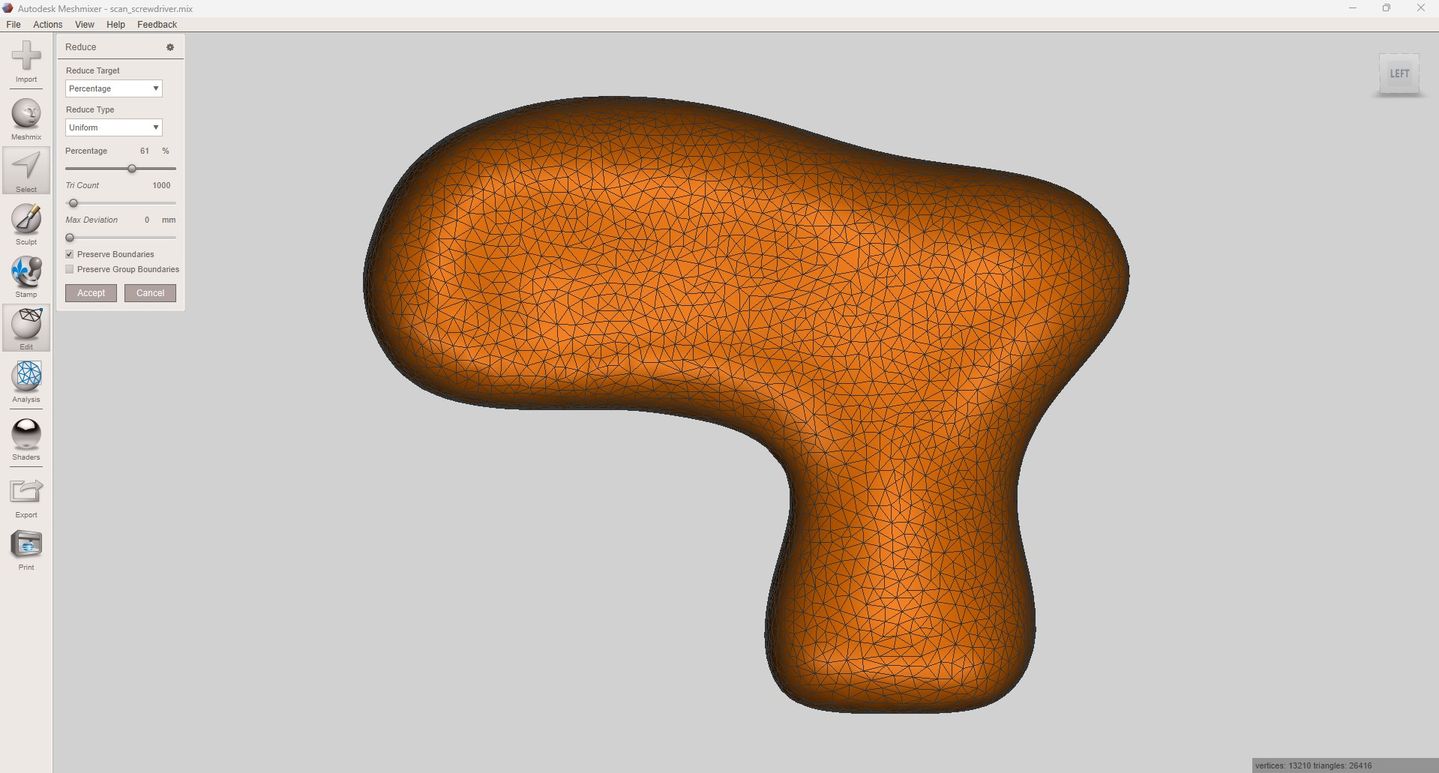
Next, I reduce the mesh so it is easier to work with the model in Fusion.
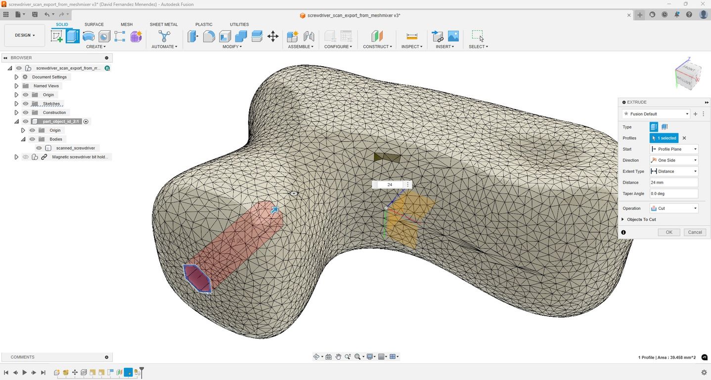
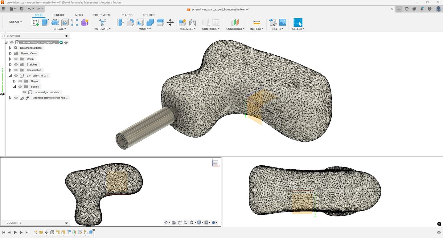
I import the model into Fusion, convert the surface into a solid, and cut a hole for the bit holder.
Next, I use the Bambu Studio slicer to prepare the handle for 3D printing with PLA in the Bambu X1 Carbon.
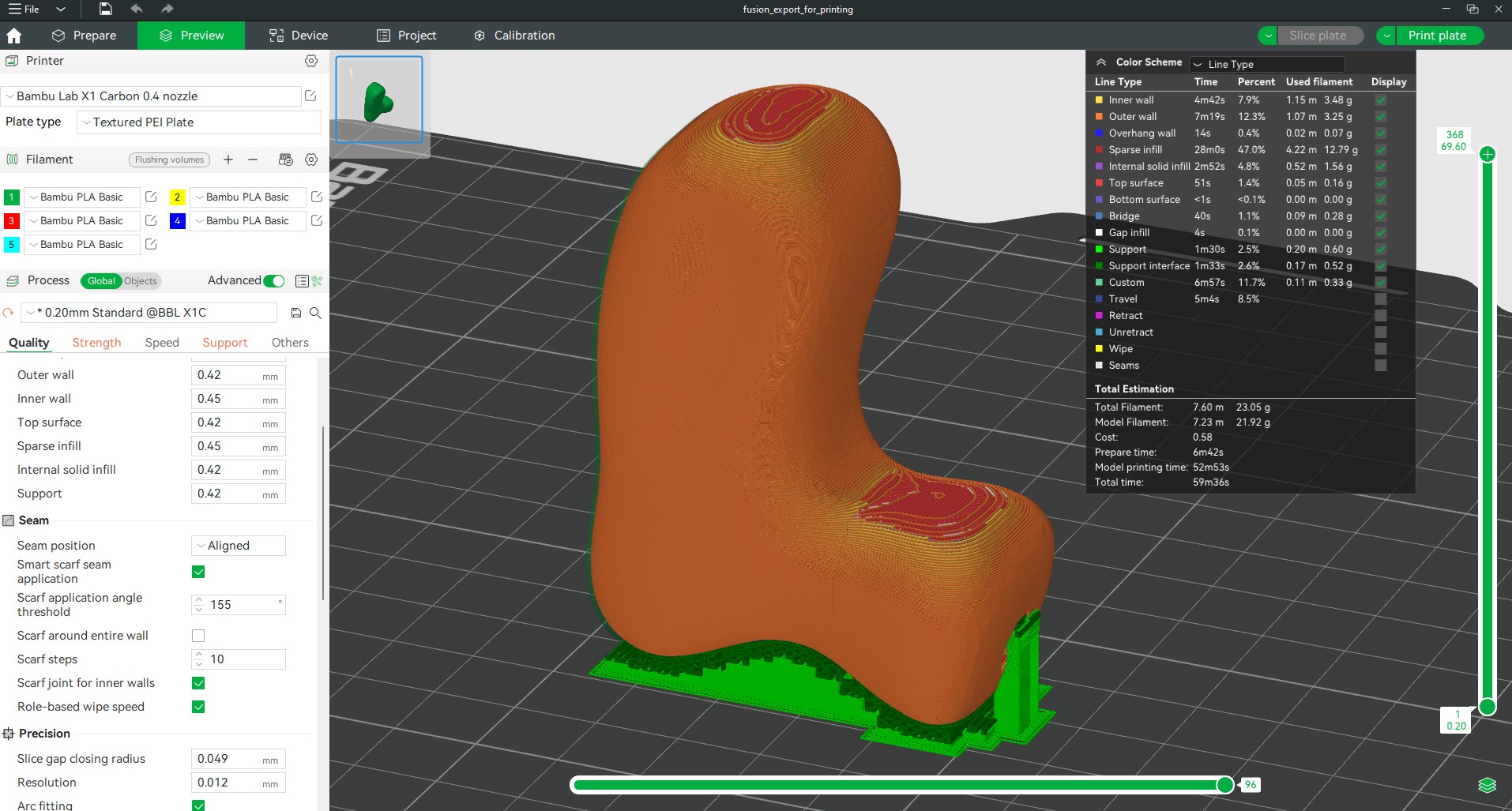
Printing settings:
- Material: PLA
- Layer height: 0.20mm
- Extrusion temp: 220 °C
- Bed temp: 55 °C
- Infill: honeycomb 20%
- Printing time: 53 minutes
- Supports + raft
The Bambu Studio app allows you to monitor the printing process with video and information about remaining printing time, filament used or temperatures.
Conclusion: Despite using an app with photogrammetry for scanning, I believe I achieved quite good results. Editing the mesh requires the use of 3D modeling software, such as Meshmixer, along with a CAD software (Fusion). Although the editing process can be cumbersome, simply printing the scanned file would not provide the same quality of results in this case. If I have a chance on one of my visits to Fab Lab León Fab Lab León, I would like to use their 3D Sense Scanner to compare the scanning workflow and results.
USEFUL LINKS AND RESOURCES
- 3D Printing Lattice Structures – The Ultimate Guide
- Design rules for 3D printers -Test files by Neil Gershenfeld
- Meshmixer Tutorial: Brake Lever Lattice
FILES
CAD model of screwdriver base design: CAD_screwdriver_base_design.step
CAD_screwdriver_base_design.stl
3D model of screwdriver handle with lattice structure: 3D_screwdriver_lattice_for_printing.3mf
3D_screwdriver_lattice_for_printing.stl
3D model of scanned object: 3D_scanned_object_file_for_printing.3mf
3D_scanned_object_file_for_printing.stl
Top