Week 02. Computer-Aided Design
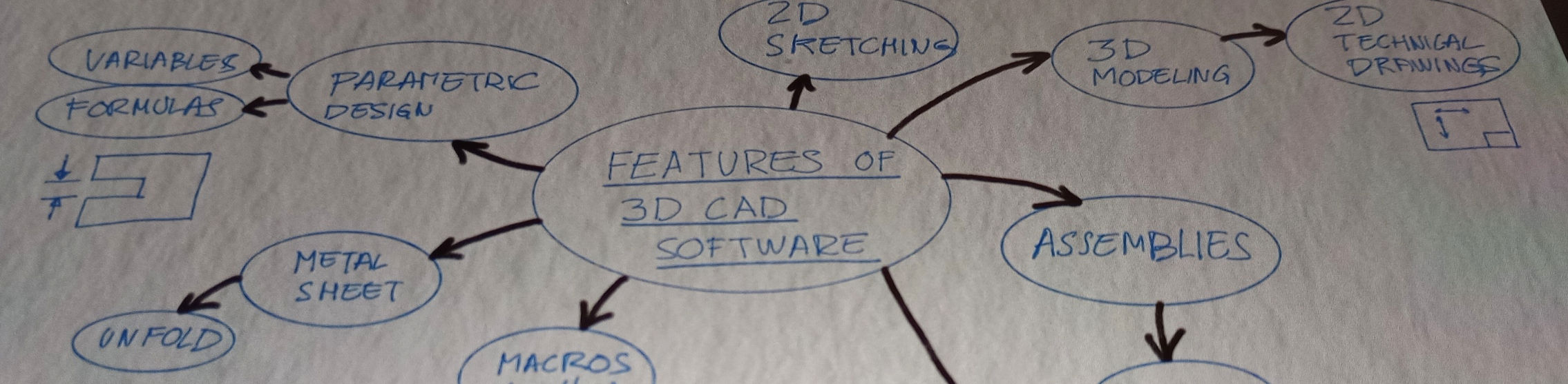
Table of Contents
- WEEKLY PLAN
- COMPUTER-AIDED DESIGN
- CAD MODEL OF FINAL PROJECT
- RENDERING AND ANIMATION
- IMAGE AND VIDEO COMPRESSION
- USEFUL LINKS AND RESOURCES
- FILES
- REFLECTION
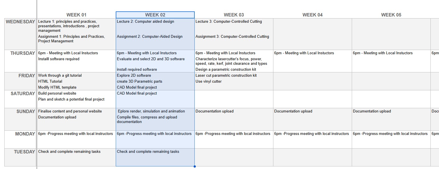
WEEKLY PLAN
- Model (raster, vector, 2D, 3D, render, animate, simulate, ...) a possible final project.
- Document how to compress image and video files.
- Demonstrate and describe processes used in modelling with 2D and 3D software.
- Upload documentation to the class archive
COMPUTER-AIDED DESIGN
2D DESIGN SOFTWARE
PROCREATE
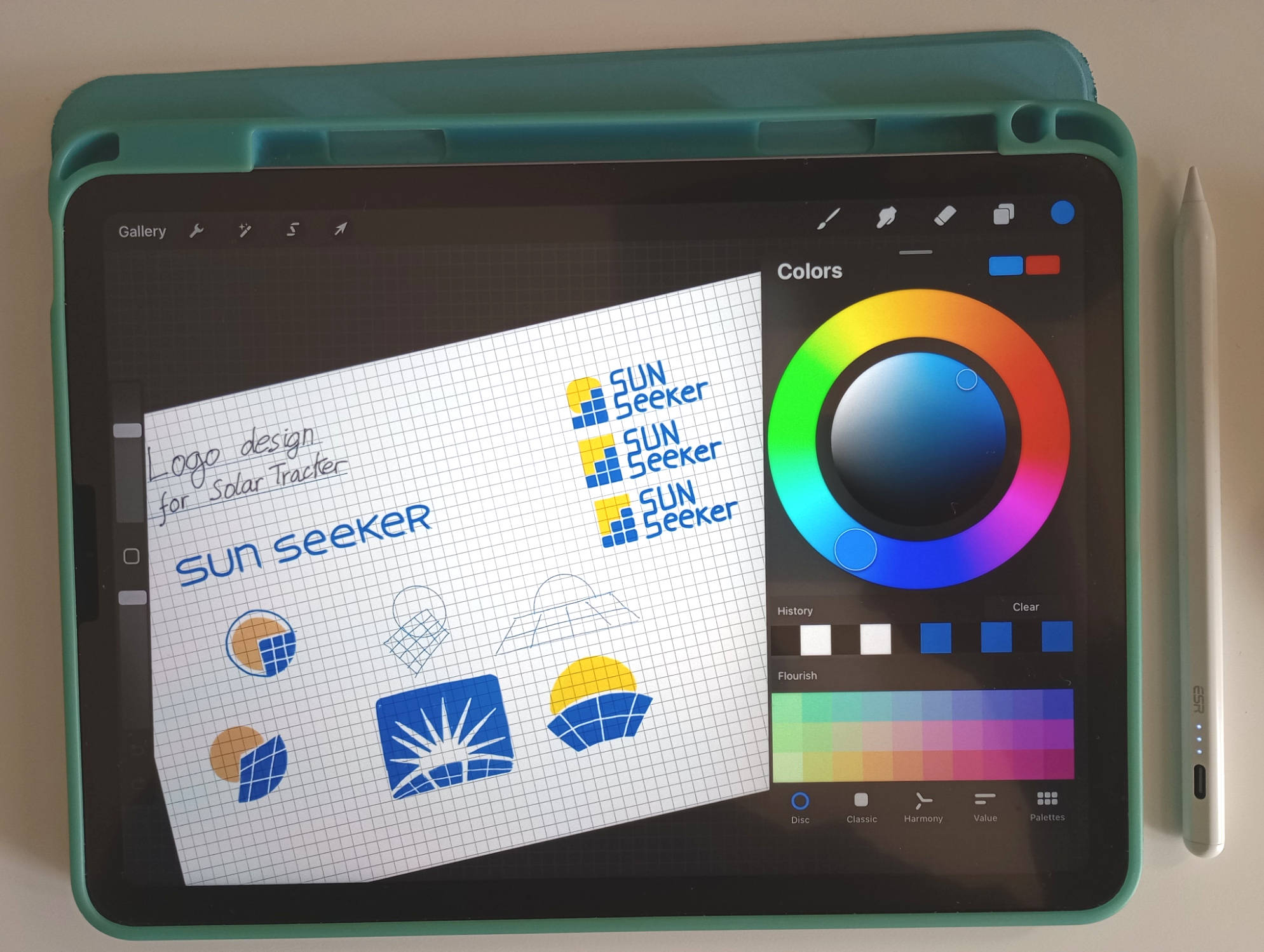
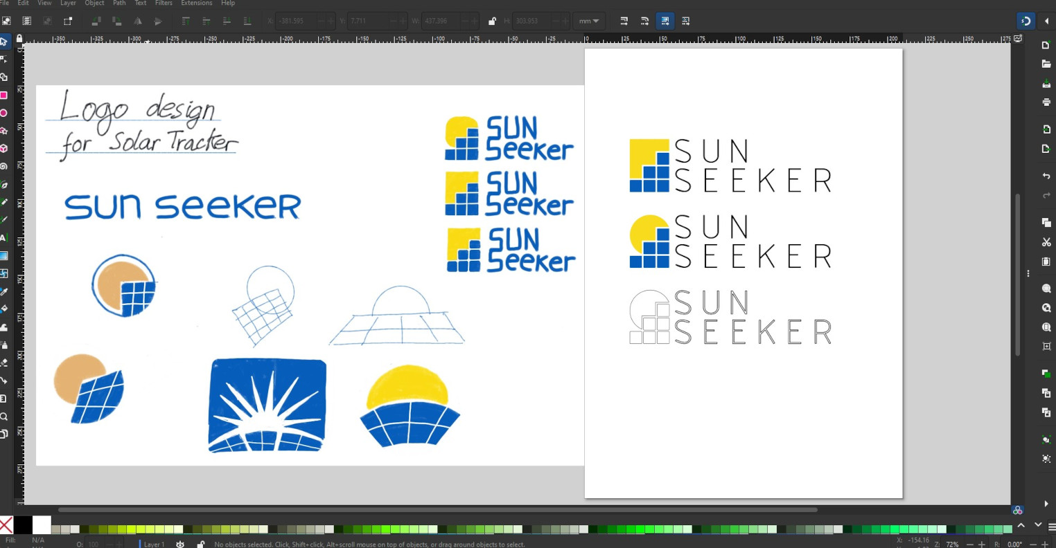
Procreate is a raster graphics app designed for the iPad, enabling users to sketch and create digital art.
I have utilized Procreate to hand-draw a potential logo design that could serve as a brand identity mark for my final project, which involves designing and constructing a dual-axis solar tracker.
In Procreate, you use a stylus pen, and the app offers a variety of brushes and layering tools.
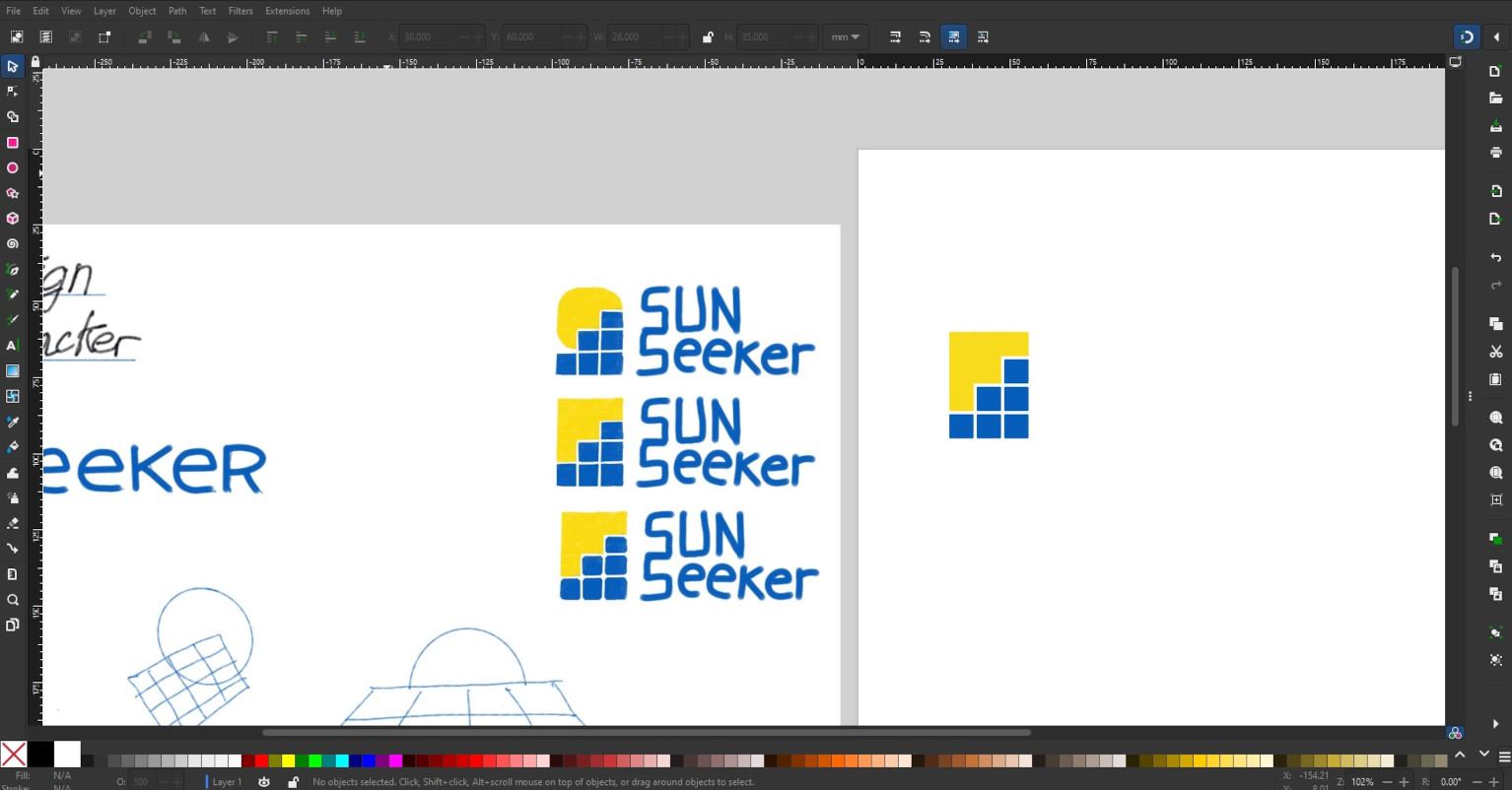
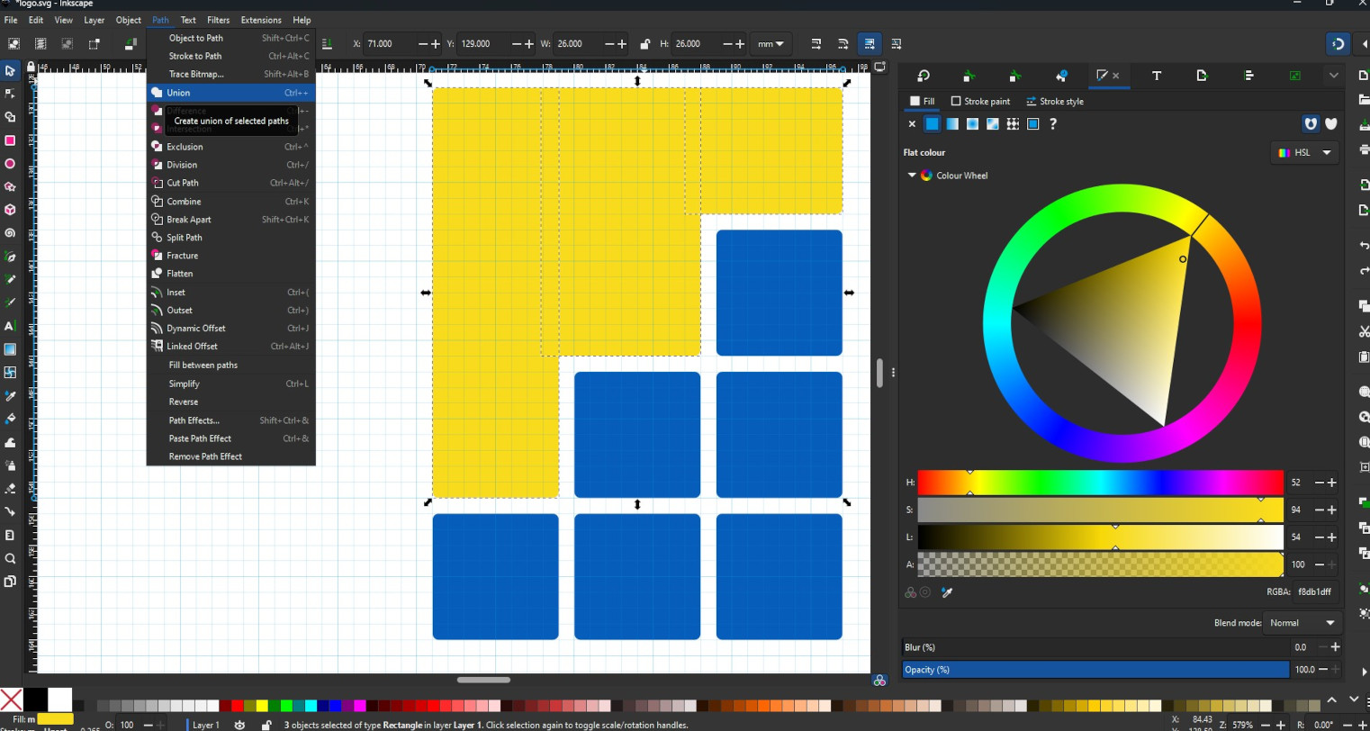
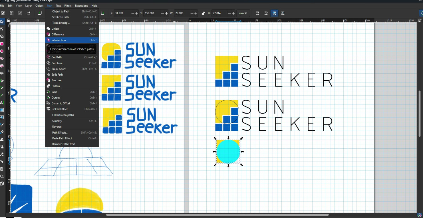
INKSCAPE
I exported the designs from Procreate as JPEG files and imported them into Inkscape. Inkscape is a free, open-source vector graphics software used for creating illustrations and artwork. Since it works with vector graphics, the designs can be scaled without losing quality, a common issue with raster graphics.
I decided to use Inkscape to replicate one of the designs I sketched in Procreate. I employed the grid and snap features to draw simple shapes that were evenly spaced. Additionally, I used boolean operations to join or intersect shapes, allowing me to create more complex designs. The text tools were also used to adjust the font and line spacing.
Although I didn't use this feature in my project, Inkscape can vectorize bitmaps. The vector paths generated in Inkscape can be utilised for 2D digital manufacturing processes, such as laser and vinyl cutting.
FREECAD (2D)
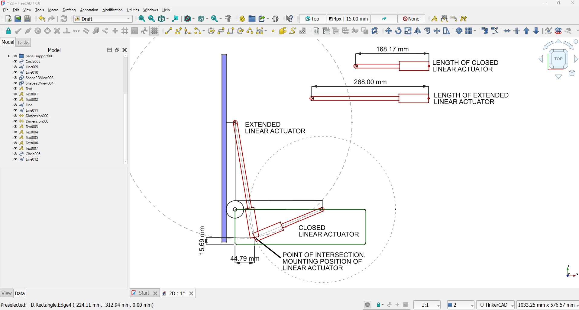
FreeCAD offers a useful 2D drawing environment with tools for creating precise drawings that include dimensions and constraints. There are two workbenches available for 2D drawing: Draft and Sketcher. While they share similar tools, each has its own unique features, which can be somewhat confusing. For instance, in Sketcher, you can select elements using a selection window, whereas this option is not available in Draft. Additionally, you can select and drag elements in Sketcher, but in Draft, you must use the move command.
I explored the Draft Workbench in FreeCAD to study the ideal fixing points for a linear actuator designed to move a solar panel from 0 to 90 degrees.
 Top
Top
3D CAD SOFTWARE
To evaluate different 3D CAD software I am going to model a part that is going to be used in the 3D model of my final project. This part is a linear actuator, but since I still haven´t decided on the size and model, I am going to try and create it as parametric part. I will also add a joint to represent the sliding movement of the rod.
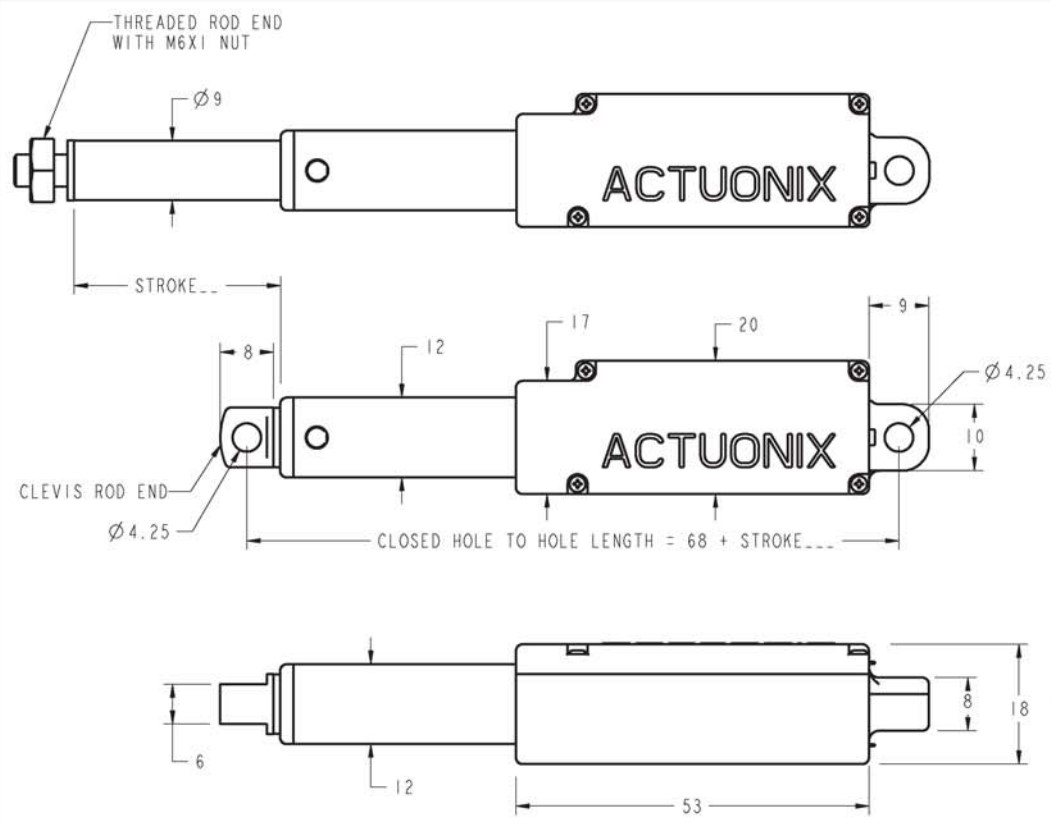
As a reference I am going to use the data sheet from linear actuator Actuonix L16.
ONSHAPE
Onshape is a cloud-based CAD software that includes tools for sketching, 3D modelling, assembly design, joints, drawings, simulation and renderings.
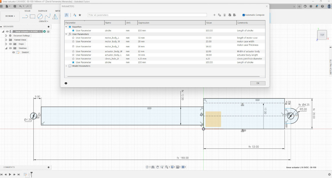
When creating a sketch, you can use a table to set variables such as actuator body length, thickness, and stroke distance. These variables can then be used in the dimensions, allowing for easy modifications of the design by changing the value of the variables.
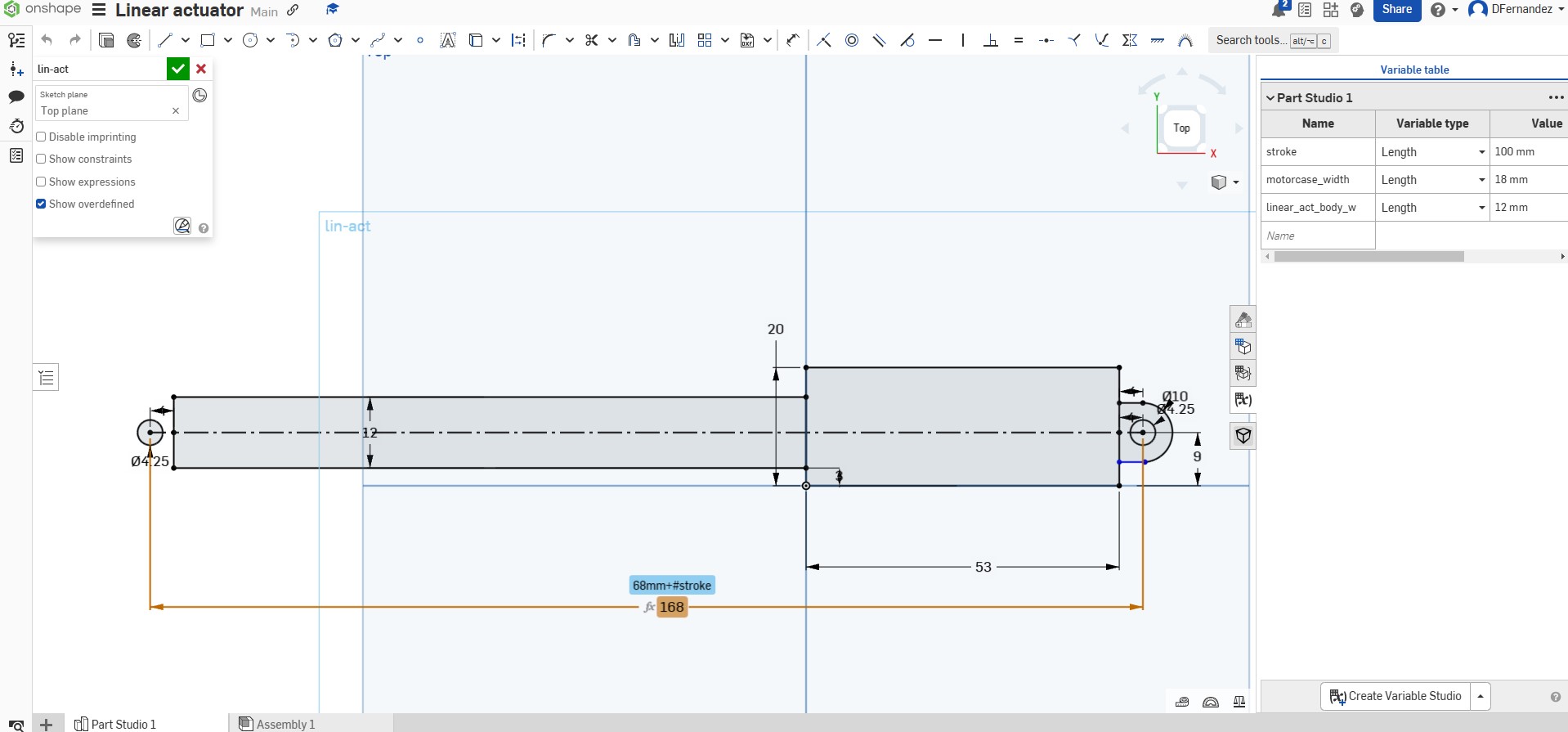
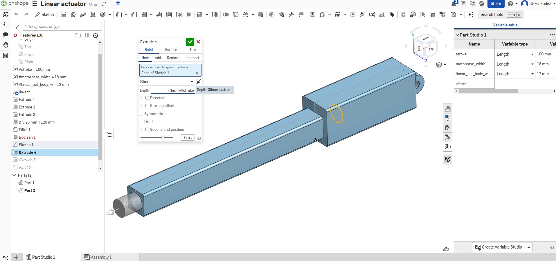
When extruding the geometry from the sketch you can also use variables.
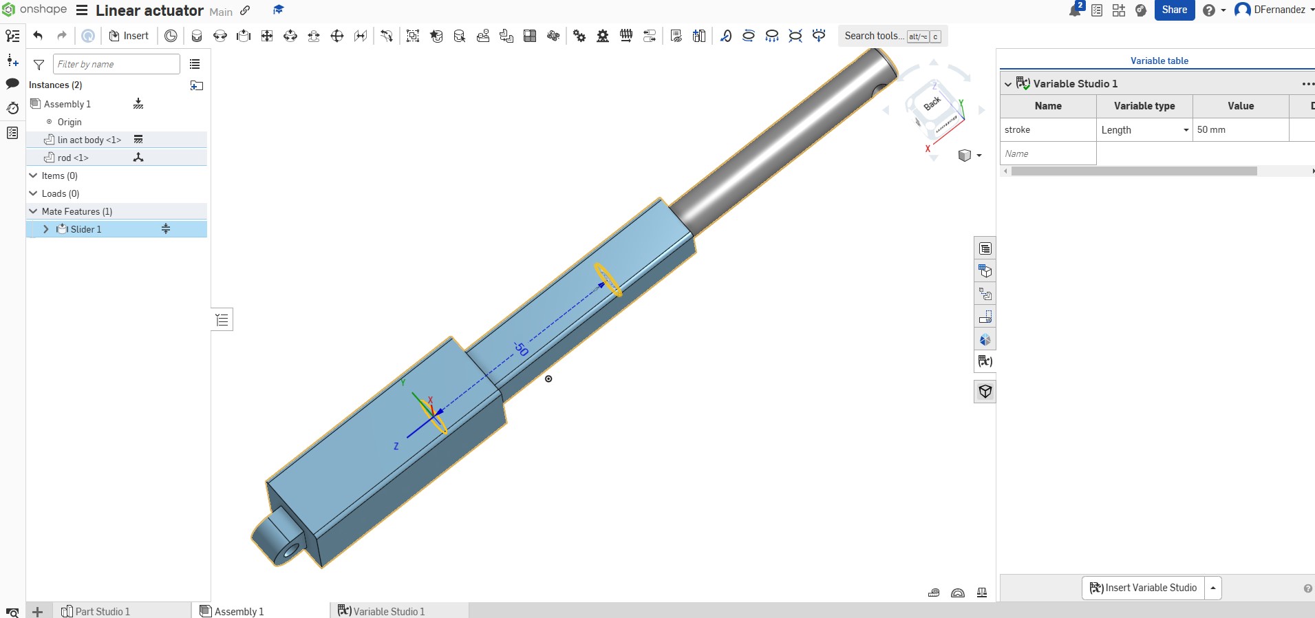
To apply joints, you must first create an assembly. There are various types of joints available; in this case, I will use the Slider Mate joint.
The maximum movement of the rod can be defined by a variable, which means that not only the dimensions of the linear actuator change, but the stroke length of the joint is also updated accordingly.
Overall, using Onshape was a seamless experience, and although I was not that familiar with this software, I didn’t require any tutorials.
FUSION
Fusion is another cloud-based CAD tool that offers features for product design, engineering, and manufacturing.
The workflow for creating the parametric design of the linear actuator closely resembles that of Onshape.
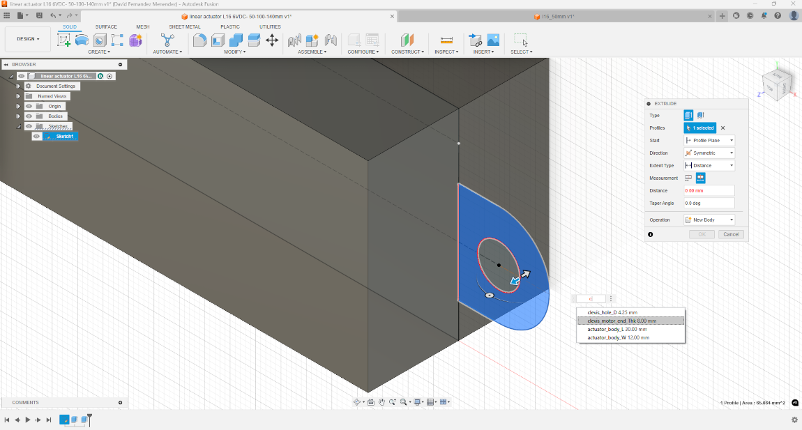
First, I created a sketch incorporating constraints and parametric values.
When extruding the sketch I can also make use of parametric values.
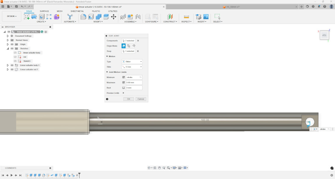
And when applying the Slider joint I could define the maximum motion limit using the stroke variable.
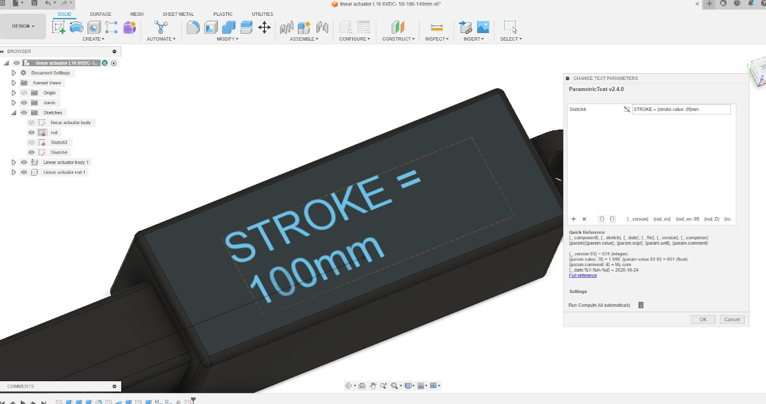
Additionally I found a Add-in that allows you to create parametric text that can then be embossed on the design. In this way I managed to make a parametric design that changes the dimensions of the linear actuator, modifies the motion limits of the joints and updates the engraved text to show the stroke length of the actuator.
The following video shows how easily the design can be modified changing the parametric values.
TopFREECAD
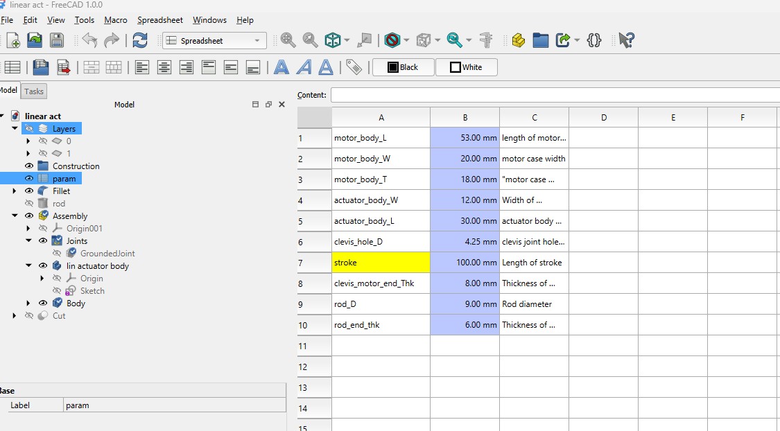
FreeCAD is an open-source, parametric 3D modeling software. Having previously used the 2D drafting environment, I am now exploring the parametric and 3D modeling capabilities of the software.
I used the Sketcher workbench to create geometry by applying constraints and the parametric variables defined in the Spreadsheet. This process took longer than with other software I evaluated because applying constraints was not as intuitive, and I encountered an error when trying to create a solid. The issue arose because the areas were not fully enclosed; it appears that the two rectangles need to have overlapping coincident edges. This is not required in Fusion or Onshape.
It would also be beneficial to see the areas filled with color when they are closed and ready to be extruded as it happens in other CAD platforms.
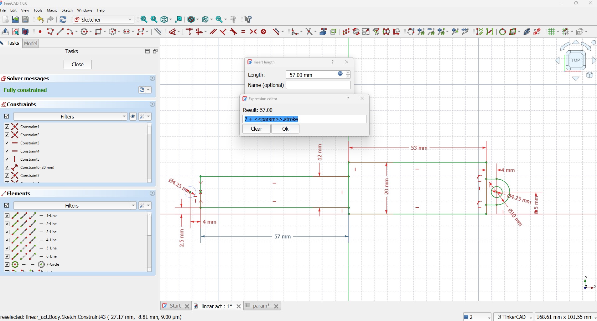
When extruding a 2D geometry, you can apply parametric values to define the depth of the extrusion. However, I discovered that it is not possible to extrude different areas of the same sketch, which means I cannot apply varying thicknesses as I was able to do before. This is quite cumbersome, as I would need to create 3 separate sketches to achieve the same solid that I previously generated using other software with just 1 sketch
Additionally, I am a bit confused about the use of the Part Design and Part Workbenches. I find myself switching between these two workspaces too often.
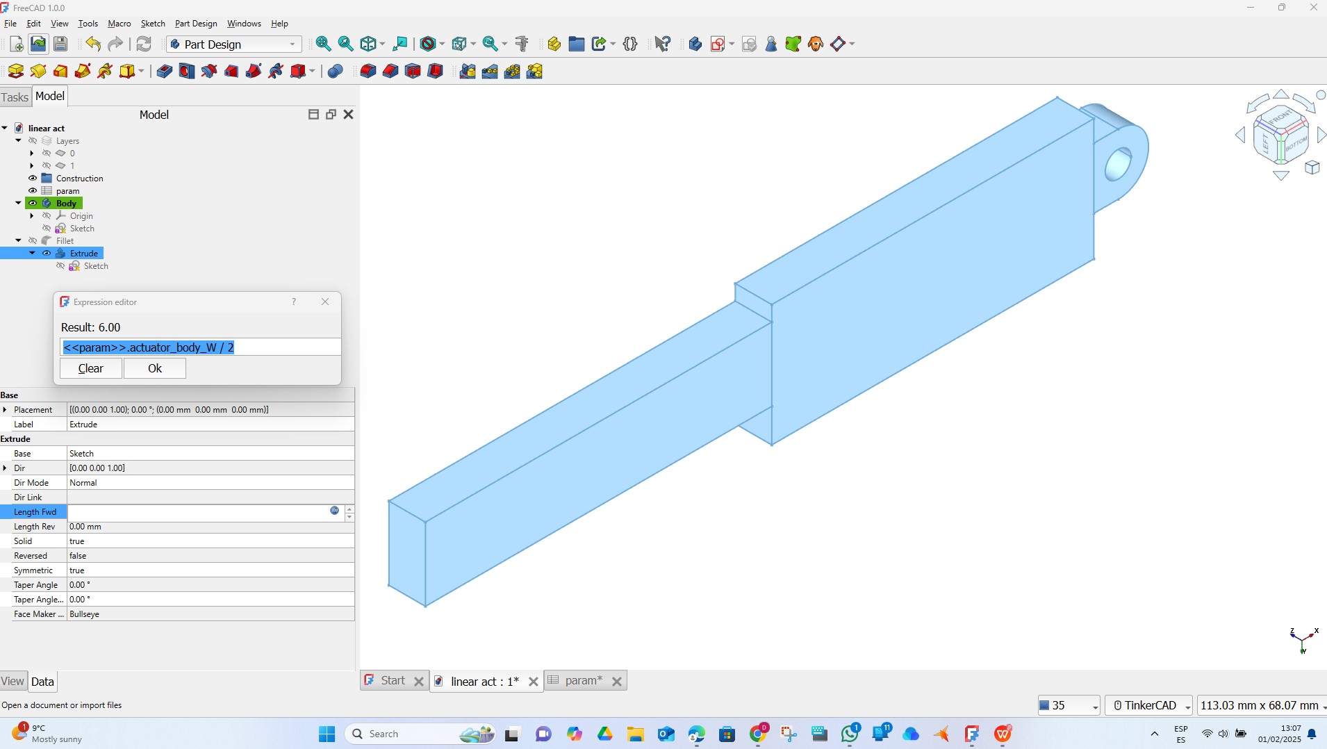
In the Part workbench, I create another extrusion to make a hole for the rod. Then, I use a Boolean operation to remove one part from another.
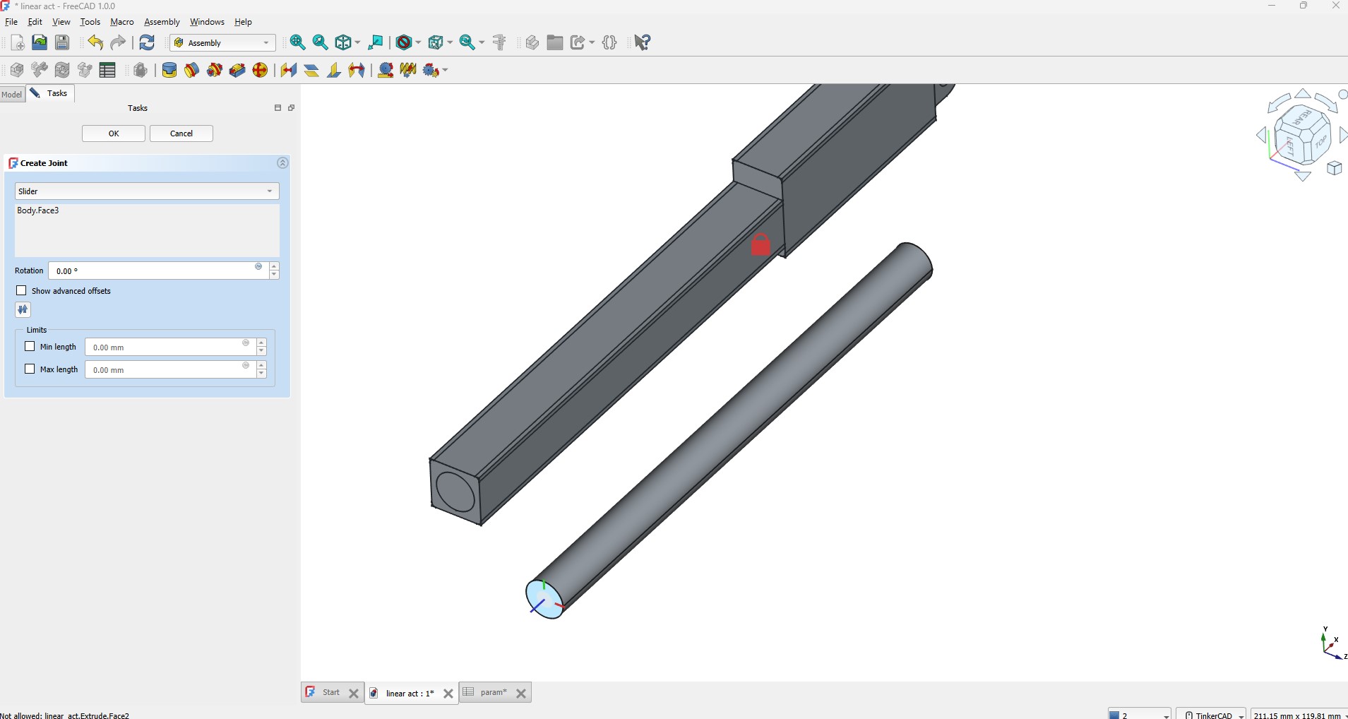
I then moved to the Assembly Workbench to create the slider joint, but I encountered some additional problems. I was able to ground one of the parts, but when I attempted to create the joint, I couldn't select the contact faces from the grounded part.
I watched a FreeCad Tutorial for joint in assembly, but I still couldn't resolve the issue. I've spent too many hours in FreeCAD, and I'm running out of time. I'm afraid we may need to part ways for now, as I find this platform neither intuitive nor productive
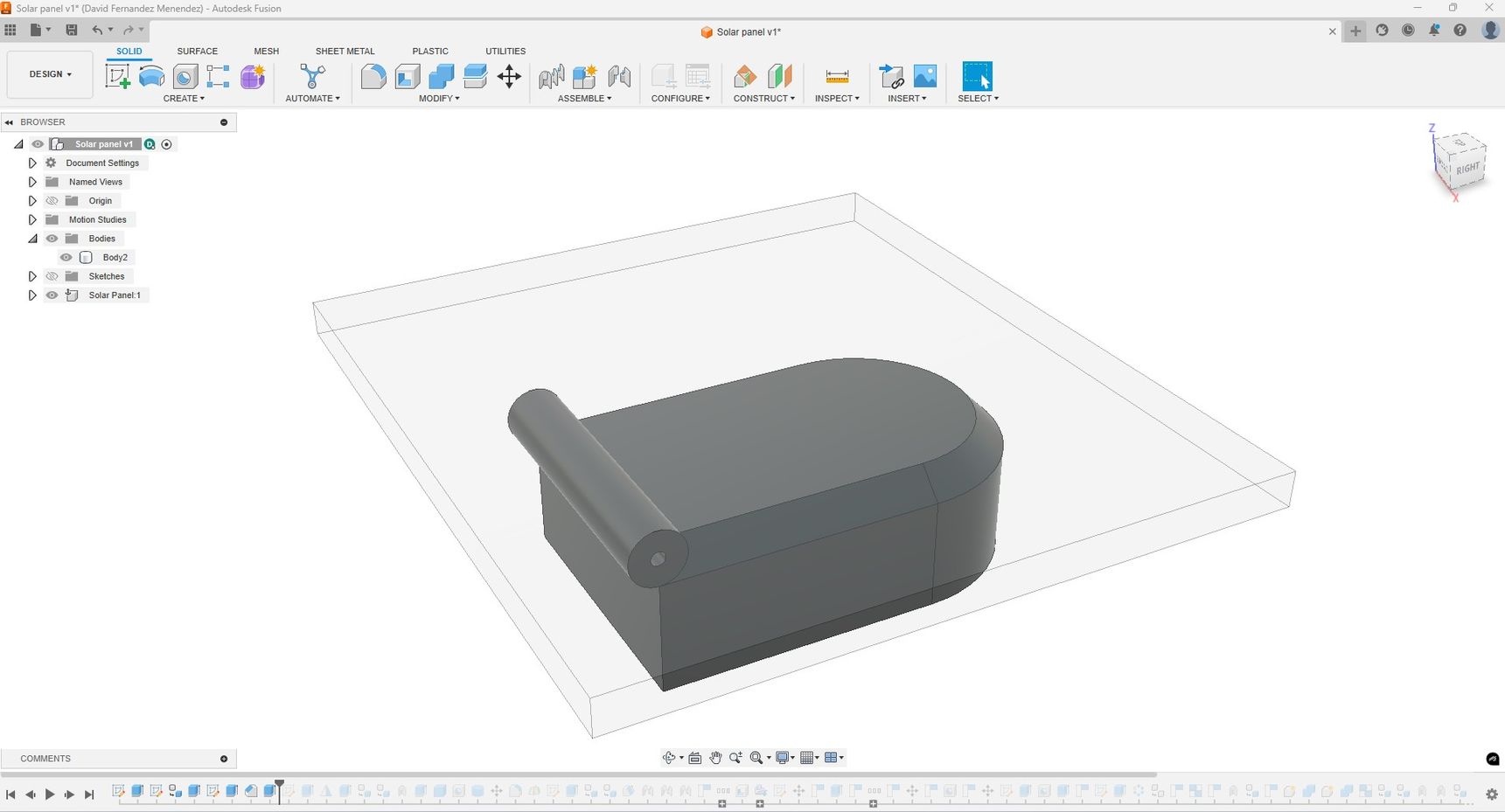
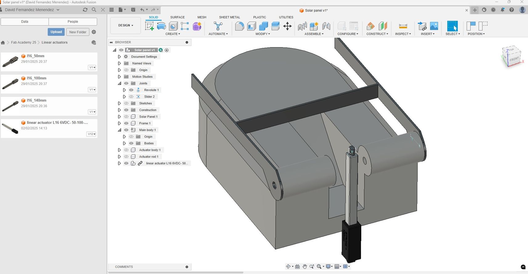
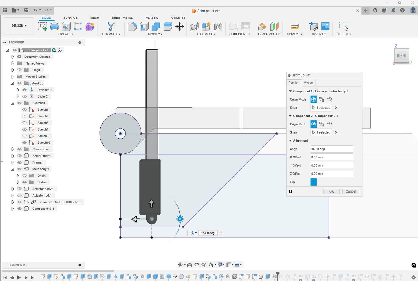
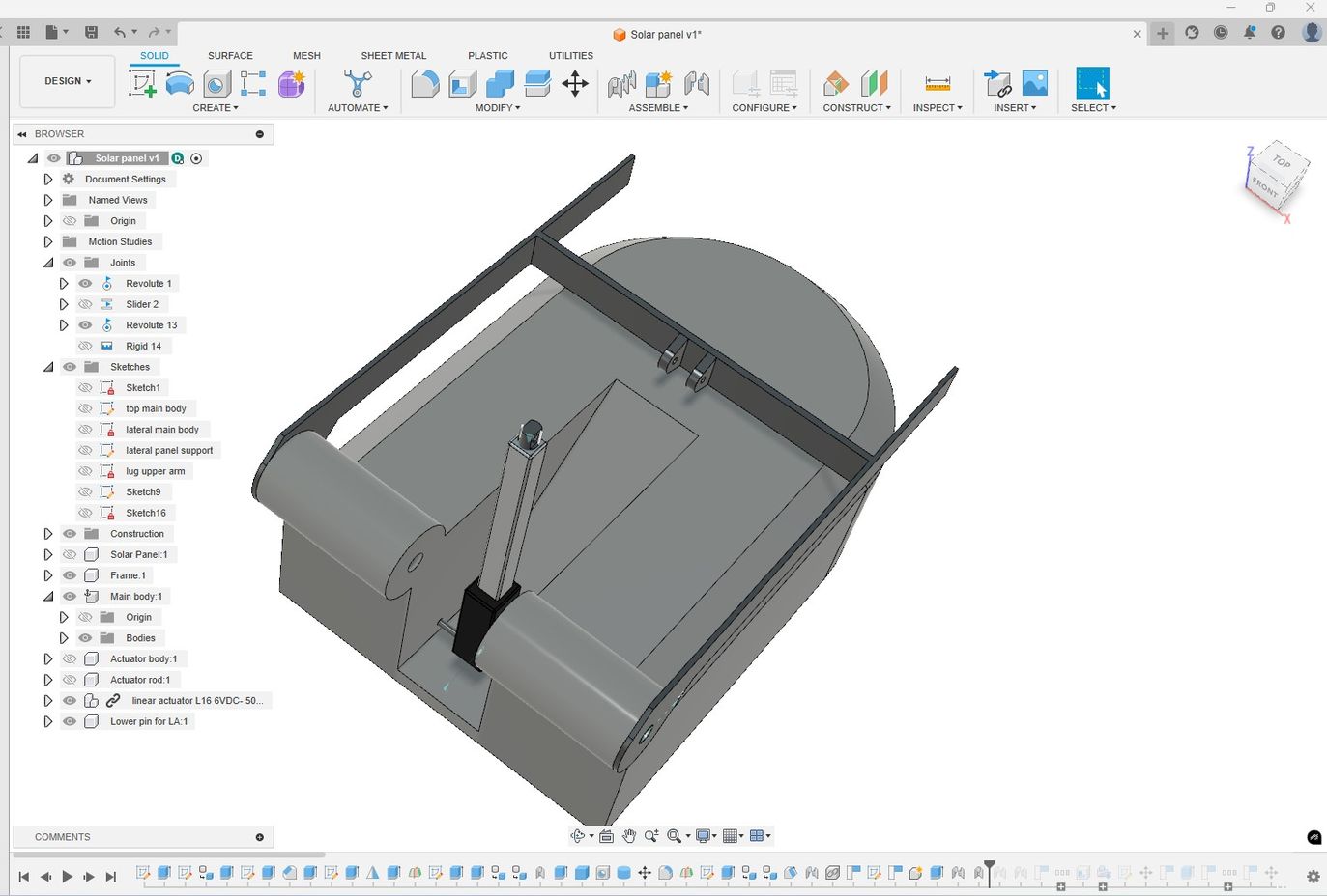
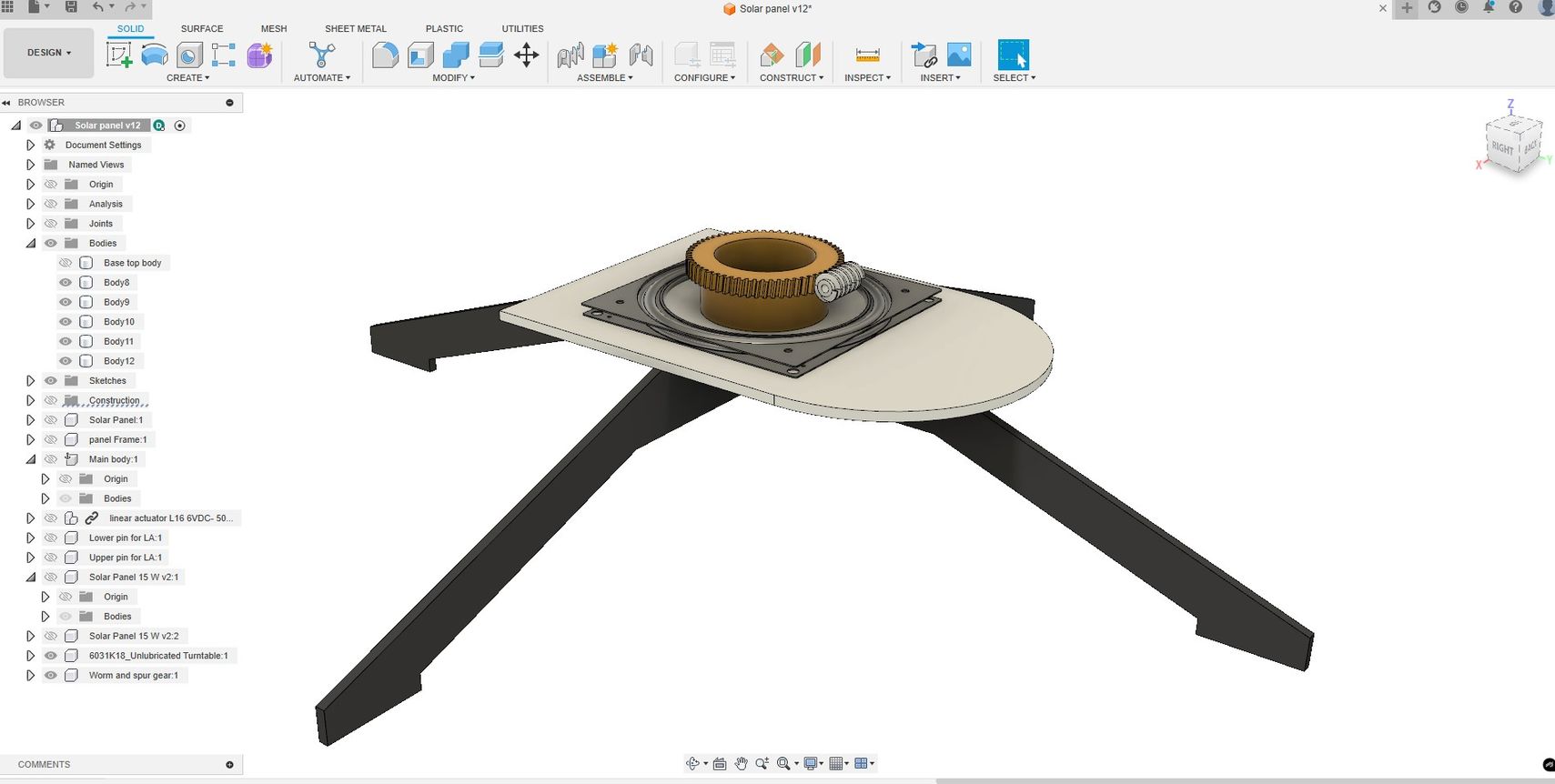
CAD MODEL OF FINAL PROJECT
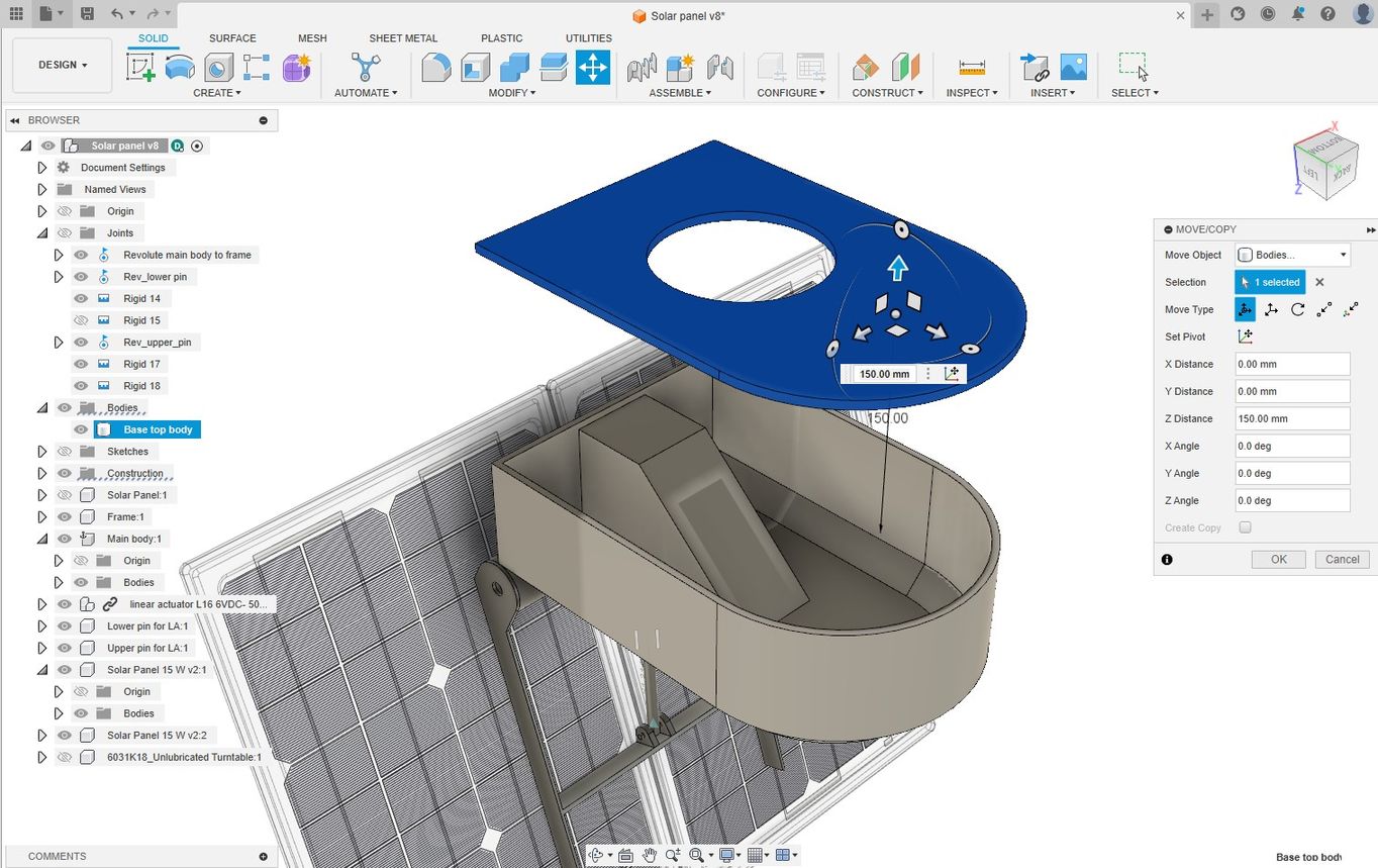
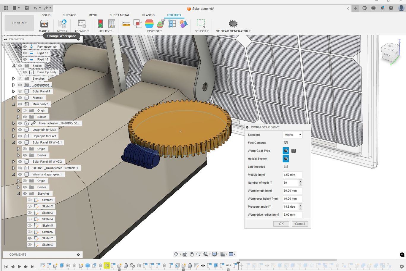
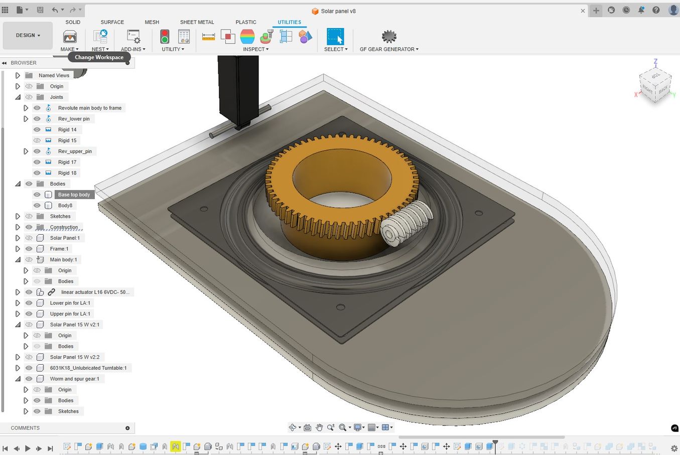
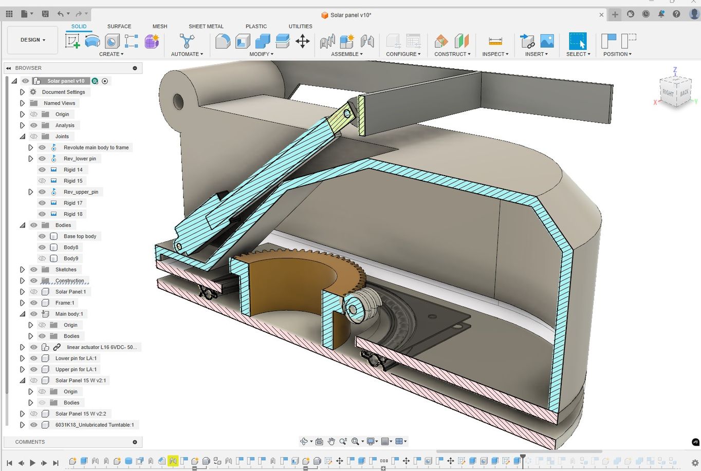
The following screenshots illustrate the modeling process I used in Fusion to create a 3D model for my final project. I used several features of Fusion, including parametric values, gear generation, section views to check for clashes and adding joints.
I imported the following parts from online CAD repositories:
I also imported the parametric linear actuator I developed in the previous section and applied joints to enable the panel to rotate around the elevation axis.
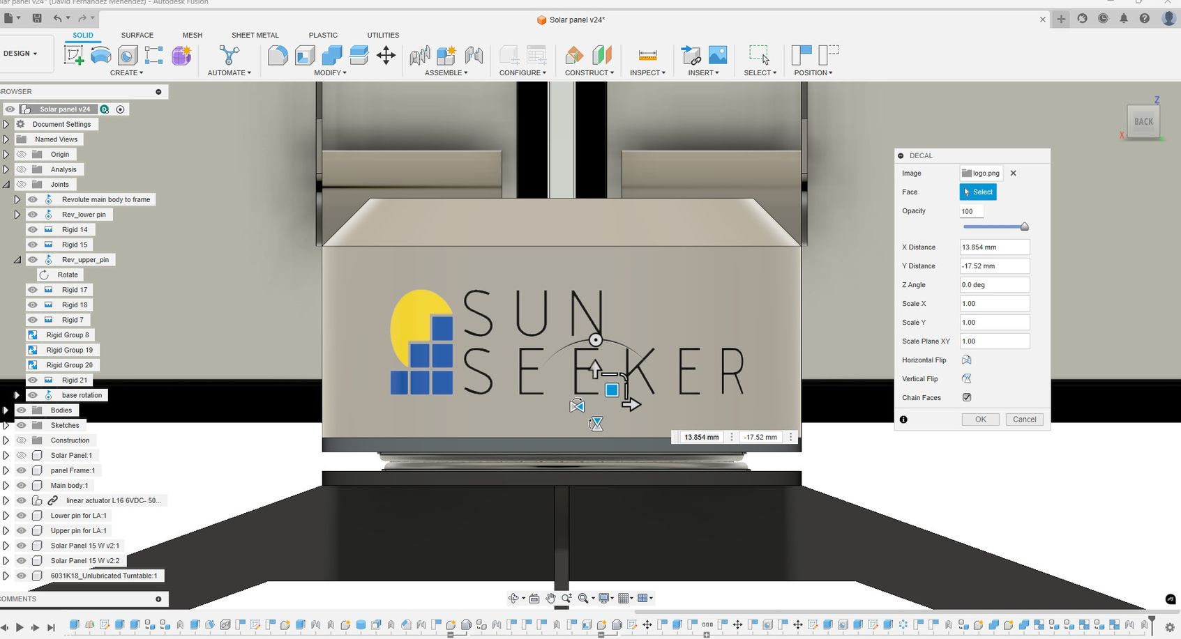
Finally, I incorporated the logo design I created in Inkscape as a decal so it would appear in the renderings.
This is an early version of the 3D model of the project idea, and further modelling and details are required. For example, a cover for access to electronics, fixing systems for solar panels, a folding system for legs, motor and electronic parts, fasteners, and fixings.
RENDERING AND ANIMATION
To create realistic renderings and animations, I continued using Fusion, as it offers workspaces specifically designed for these tasks. While it doesn't have all the features of dedicated visual effects software, it provides a straightforward way to generate effective renders and video animations.
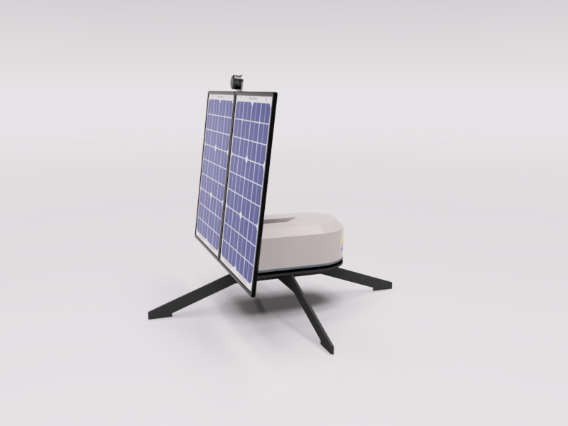
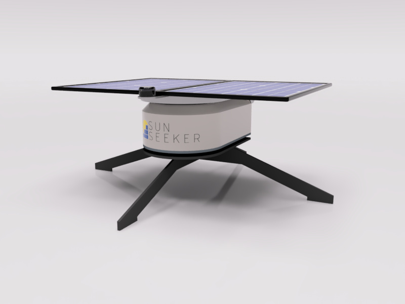
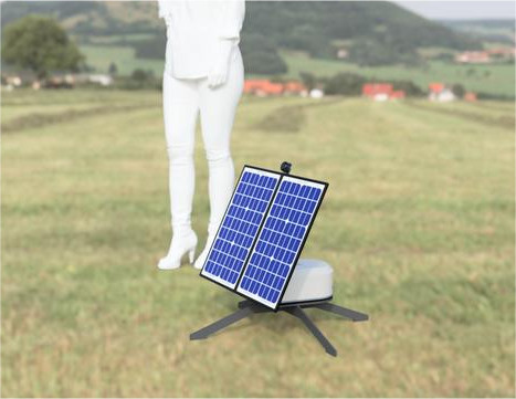
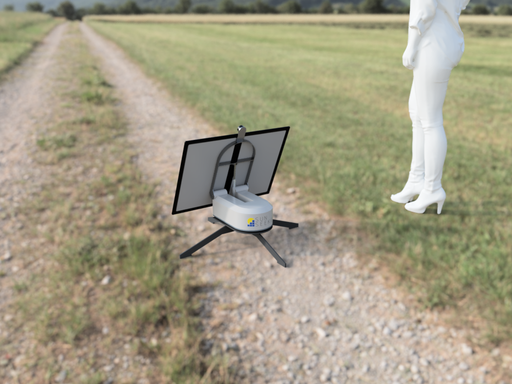
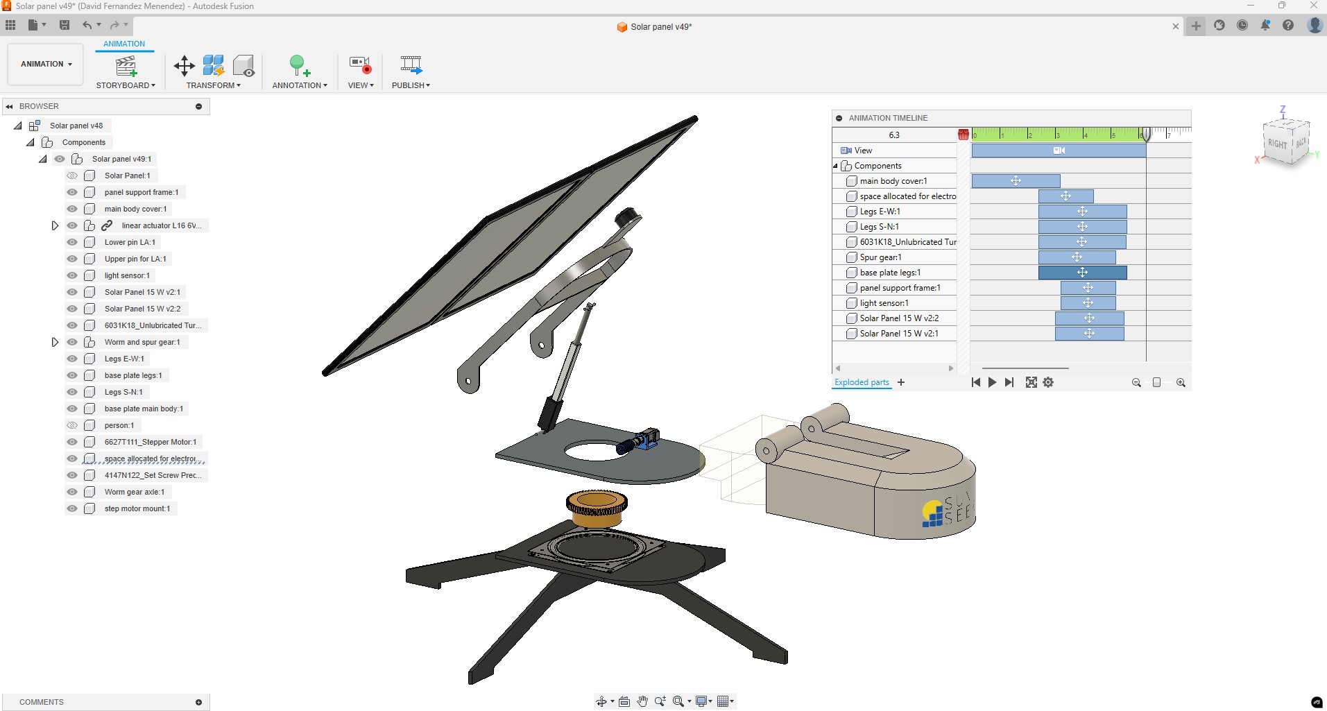
IMAGE AND VIDEO COMPRESSION
We have been reminded of the importance of resizing images to around 200KB. In terms of file sizes, it is important to remember that a Git push to the remote repository must be fewer than 10MB and that the total maximum storage available for each student in the repository is 100MB.
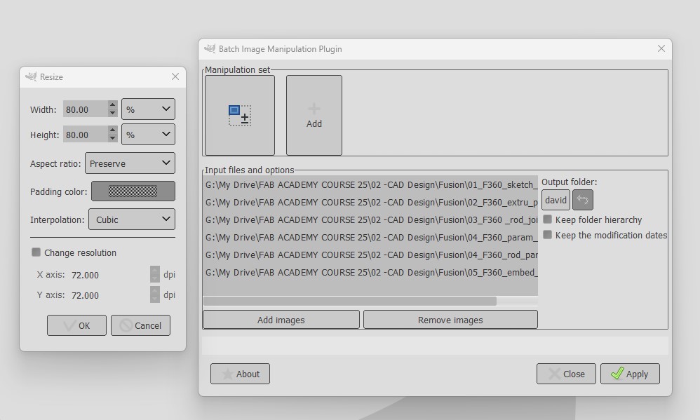
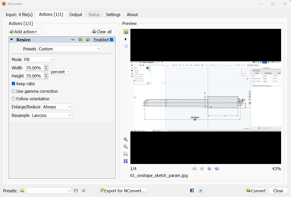
I am using .PNG when I need images with transparent background and .JPEG for the rest. For most images I am using a width of 800px, and I increase it up to 1280px when there are lots of details in the image. For the image optimization I am using GIMP with the BIMP plugin to perform batch resizing.
During the first Open Saturday session, Rico recommended using another batch converter; XnConvert which I also find useful.
To compress video, I use the open-source software FFmpeg, which operates through command lines. For installation, I followed a tutorial and received some assistance from my instructors.
I placed the FFmpeg folder on my desktop and moved the video I want to compress there as well. Using Git Bash, I located the folder path, and with the following command line, I successfully reduced the video size from 3.18 MB to 695 KB.
ffmpeg -i F360_param_design.mp4 -vcodec libx264 -crf 25 -preset medium -vf scale=-2:1080 -acodec libmp3lame -q:a 4 -ar 48000 -ac 2 output_video.mp4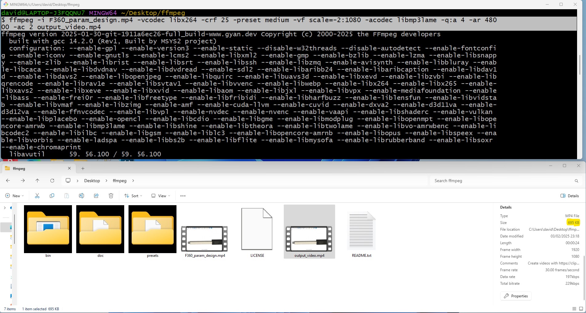
USEFUL LINKS AND RESOURCES
- XnConvert Batch image converter
- GIMP batch image resize
- Resize Images using Gimp
- HTML5 MP4 ffmpeg encoding Video compression
- Installing FFmpeg on Windows Tutorial
FILES
2D Inkscape logo design: Download link
FreeCAD 2D design: Diagram linear actuator position: Download link
ONSHAPE. View and download actuator file from this link: View and Download link
FUSION:View and download actuator file from this link: View and Download link
FreeCAD 3D design: download actuator file: Download link
FUSION:View and download final project file from this link: View and Download link
REFLECTION
This week, I had the opportunity to explore both 2D and 3D CAD software, which proved very useful in creating an initial 3D model of my project idea. I successfully incorporated both the logo design and the parametric linear actuator into the 3D model.
While I found the 2D environment beneficial, I struggled with the 3D modeling features in FreeCAD and ended up spending more time on it than I had anticipated.
Further development of the model is necessary, and I plan to contribute to the final project on a weekly basis.
Top