Week 12. Mechanical Design, Machine Design
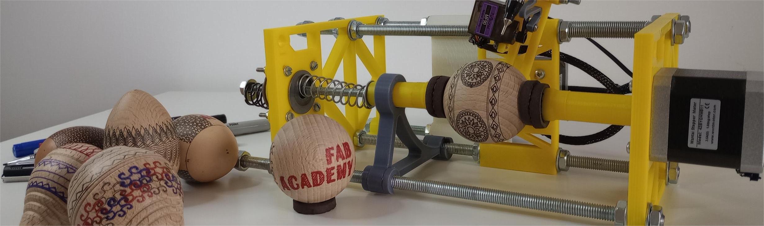
Table of Contents
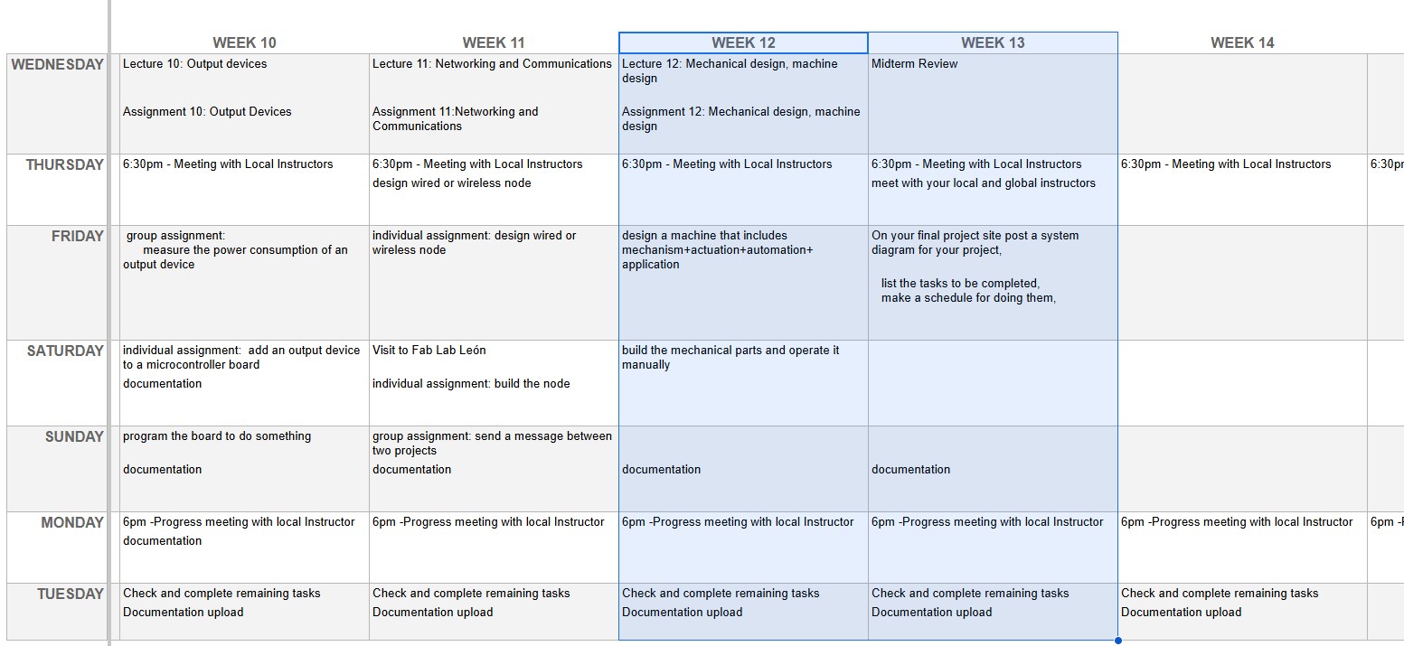
WEEKLY PLAN
Group assignment:
- Design a machine that includes mechanism + actuation + automation + application
- Build the mechanical parts and operate it manually
- Actuate and automate your machine
GROUP ASSIGNMENT
This is the link to the Fab Lab León Group Assignments page. Since I am completing the group assignment on my own I left the documentation on this page.
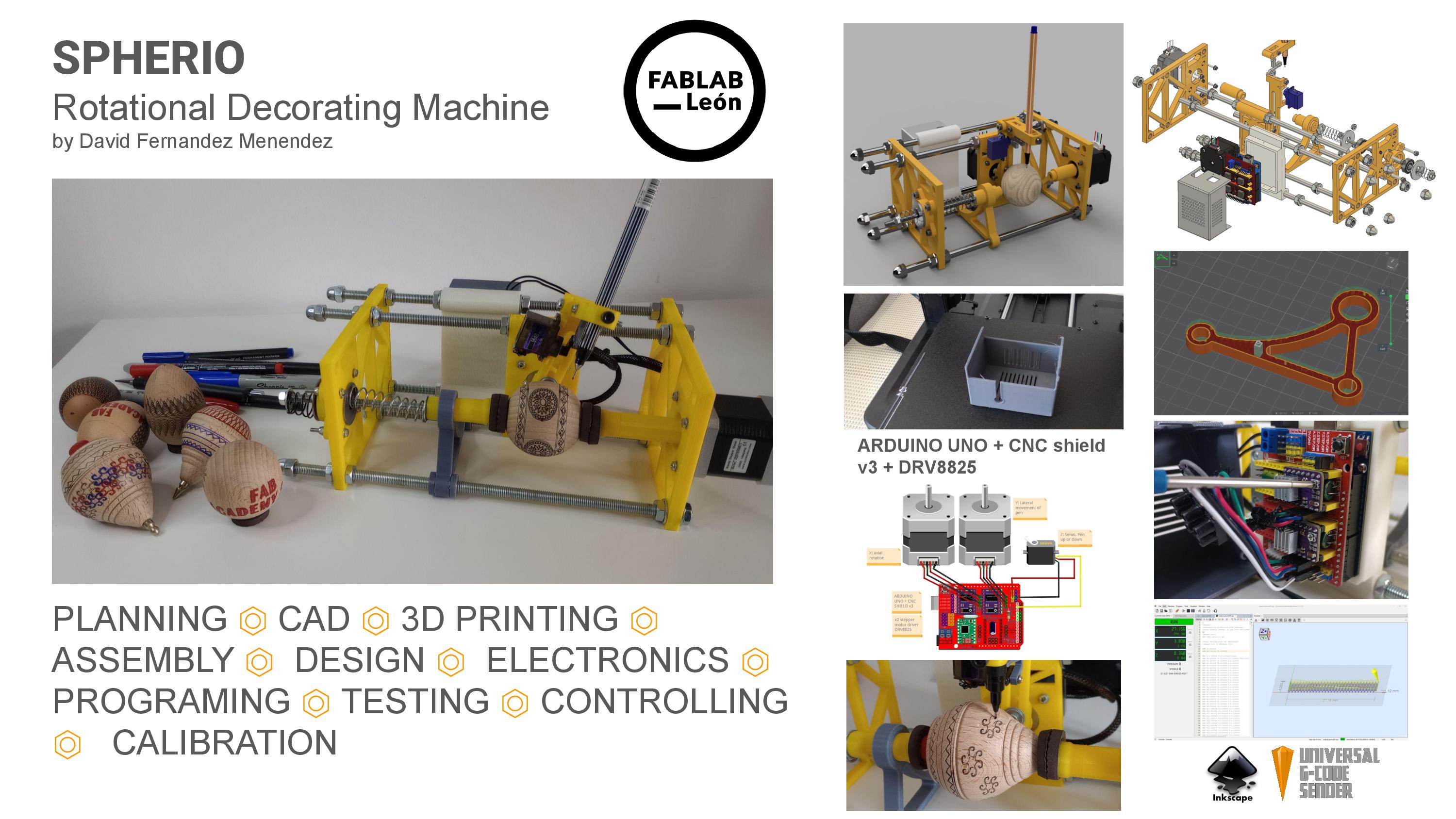
PROJECT SLIDE
PROJECT VIDEO
This week we have the opportunity to design, build, and program a machine.
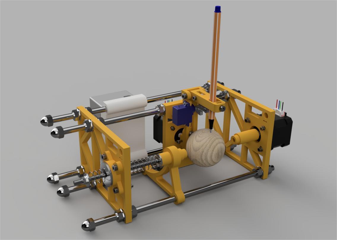
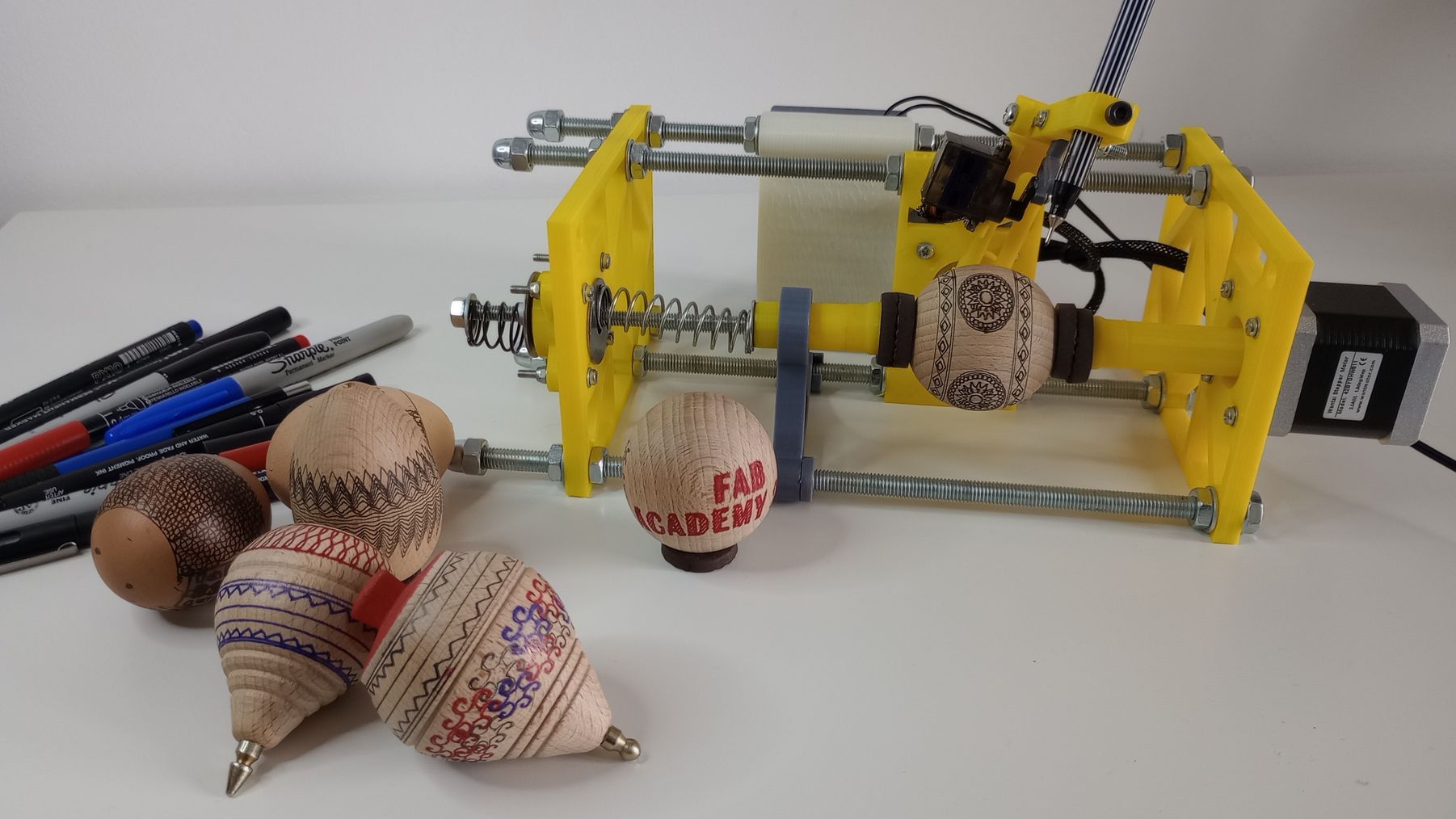
After considering some options for this week, and with the guidance of my instructors at Fab lab León, we decided to make a plotting machine to decorate spherical or egg-shaped objects.
Although I am the only student at Fab Lab León, this was a collaboration project with the staff at the Fab lab. This is how each of us contributed to the project:
|
Task |
Completed by |
|
|
1 |
3D CAD model |
David F |
|
2 |
BOM |
David F |
|
3 |
Supply of materials |
Fab Lab León |
|
4 |
3D printing and assembly |
Nuria, Adrián y Pablo |
|
5 |
Loading firmware |
Nuria, Adrián y Pablo |
|
6 |
Calibration of machine |
David F |
|
7 |
Workflow using Inkscape |
David F |
|
8 |
Testing and Troubleshooting machine |
David F |
|
9 |
Cable management and case for electronics |
David F |
|
10 |
Documentation |
everybody |
In order to complete the assignment on time, we kept the machine fairly simple, with two stepper motors, a servo motor to lift the pen, an Arduino Uno and a CNC shield.
MACHINE DESIGN
There are already many machines similar to the one I am planning to build, including the EggBot, SphereBot, and various other versions shared online by makers.
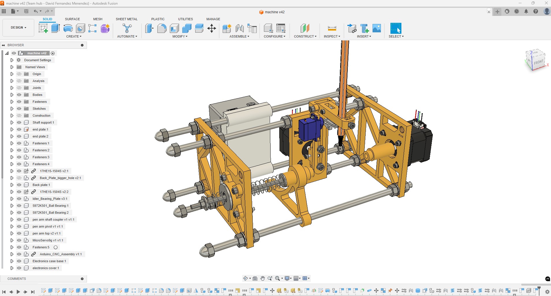
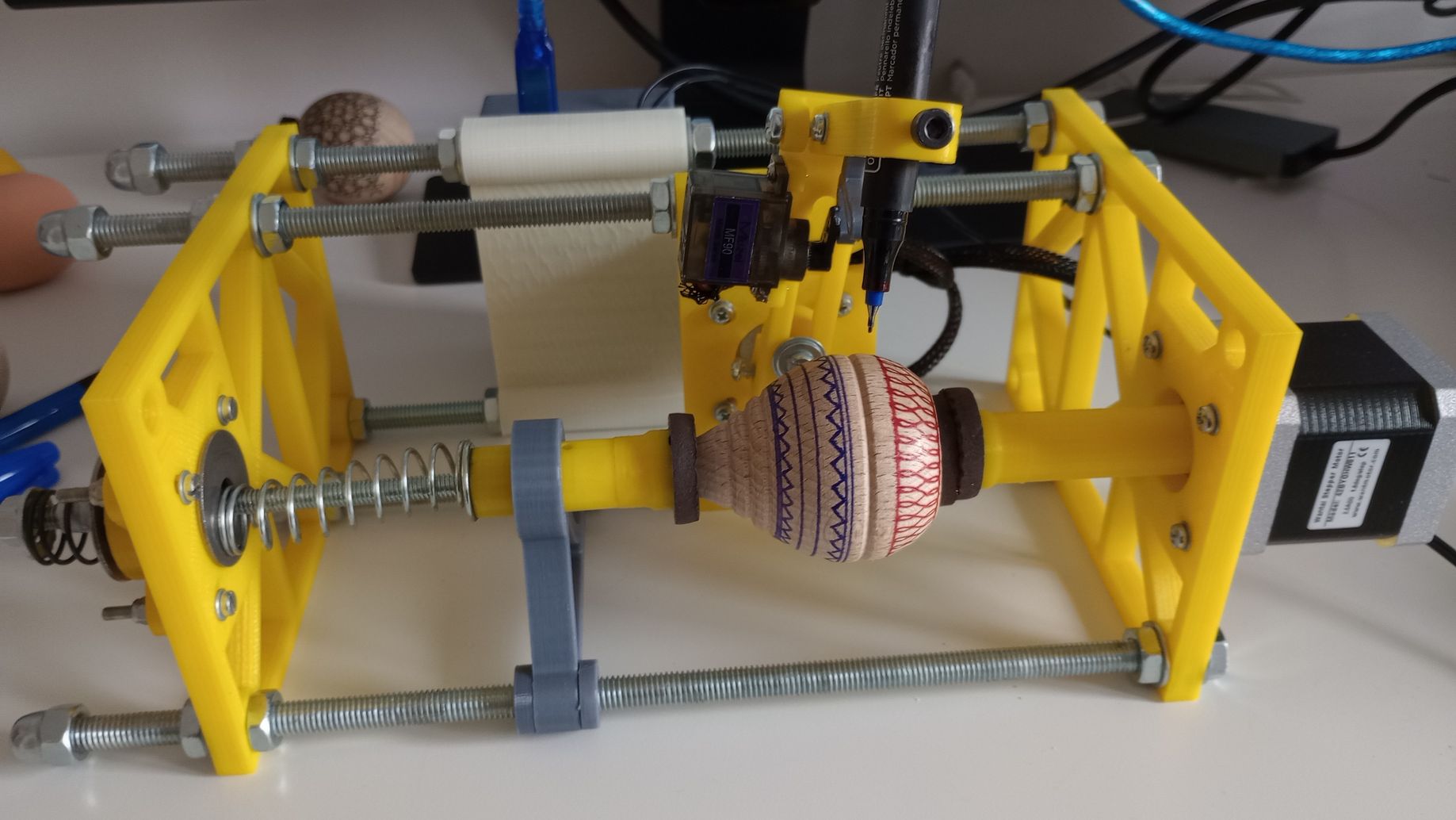
To manage my workload for this project, I am using an existing frame based on the SphereBot design created by Boris Landoni.
The frame design is fairly simple, but I am adding some enhancements, such as an enclosure for the electronics.
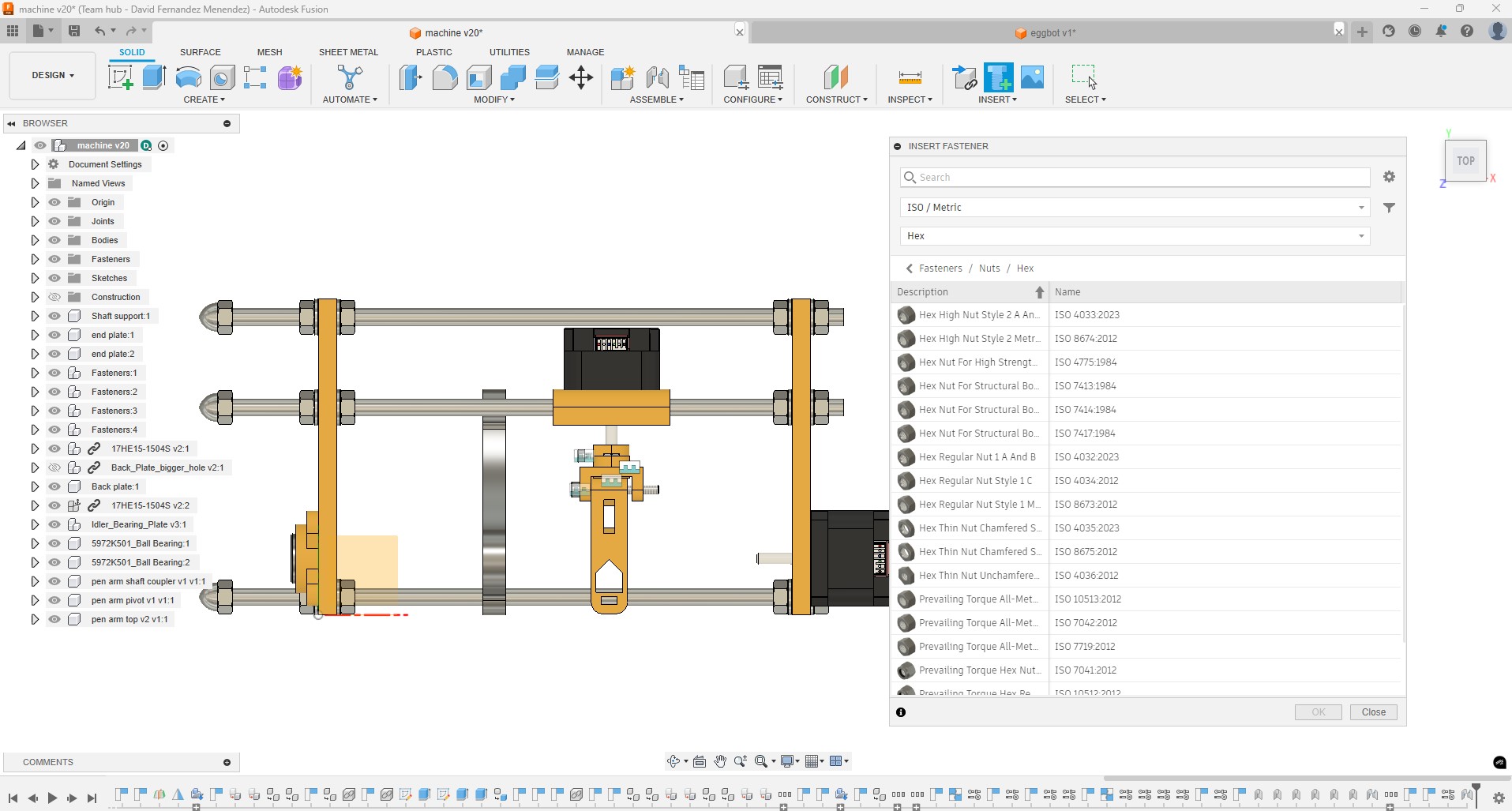
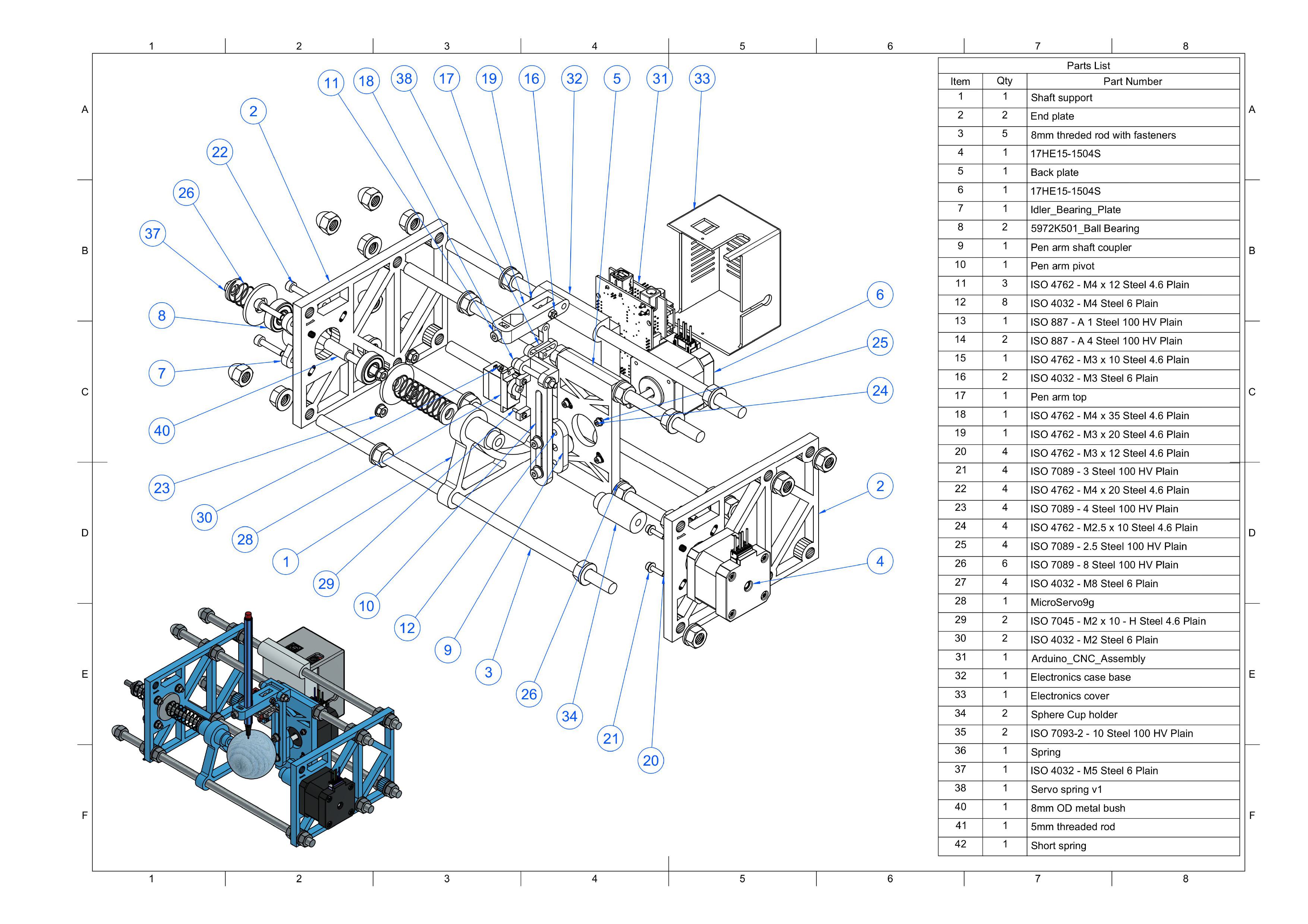
Although .stl files for the parts are available online, I have chosen to create a CAD model that will provide a comprehensive bill of materials (BOM) and allow for modifications.
I used Fusion to model the machine. The “Insert Fastener” function has been particularly useful, as there are many bolts, washers, and nuts to incorporate into the model. Once a type of fastener is selected, this functionality automatically adjusts its size to fit the hole or other existing fasteners in the model, and it even adds the four bolts of the stepper motor all at once.
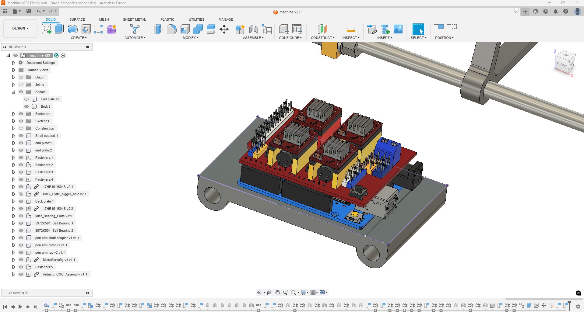
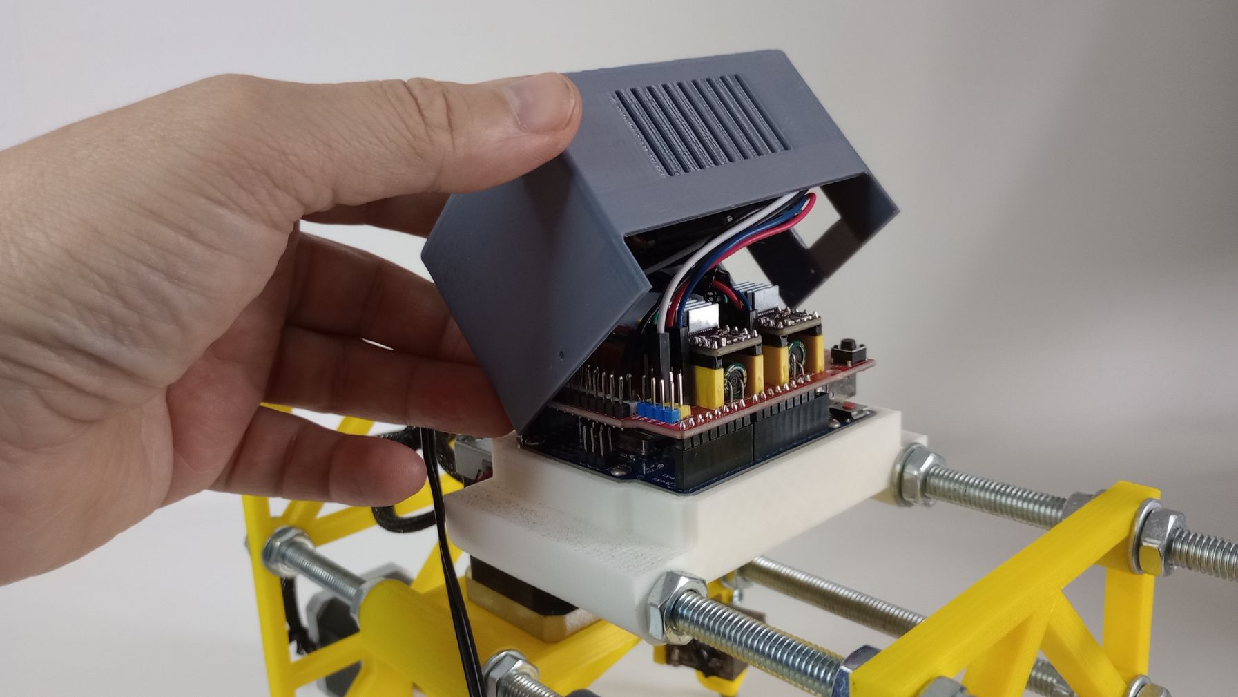
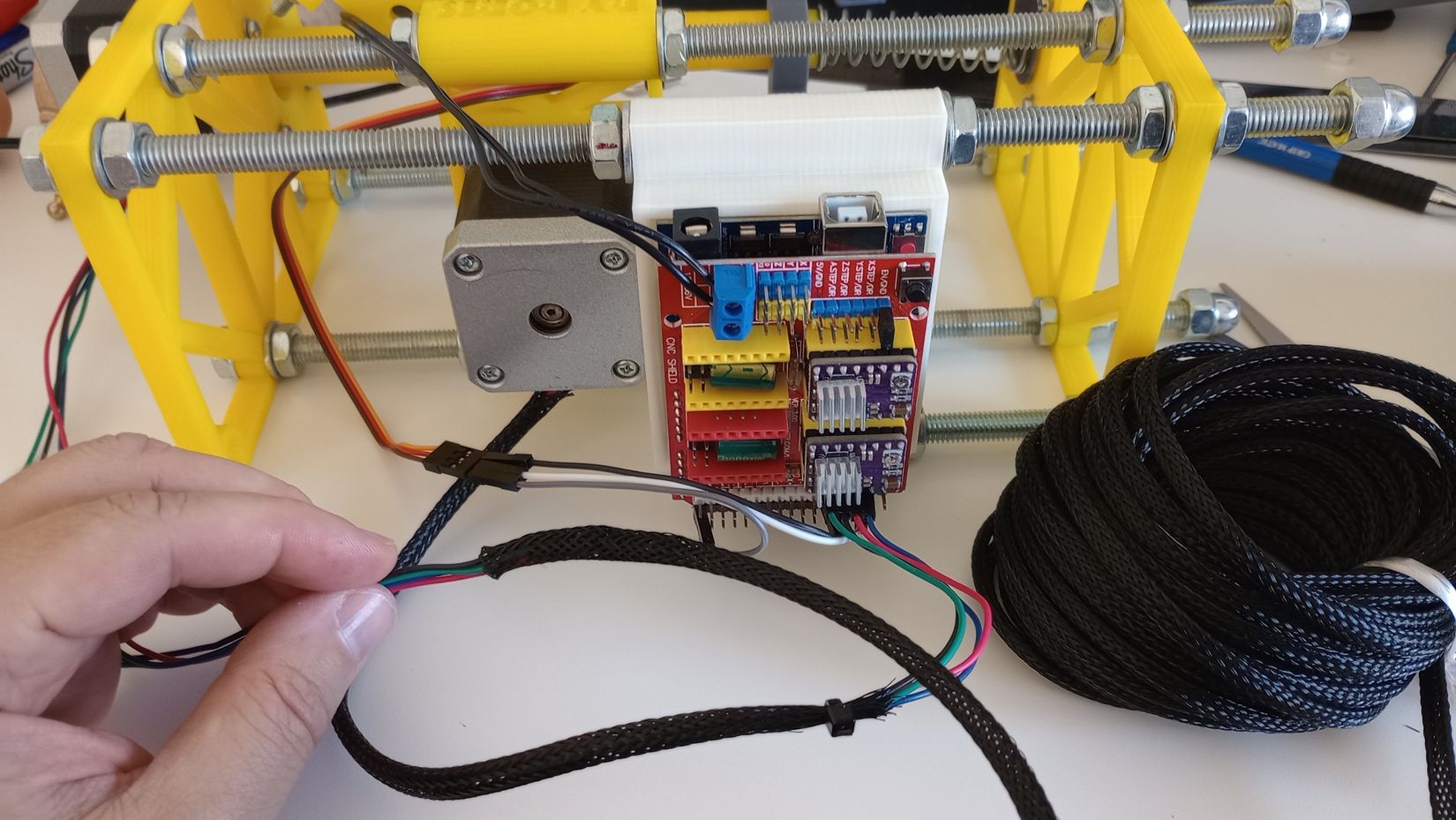
ELECTRONICS
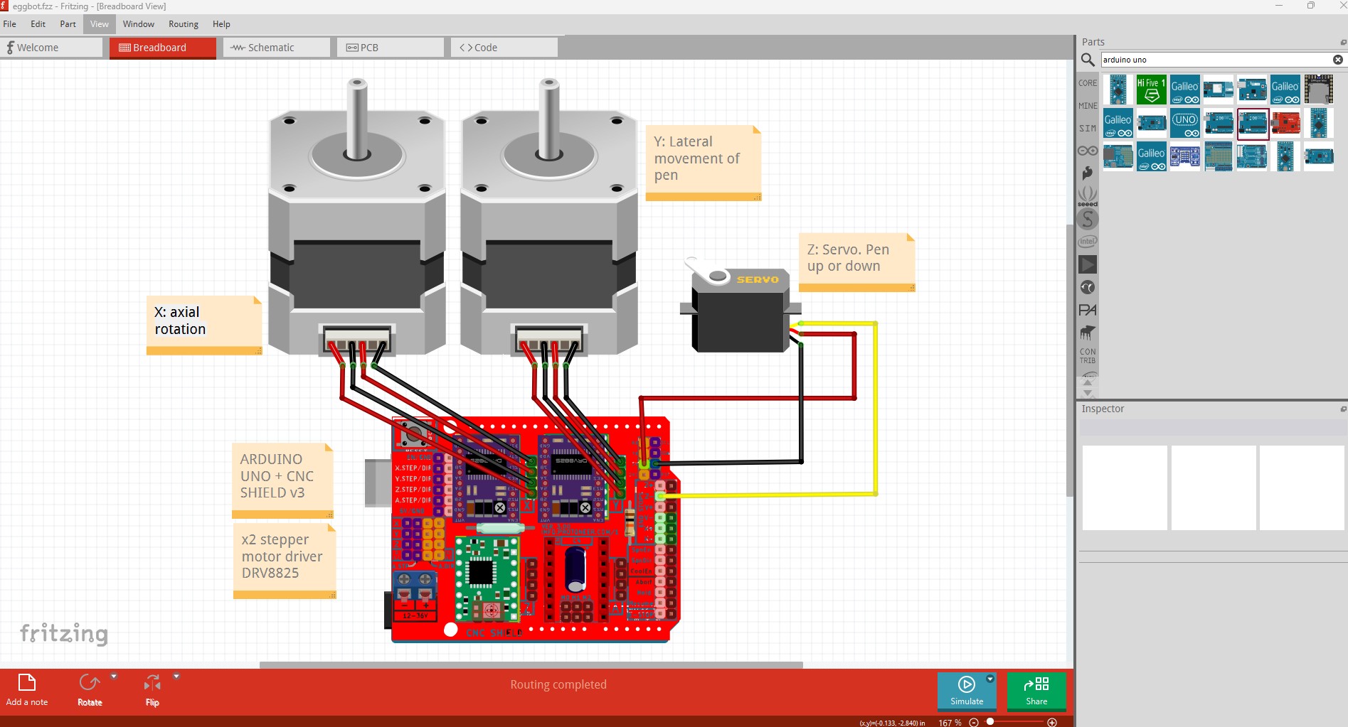
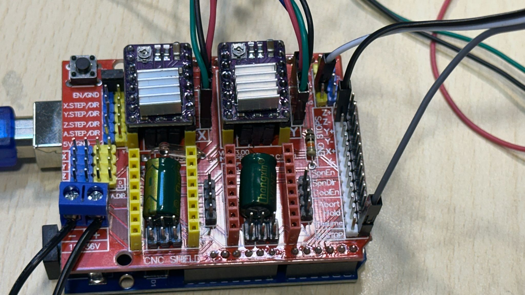
The electronic component are commonly used in machines such as DIY CNC or 3D printers:
- x1 Arduino UNO
- x1 CNC Shield V3.00
- x2 Motor drivers DRV8825
- x1 Micro servo motor MG90S
- x2 Stepper motor
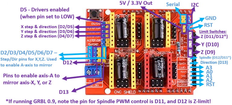
The following schematic shows how the components are wired.
The DRV8825 is a stepper motor driver commonly used to control bipolar stepper motors in robotics, 3D printers, and CNC machines.
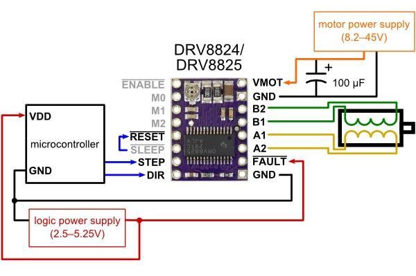
Key Features:
- Microstepping support: Up to 1/32 microstepping for smoother motion.
- Voltage range: 8.2V to 45V.
- Current control: Adjustable current limit via a potentiometer.
- Built-in protection: Over-temperature, over-current, and under-voltage lockout.
The microcontroler sends pulses to the STEP pin; each pulse moves the motor one step (or microstep). The DIR pin sets the direction of rotation.
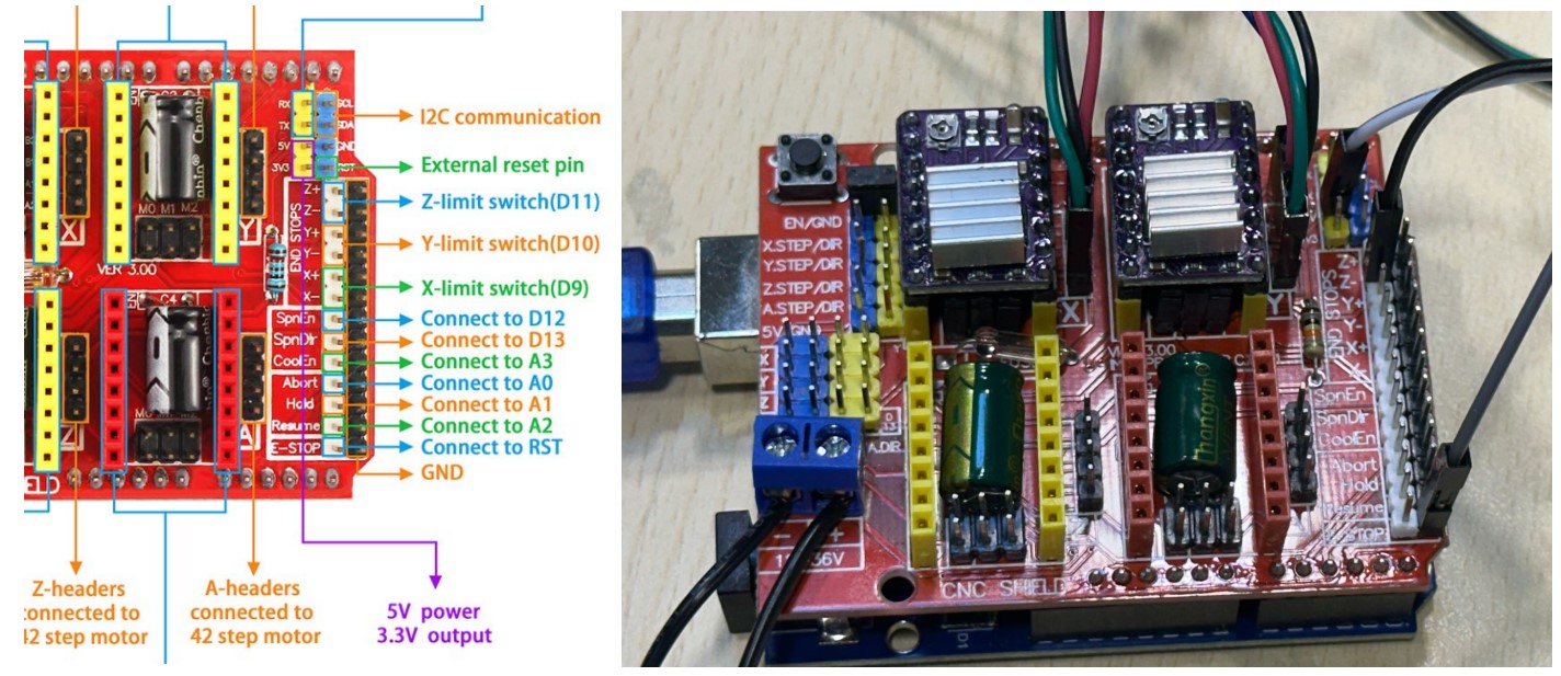
The CNC Shield V3 is an expansion board designed to fit on top of an Arduino Uno. It’s mainly used for controlling CNC machines, laser cutters, 3D printers, and engraving machines using stepper motors.
FIRMWARE
To control the machine I am using GRBL, an open-source firmware that runs on an Arduino Uno and turns it into a CNC motion controller. It interprets G-code commands and controls stepper motors to move the machine.
Installing /GRBL on Arduino
The steps I followed to install GRBL in the Arduino Uno board are mainly the ones explained on these websites:
Here is a summary of the steps I followed:
1. Download and Add GRBL as a Library
Download the GRBL source code as a .zip file from https://github.com/gnea/grbl
For this machine I have to change homing cycle from 3-axis machine to 2-axis (disabling Z-axis). In the grbl folder, open config.h and find the following bit of code:

The code needs to be modified as shown:

This removes the step in which we home the Z-axis, and we now only home the X-axis and the Y-axis. Next, compress the modified grbl as grbl.zip
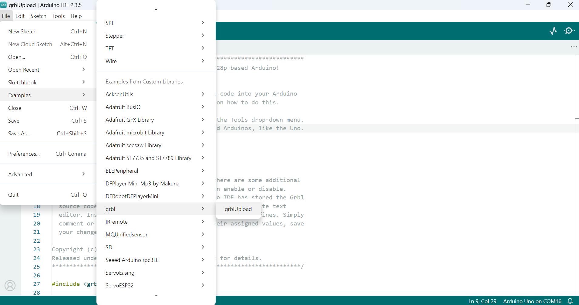
In Arduino IDE, navigate to Sketch > Include Library > Add .ZIP Library
Select the modified grbl.zip file to add it as a library.
2. Upload GRBL to the Arduino Uno
Open Arduino IDE and connect the Arduino Uno to a computer via USB. Select the correct board and port under Tools > Board and Tools > Port.
Click the Upload button to flash GRBL onto your Arduino Uno
Once done, you can type $$ in the serial monitor to view the current GRBL settings.
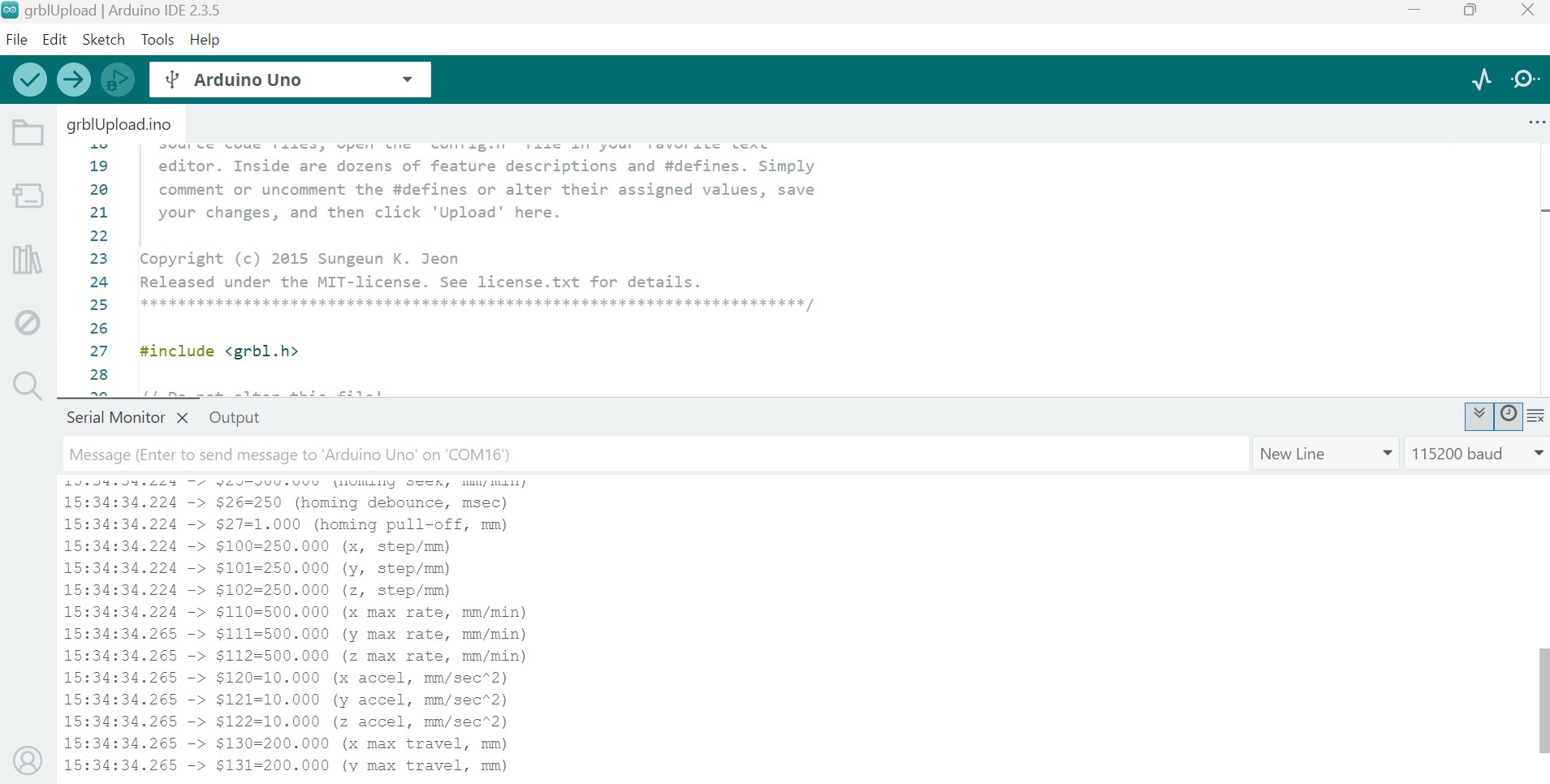
Settings like steps per millimeter ($100, $101, $102), maximum rates ($110, $111, $112), and acceleration ($120, $121, $122) can be modified. To change a setting, type the command (e.g., $100=250.000) and press Enter.
For now I am not making any changes on these settings.
3. Adding the Pen servo feature
This machine works a bit different than a CNC. The servo that lifts the pen needs a up or down position, the problem is that GRBL is not designed to work with servo motors.
The work around to solve this, is explained in this tutorial for an eggbot. Here are the steps:
- Download the modified GRBL filesfrom this GitHub repository: https://github.com/bdring/Grbl_Pen_Servo
- Replace the original GRBL libraryin the Arduino libraries folder with the downloaded one.This will overwrite some files and add servo support.
- Once installed, the firmware will handle pen control automatically:
- If the Z-axis value in the G-code is above 0, the servo moves the pen up.
- If the Z-axis is 0 or below, the servo moves the pen down.
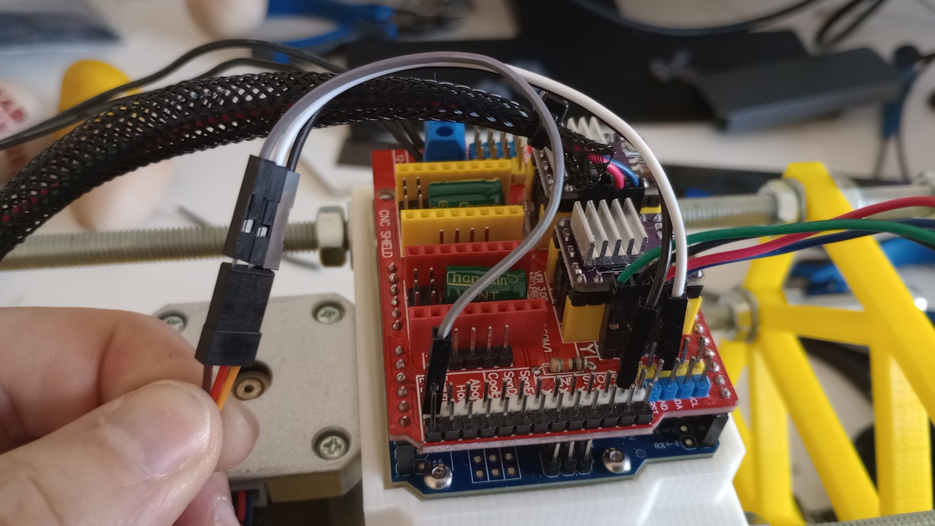
The signal cable of the servo will be connected to the D11 pin on the shield board.
 Top
Top
MACHINE SETUP
When running GRBL on the Arduino UNO, commands must be sent from an external device to control it. The most common method is connecting the UNO to a computer via USB and using controller software like UGS (Universal G-code Sender) to send the commands.
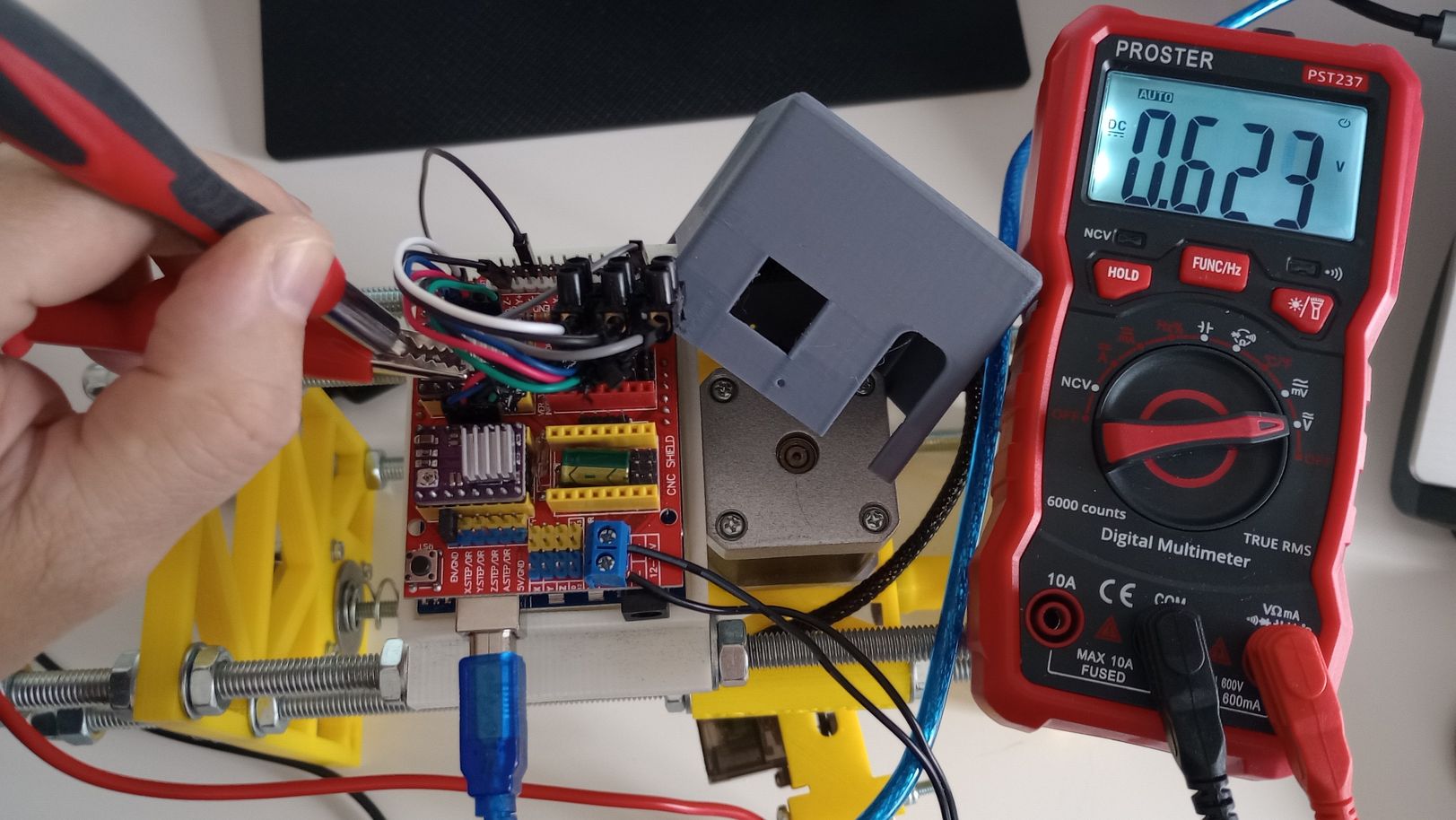
Current Limit (Reference Voltage) Adjustment for Stepper Driver
In order to protect the motor and the driver is necessary to start by adjusting the Reference voltage. This is done by a turning a potentiometer on the drivers.
Confirm the rated current per phase for the motor (in this case 1.25Amps).
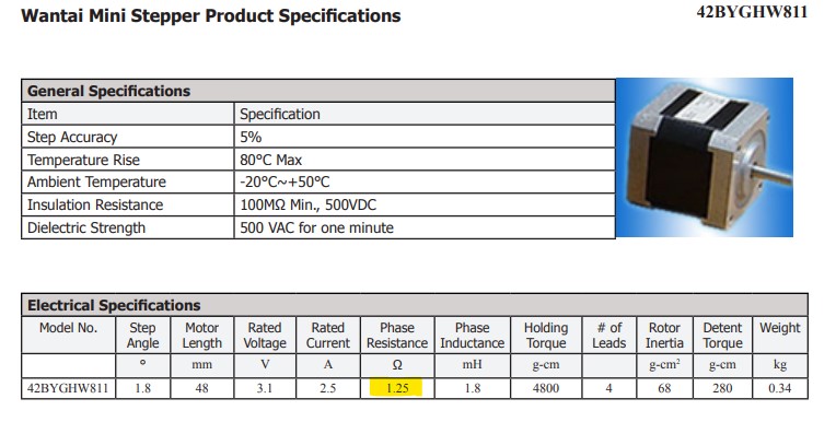
Divide this number by 2.5ohms. (The actual number will depend on the value of an internal resistance within the module (varies by manufacturer and based on tolerance of the actual resistor used)).
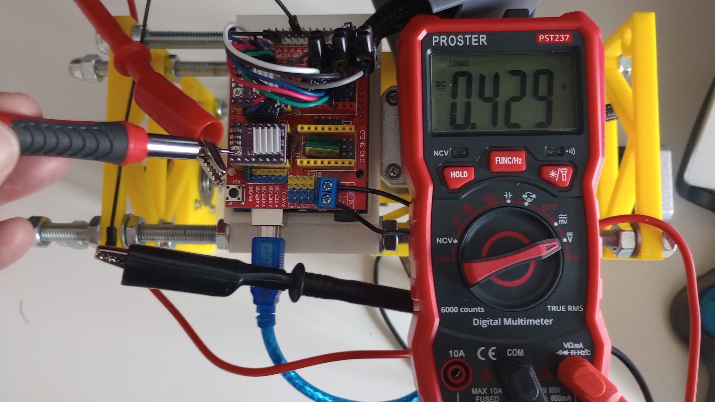
The resulting number 1.25A / 2.5Ω = 0.5V is the reference voltage (VREF).
I use a multimeter to measure the Vref in the potentiometer and adjust it accordingly.
Connecting Universal Gcode Sender (UGS) to the machine
With the machine connected to power and to the computer via USB. Open USB Sender and go to “Machine” -> “Setup wizard…”.
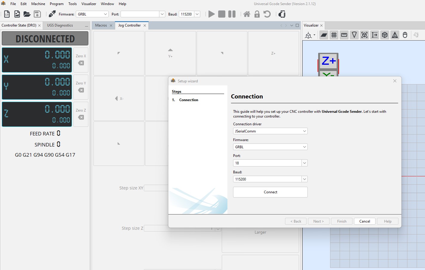
After the Setup is completed I click on “Connect”.
Using the jog controller in UGS I can now check how the motors respond.
Generating Gcode from SVG file
Although gcode can be directly written on UGS and sent to the machine, it is more practical to create drawings in .svg format, which can then be converted into gcode.
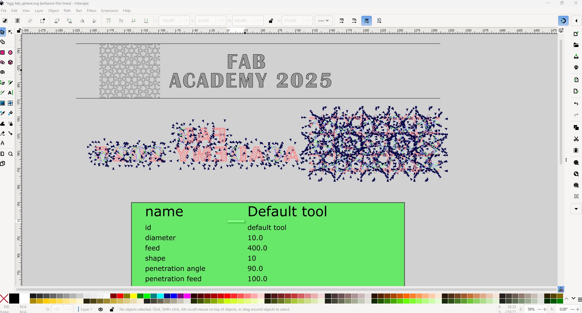
For graphic design and conversion to G-code, I use Inkscape.
To decorate any object, I start by determining the dimensions of area. I do this by using the jog controller on UGS.
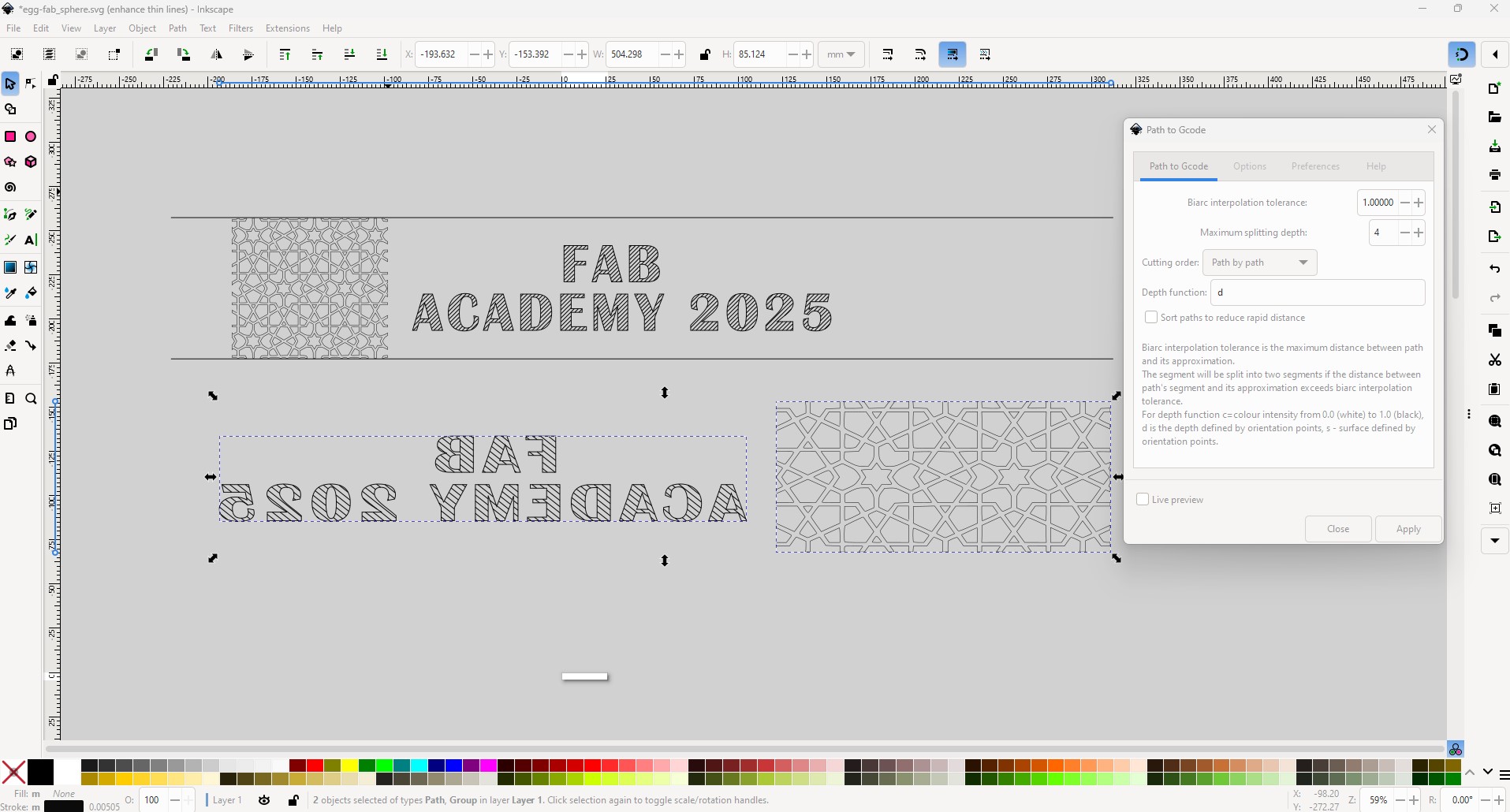
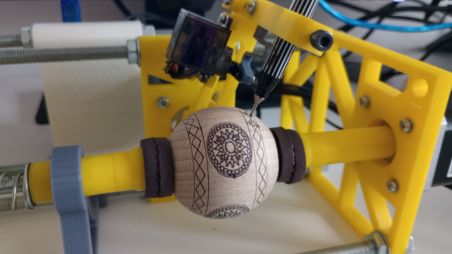
For the sphere shown, the dimensions are limited to Y = 4.15 mm and X = 25 mm. Therefore, any design must fit within these specifications. Additionally, if text is included in the design, it needs to be mirrored before plotting.
In Inkscape, there is an extension that allows you to generate code from your design. First, I select all the objects and convert them to paths by navigating to Path > Object to Path. Then, go to Extensions > Gcodetools > Path to Gcode to generate a .ngc file, which contains all the necessary commands to plot the design.
I open the .ngc file in UGS and I zero the pen in the X and Y positions.
Before sending the file I use the function in the visualizer to move the machine around the edge of the design to ensure the origin is set up properly.
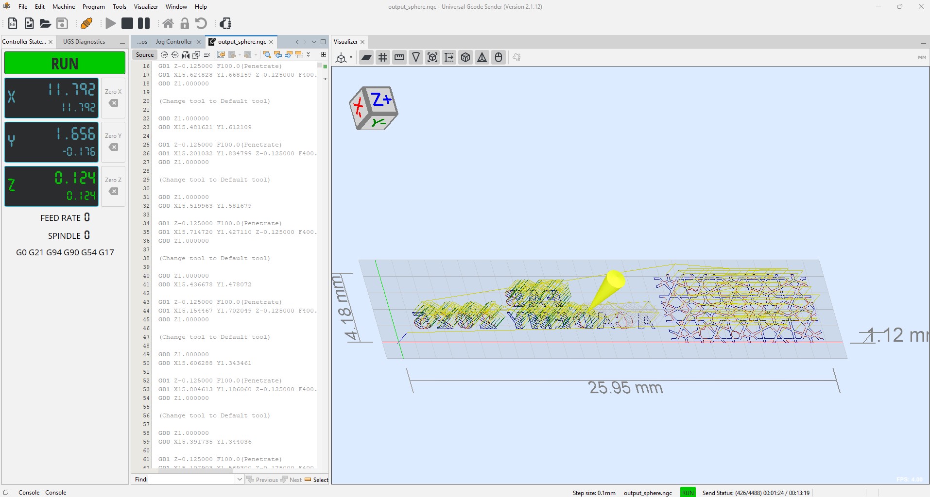
The design is now ready to be sent. The plotting process can be paused to switch to a different colored pen. Once I have a clear workflow, I can run additional tests with various shapes and designs
TROUBLESHOOTING THE MACHINE
During the project, I encountered a few issues that I would like to explain.
Initially, the motors did not provide enough torque to move he object that needed to be plotted. To resolve this, I adjusted the potentiometer on the motor drivers.
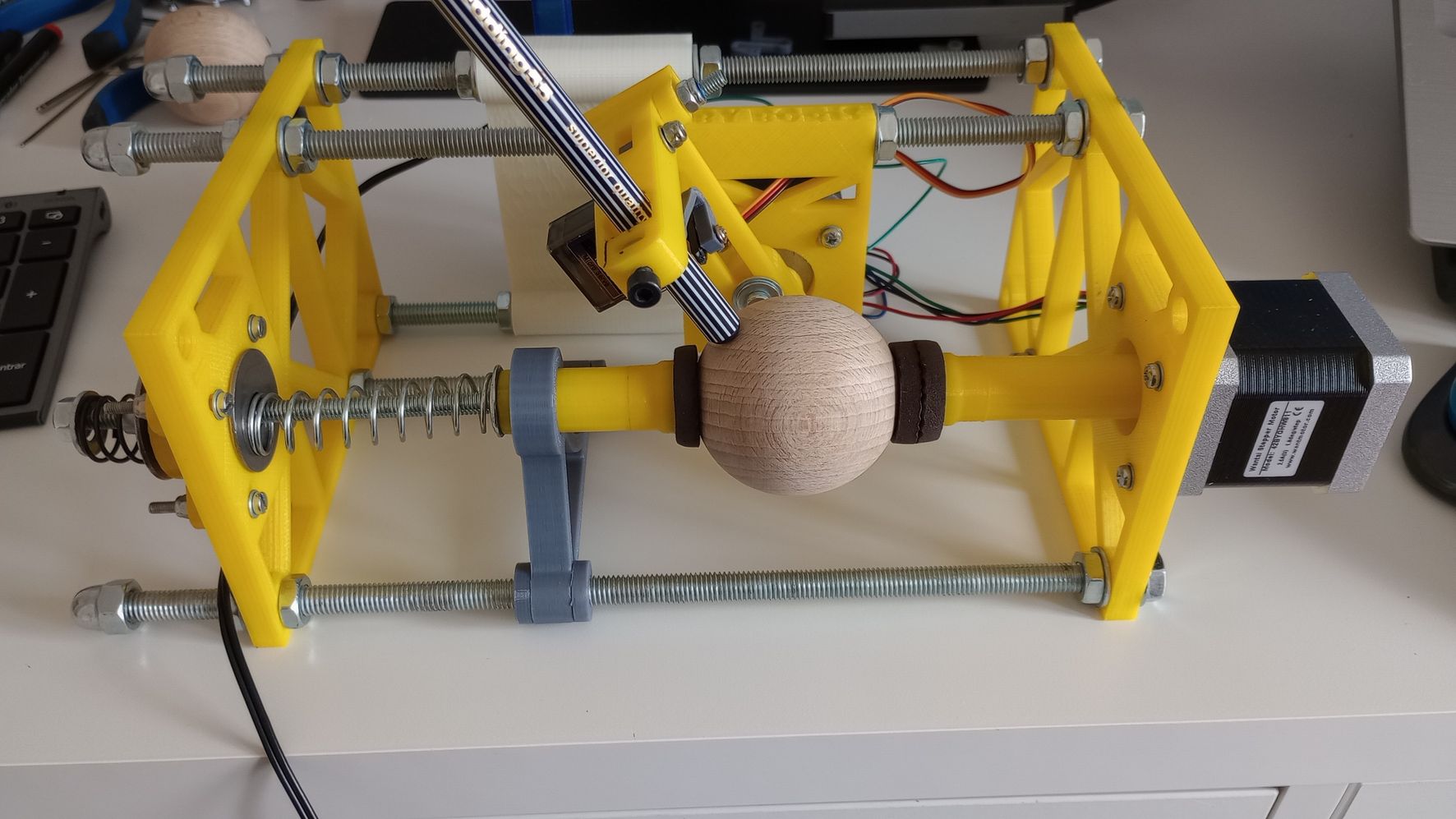
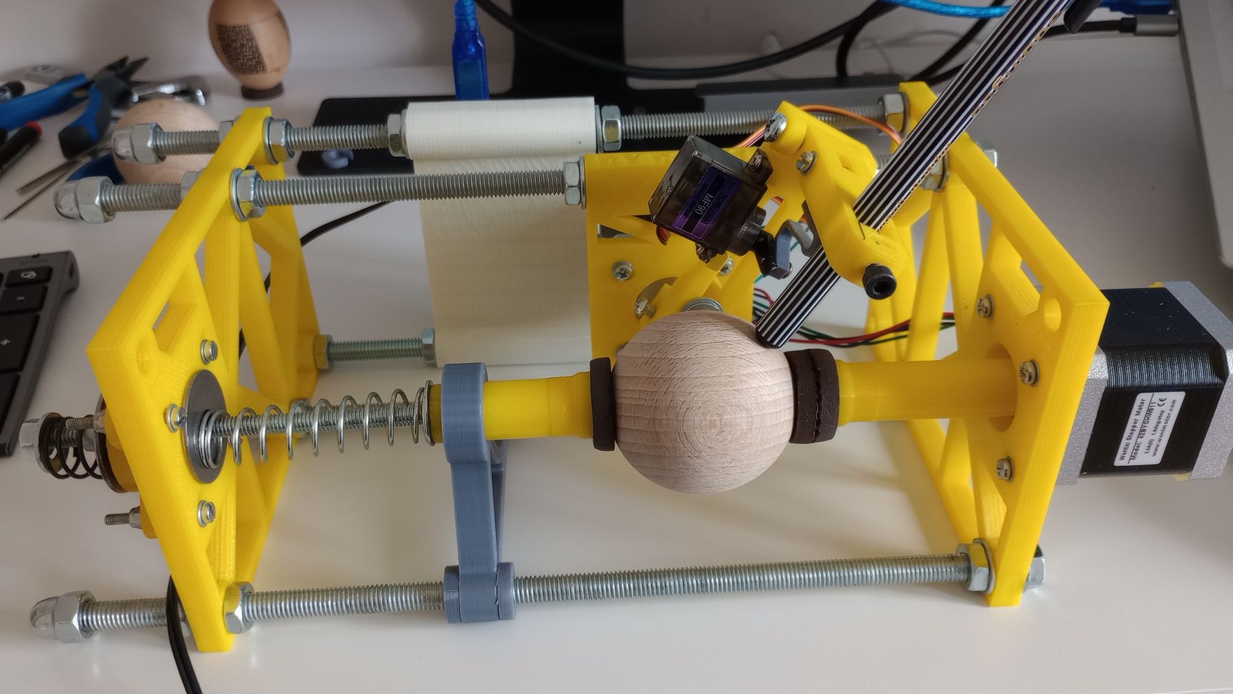
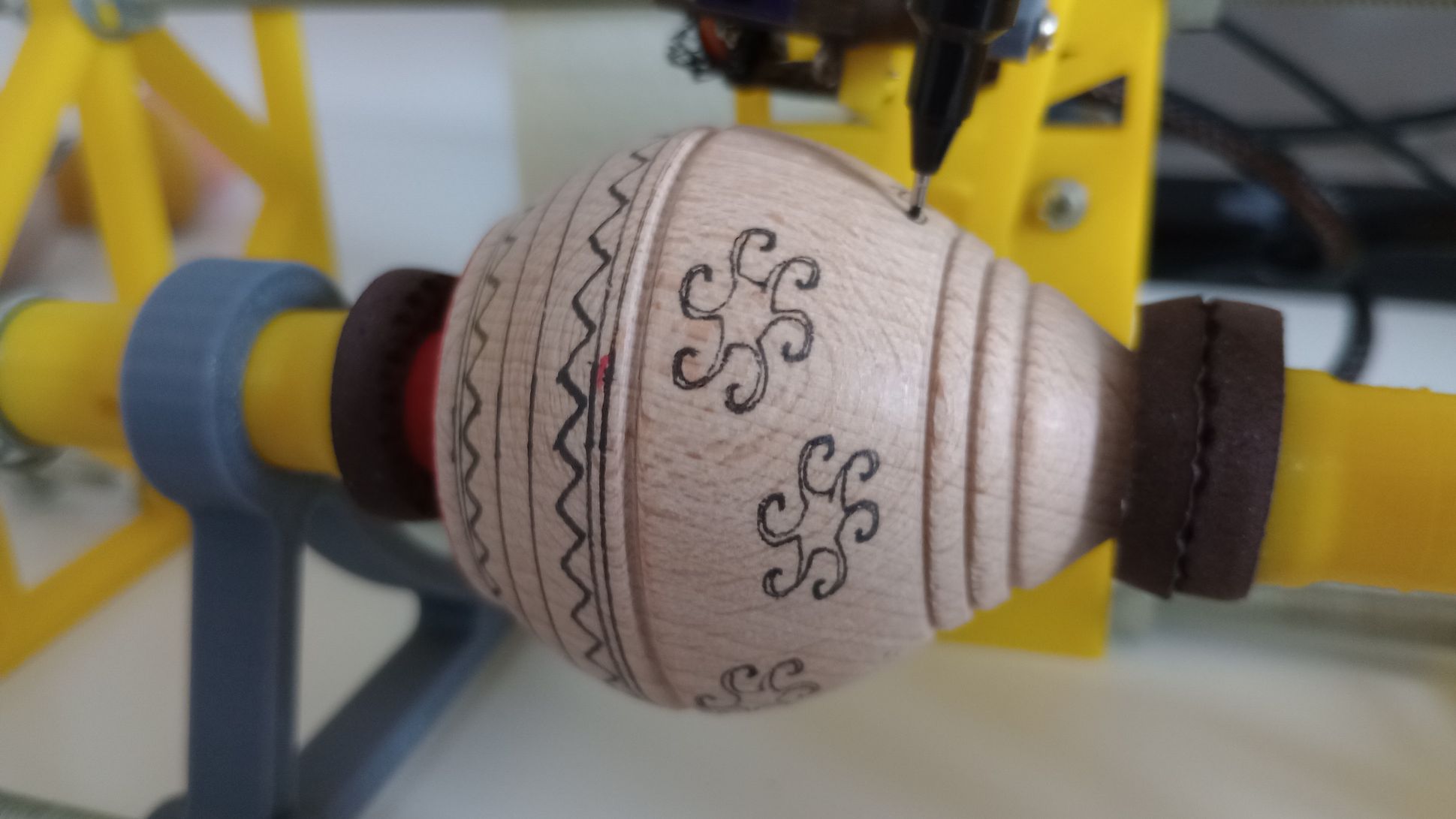
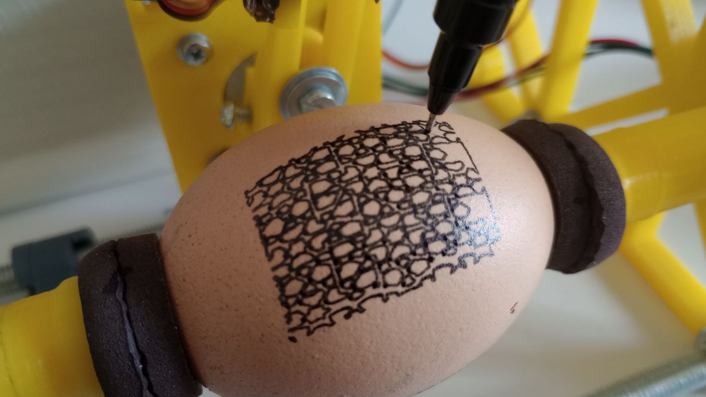
I experimented with various egg-shaped and spherical objects, including styrofoam eggs, wooden spheres, wooden spinning tops, and real eggs. The styrofoam eggs were not successful because the material was too soft, causing the pen to get stuck.
I also struggled with keeping the objects stable while plotting. To address this, I adjusted the tension of the springs, moved the frames closer together, and added a support piece for the axle on the left side. This additional support significantly helped in keeping the axle straight.
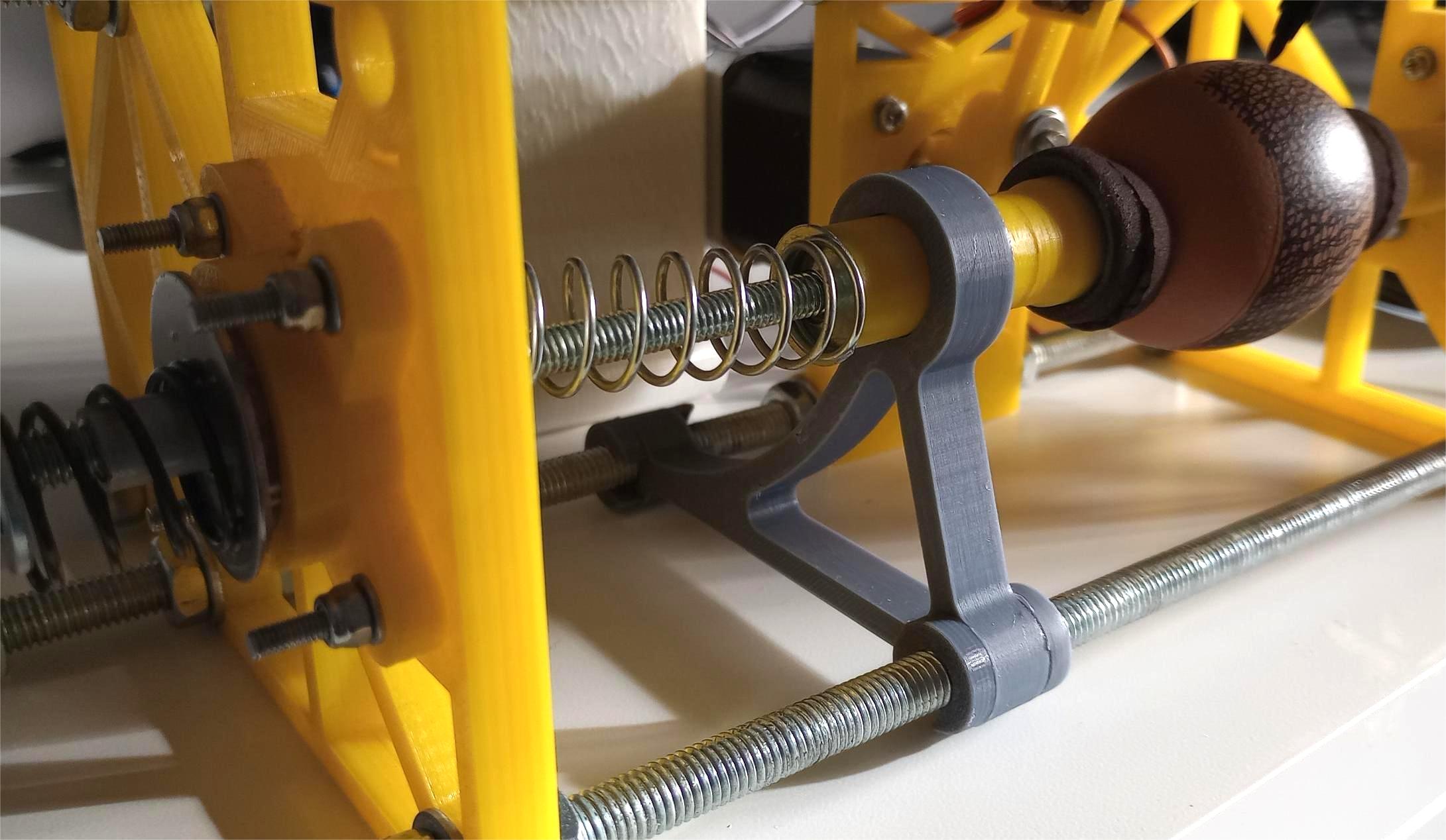
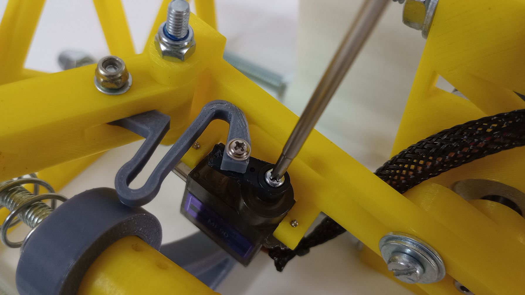
I added sticky felt pads, typically used on furniture, to enhance grip and prevent the object from sliding when the horizontal axis is spinning. The servo spring that controls the upper arm broke, so I printed a new one using PETG. This material is stronger and more flexible than the original made with PLA.
As a final touch to improve the machine, I also made a case and tidied up the cables using braided sleeves.
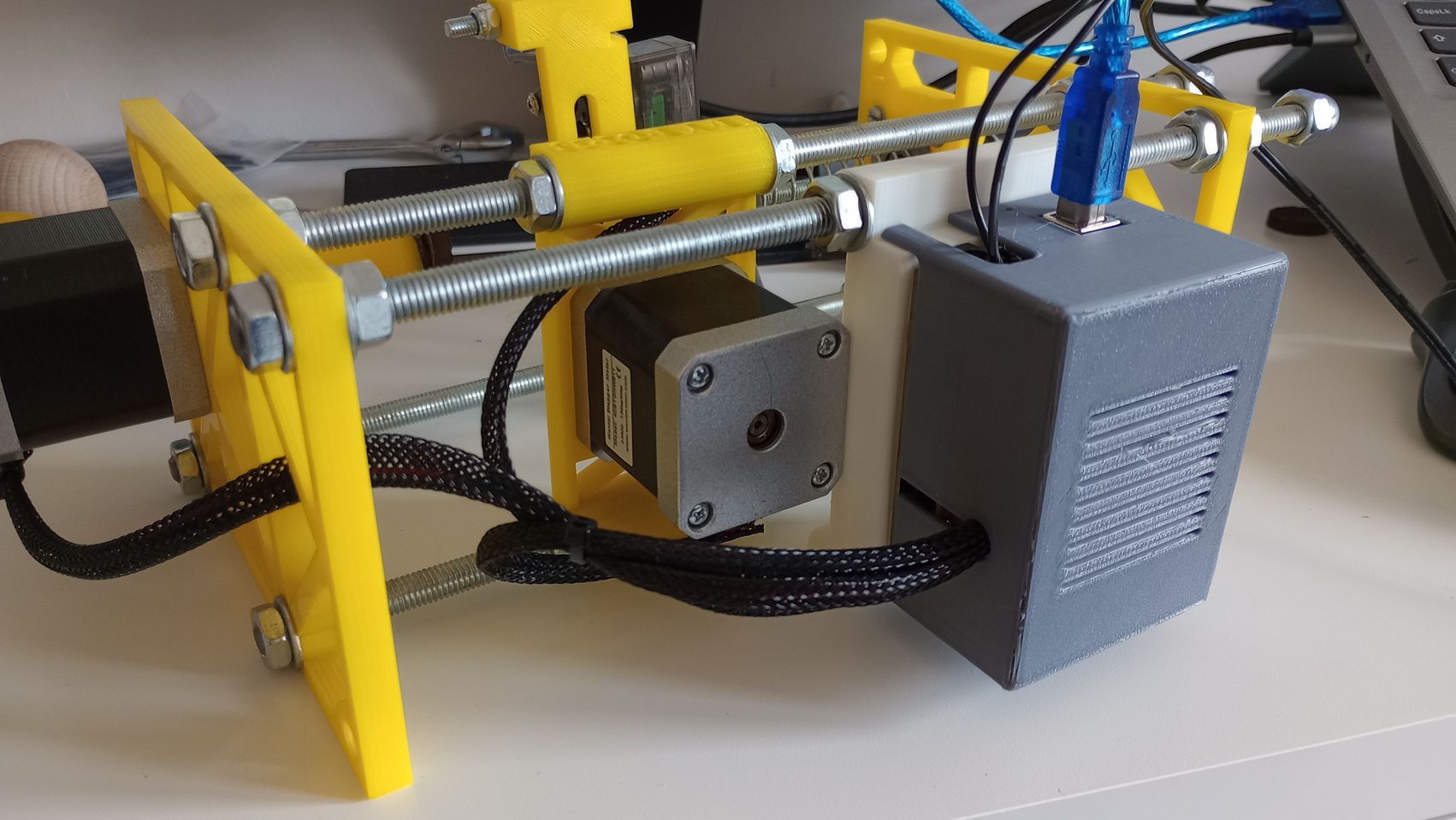
THE MACHINE AT WORK
Now that all those issues have been resolved, I can finally achieve some good results.
USEFUL LINKS AND RESOURCES
- SphereBot project by Boris Landoni
- EggBot
- Arduino CNC Shield V3 - Protoneer.co.nz
- GRBL with Arduino CNC Shield – Complete Guide
- How to Setup GRBL & Control CNC Machine with Arduino
- DIY Arduino Based EggBot
- Grbl with Pen Servo Feature
FILES
Fusion CAD model of machine: Spherio_machine_CAD.f3z
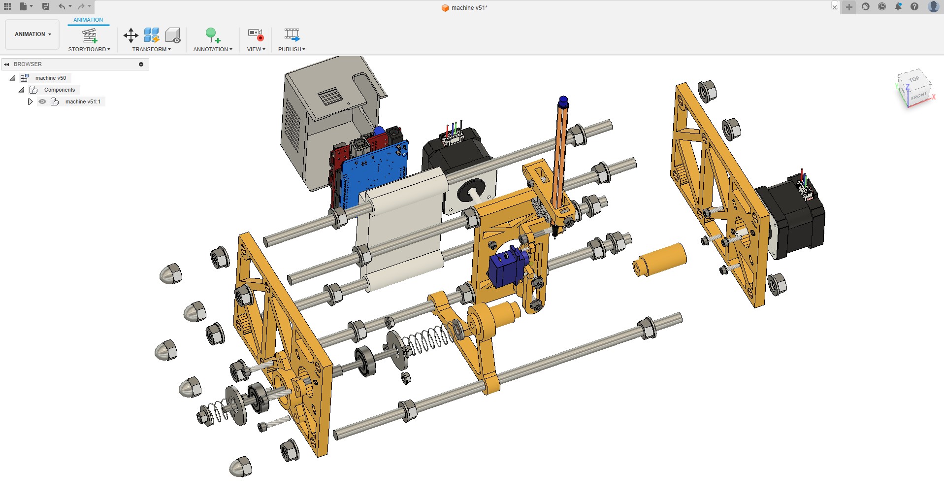
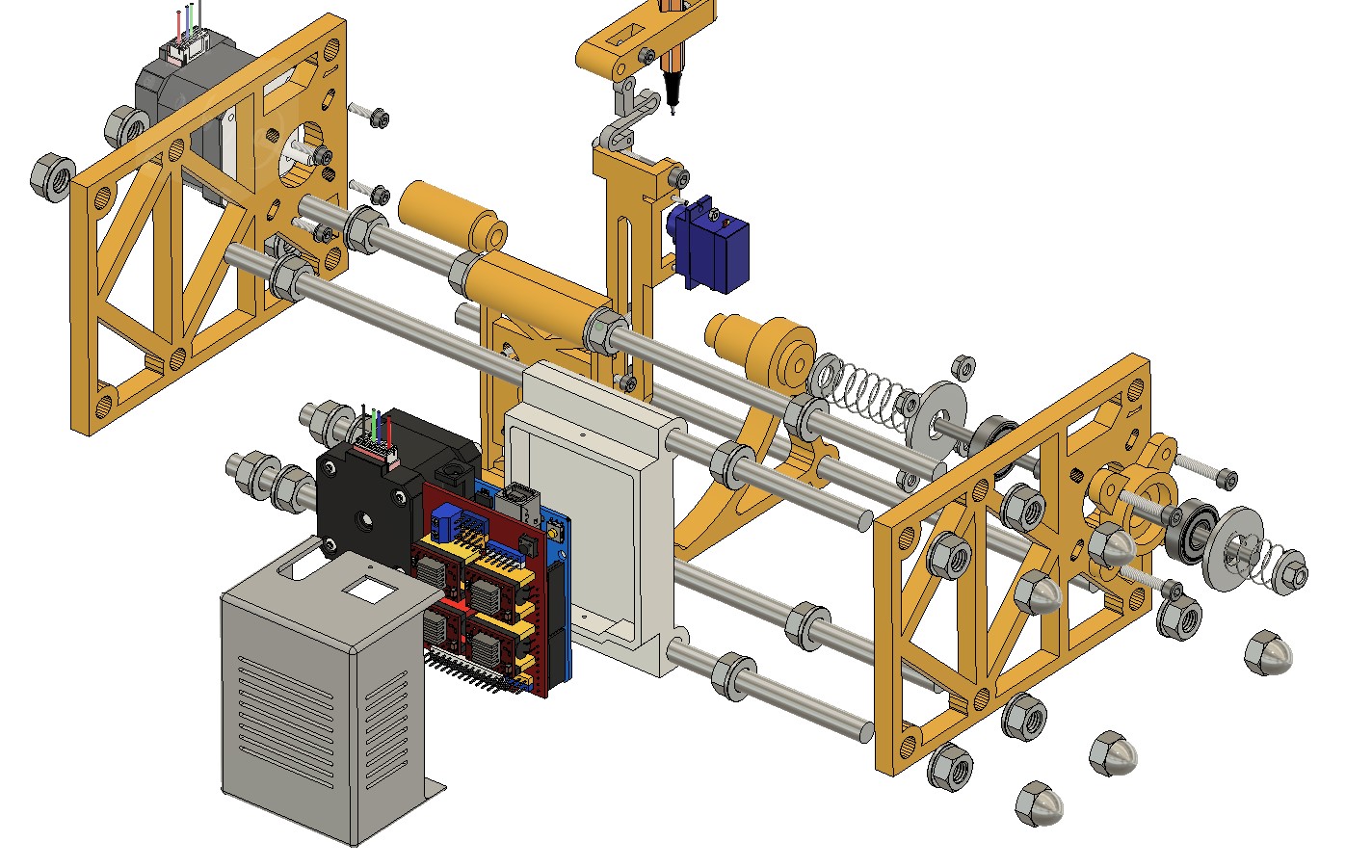
Exploded view and BOM: Machine Drawing exploded view and BOM.pdf
Electronics wiring (Fritzing): machine_electronics_wiring.fzz
Top