Week 07. Computer-Controlled Cutting
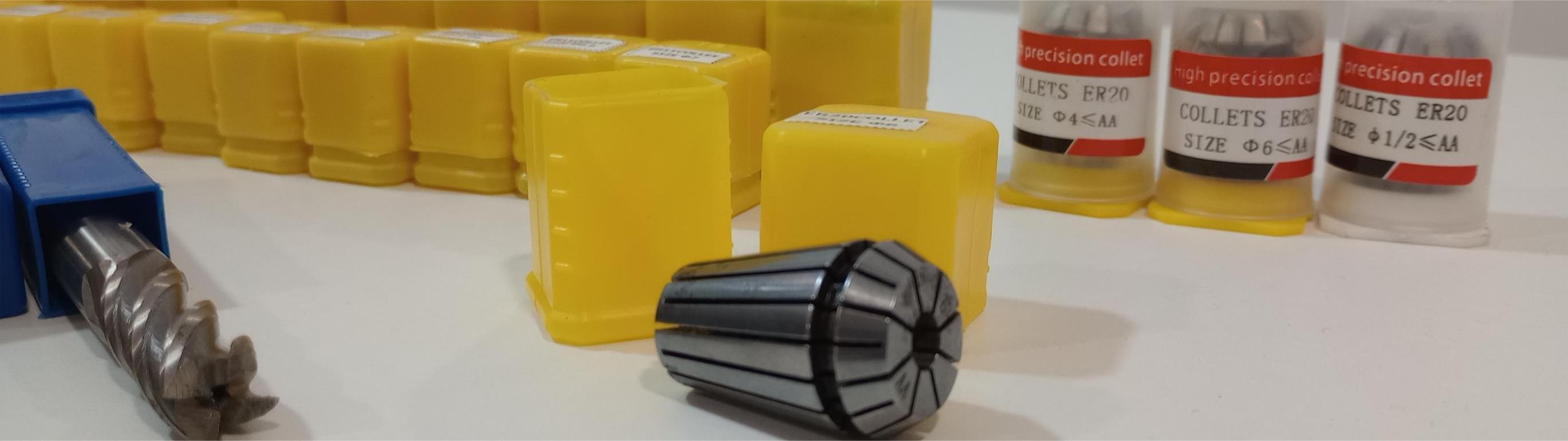
Table of Contents
- WEEKLY PLAN
- GROUP ASSIGNMENT: CNC
- INDIVIDUAL ASSIGNMENT: DESIGN FOR CNC
- USEFUL LINKS AND RESOURCES
- FILES
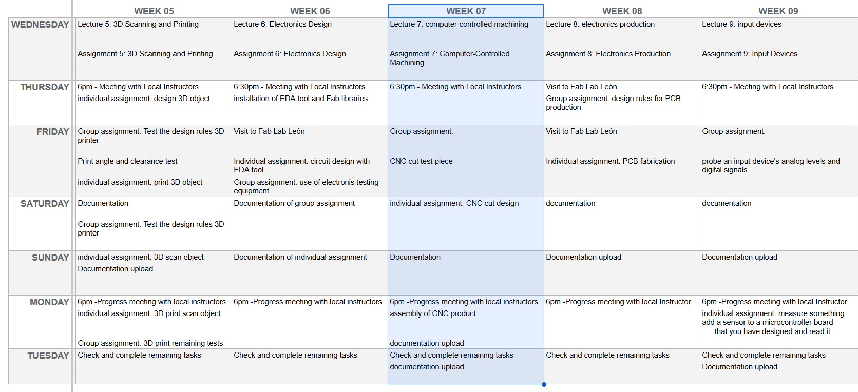
WEEKLY PLAN
Group assignment:
- Do the lab's safety training
- Test runout, alignment, fixturing, speeds, feeds, materials, and toolpaths for your machine.
Individual assignment:
- make (design+mill+assemble) something big (meter-scale)
GROUP ASSIGNMENT:CNC
This is the link to the Fab Lab León Group Assignments page. Since I am completing the group assignment on my own I left the documentation on this page.
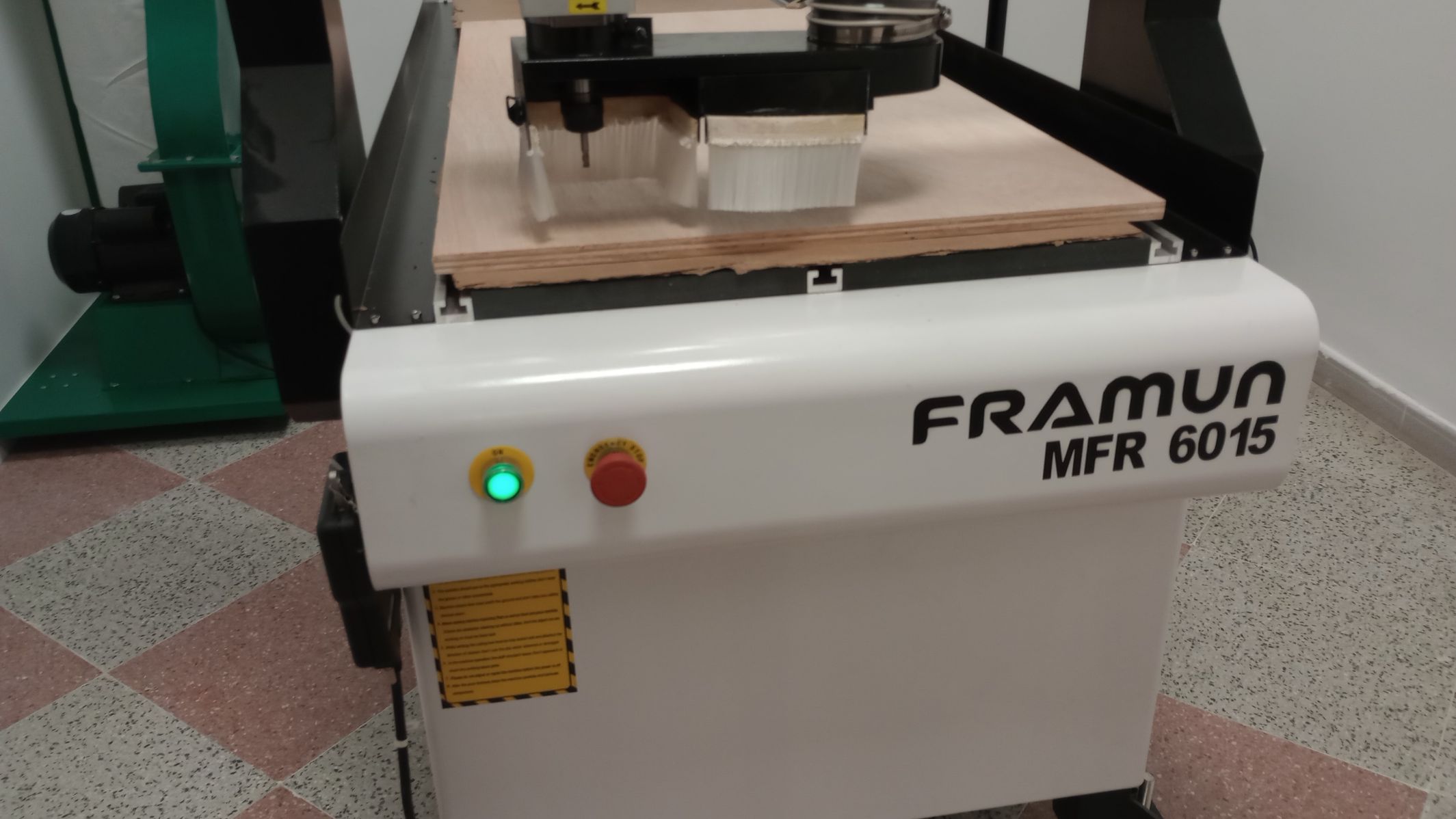
CNC PARTS AND TECHNICAL SPECS
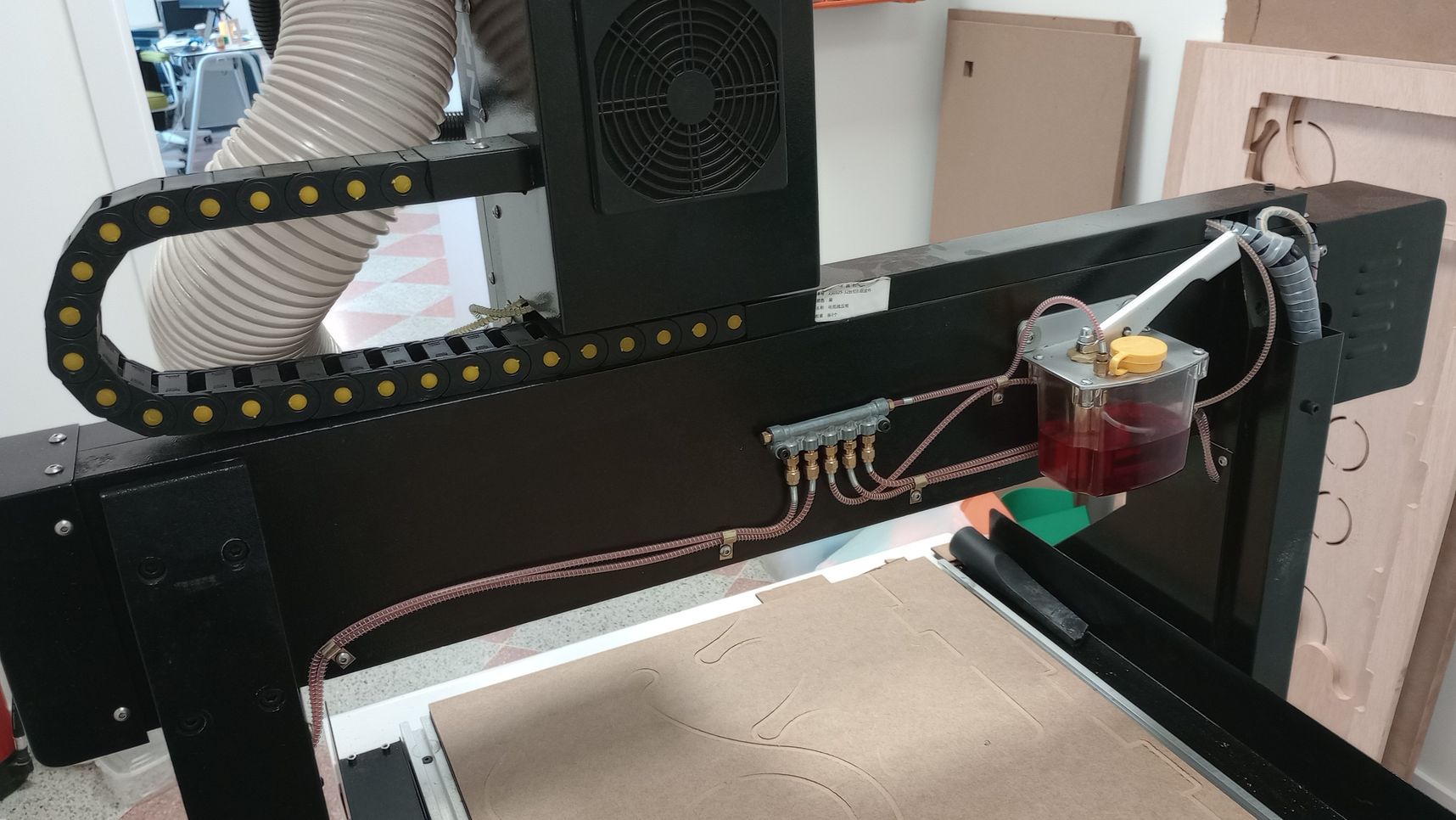
The machine is a small size CNC which is located inside a cabin with local extraction. The CNC has a vacuum table and a dust collection system.
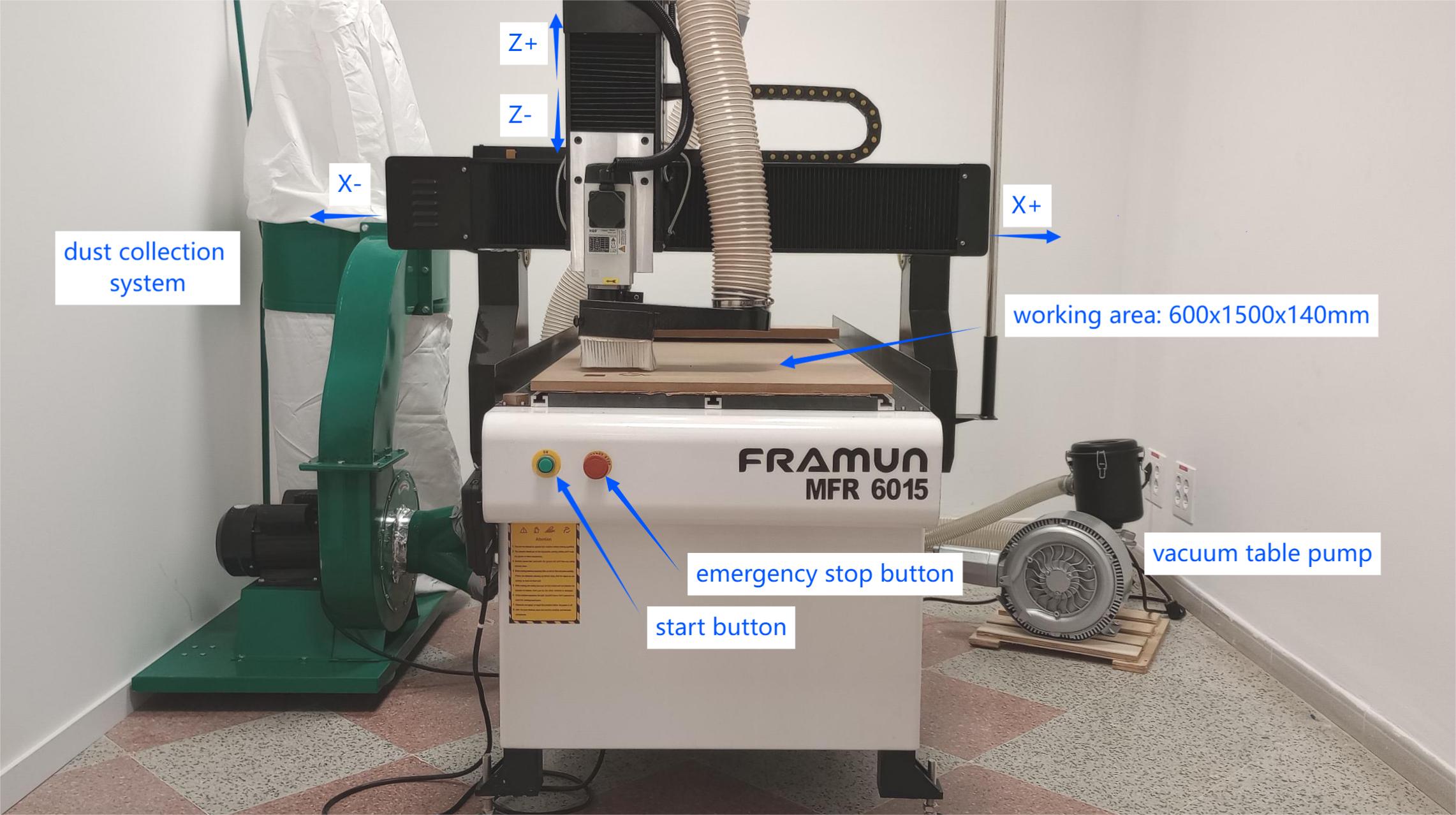
Technical specifications:
| Model | Framun MFR 6015 - (Rebranded Blue Elephant ELECNC6090) |
| X,Y axis travel | 600x1500mm |
| Z axis travel | 140mm |
| Spindle | HQD 2.2Kw, 18000 rpm |
| Inverter type | 2.2kw |
| Control system | DSP A11 |
| Driving system | Stepper motor 450A with driver Leadshine M542 |
| Transmission | X, Y, Z axis: ball screw |
| Traveling speed | 25m/min |
| Working speed | 20m/min |
| Re-positioning accuracy | ±0.03mm |
| System resolution | ±0.003mm |
| Working accuracy | ±0.07mm |
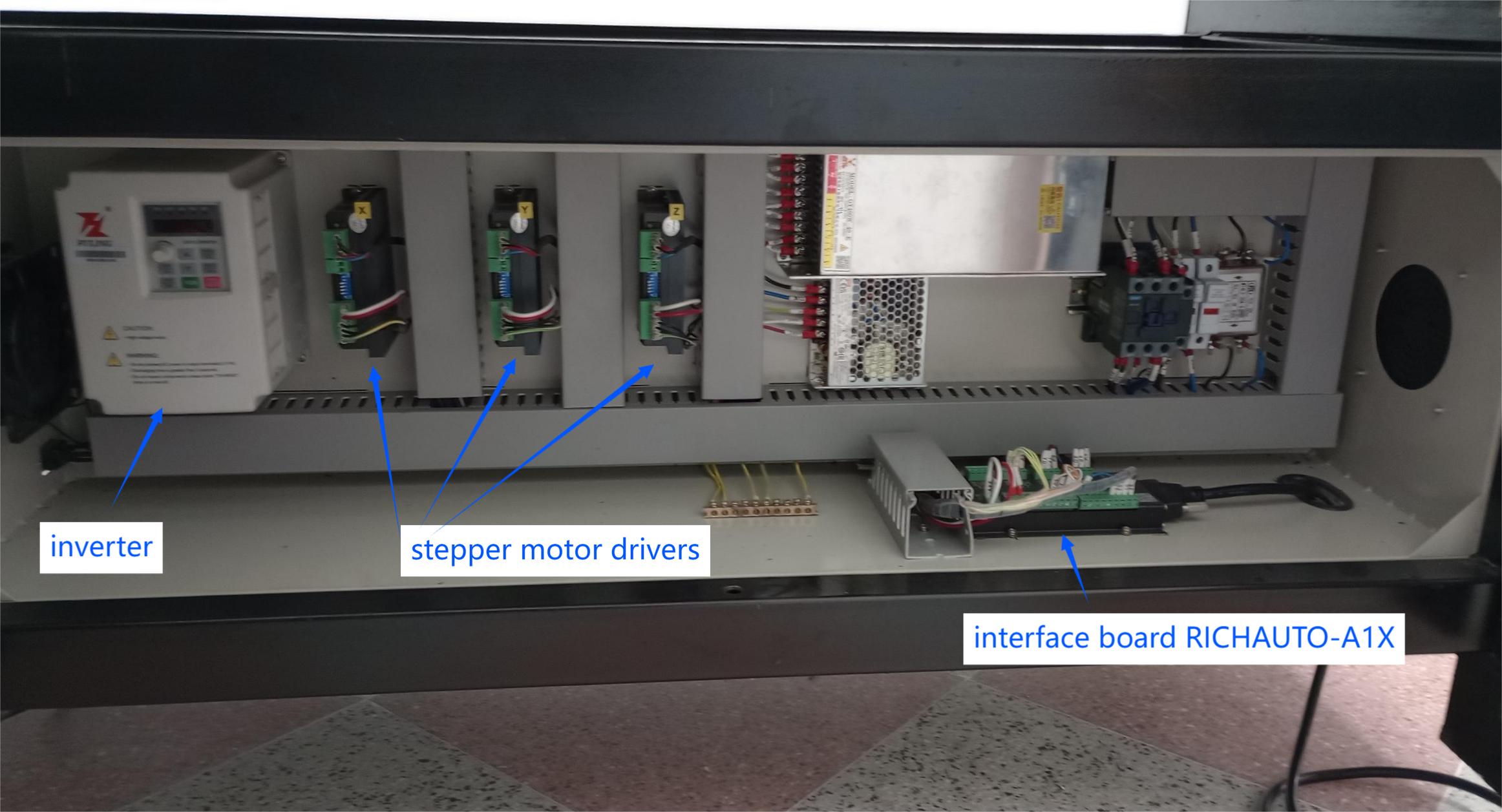
The motion control system of the CNC is a RichAuto A11 which controls the 3 axis. At the back of the gantry of the CNC we find the lubrication system.
HEALTH AND SEAFETY USING THE CNC
HAZARDS
- Trapping: Fingers can become trapped between moving and fixed parts of machines that are not fully enclosed.
- Entanglement: Long hair, dangling jewellery or loose clothing can become entangled with moving parts that are not fully enclosed.
- Dust: Dust can be emitted when cutting materials if the machine is not fully enclosed.
RISK ASSESSMENT
- Trapping: Machines that are not fully enclosed, and cutters used for thin sheet materials which do not normally have guards fitted, present a risk from trapping.
- Entanglement: Entanglement could occur if the user is too close to a machine which is not fully enclosed or which starts unexpectedly when being set up.
- Dust: Dust will be produced when machining MDF and high-density modelling foam.
CONTROL MEASURES
- To reduce the risk of the machine starting to cut unexpectedly, the person loading the machine should also operate the control that starts the cutter.
- Where machines are not fully enclosed, long hair should be tied back, jewellery should be removed or covered and loose clothing should be secured.
- Some materials are abrasive and can cause rapid tool wear. Care should be taken to ensure that the correct type of cutting tool is used and that the tool is sharp. The use of incorrect or blunt tools may produce excessive amounts of dust and/or heat and therefore increase the level of risk.
- At least two persons must be present when setting up and operating the machine. One person will be designated the operator, which will be in charge of setting up and controlling the machine.
Setting up for operation
- Two persons should handle large boards and heavy items to reduce the risk of back injury.
- Ensure the workpiece material and thickness are correct for the job.
- Ensure the vacuum pump, dust extraction and emergency stop buttonare in good working order.
- Always ensure that you wear proper ear protection and a pair of safety glasses when operating a CNC machine.
- Whenever you are handling or passing tools, avoid touching the cutting edges.
- Ensure the work piece is properly clamped or held to the bed.
- A qualified person should check the setting of the work before cutting is started.
- Before starting ensure the dust extraction, the vacuum table pump and the local extraction are switched on.
During operation
- Keep your hands away from any moving parts during machining processes.
- Stand clear of the machine whenever it is operational. You should also warn any other people near the risk of being too close to it.
- Do not leave the machine unattended during operation.
After operation
- Ensure that you turn the machine off completely and clean it whenever you have finished using it.
- Check the the cut for burntor charred edges. If the cutting operation generated excessive heat, hot wood dust and chips may have entered the dust collocation system and may cause a fire.
MAINTENANCE
To keep the CNC machine running smoothly and safe, it’s important to follow a regular maintenance schedule. Here's a maintenance schedule devised for the CNC machine available in our fablab, which includes weekly and monthly tasks.
Weekly Maintenance
General inspection:
- Perform an emergency stop to check the system works properly.
- Check sacrificial board is not damaged or broken.
Clean the machine:
- Hoover and wipe down the machine with a clean cloth to remove dust and chips.
- Clean the work area around the CNC.
Lubrication:
- Ensure all moving parts (rails, lead screws, etc.) are well-lubricated.
- Check that the lubrication system is functioning properly and the lubrication tank has enough oil.
Inspect the spindle:
- Run a short cycle or idle time and check for unusual sounds or vibrations.
- Ensure the spindle is running smoothly and without overheating.
Check tool integrity:
- Inspect the tools for wear and tear or damage.
- Replace any damaged or worn tools.
Dust collection system
- Always wear safety gear such as a dust mask when emptying or cleaning the dust collection  bag to avoid inhaling fine dust particles.
- Empty the bag regularly to ensure the system continues to work efficiently. The frequency of  emptying depends on your level of usage
Monthly Maintenance
Inspect all wiring and cables:
- Look for any wear, fraying, or loose connections.
- Ensure that all connectors are tight and in good condition
Examine the dust collection system:
- Deep clean and empty the dust collection bin.
- Check the level of suction of the system
- Inspect the dust collection system's ductwork and connections for leaks
- Check the dust collection bag for any signs of damage, tears, or loose connections.
Deep clean the machine:
- Perform a more thorough cleaning of the machine’s interior, including removing  accumulated chips in tight areas and checking for corrosion.
Check the ball screws and guide rails:
- Inspect ball screws and guide rails for wear or damage.
- Ensure they are clean and lubricated.
CUTTING TOOLS
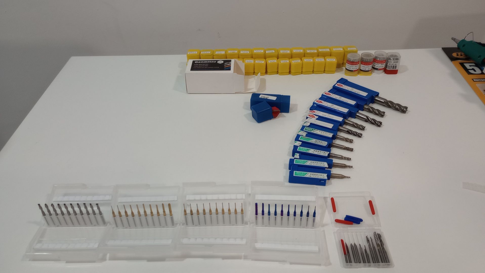
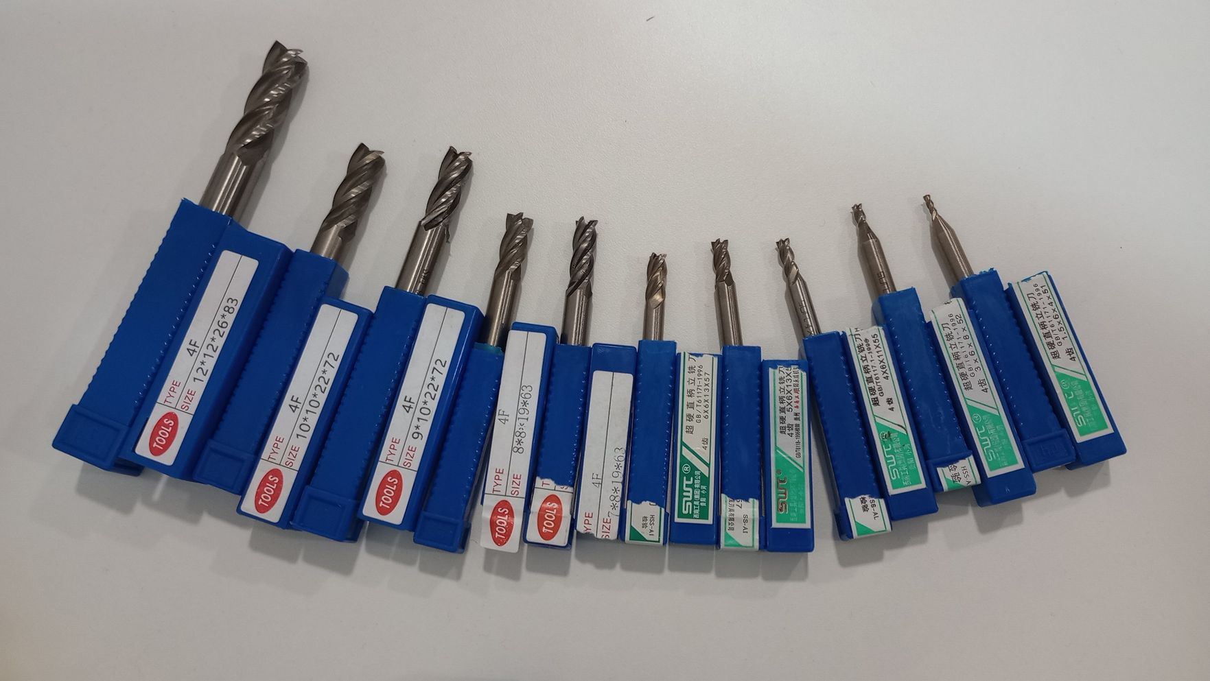
- HSS end mills 4 flutes from 2 to 12 mm diameter
- 2 Flute Flat Nose Spiral Bits
- 2 Flute Ball Nose Spiral Bits
- Titanium Coat End Mills
- Nano Blue Coat End Mill
- Triangular engraving bits
TEST RUNOUT, SPEEDS AND FEEDS.
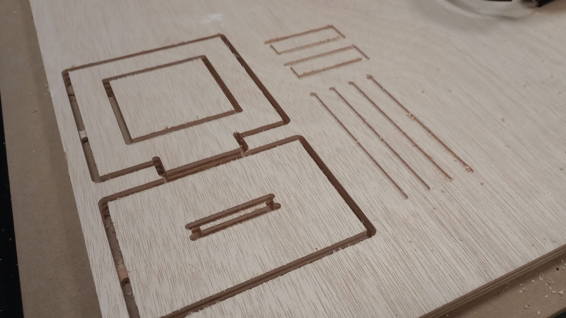
In Fusion I designed a parametric piece to test a T-bone joint and check the dimensional accuracy of the cut. Apart from cutting the testing piece I am also testing the difference between the climbing and conventional toolpaths.
Material: 15.60 mm thick plywood board.
Cutting tool: 4-flute 6mm diameter end mill.
In order to calculate the feed rate I look for Chip Load values.
Chip load is the thickness of material that is fed into each cutting edge as it moves through the material.
Feed Rate = RPM x number of flutes x chip load
RPM=18000
Number of flutes = 4
Chip load for plywood and 6mm tool = 0.06 (between 0.046 and 0.1)
Feed rate = 18000x4x0.06= 4320mm/min
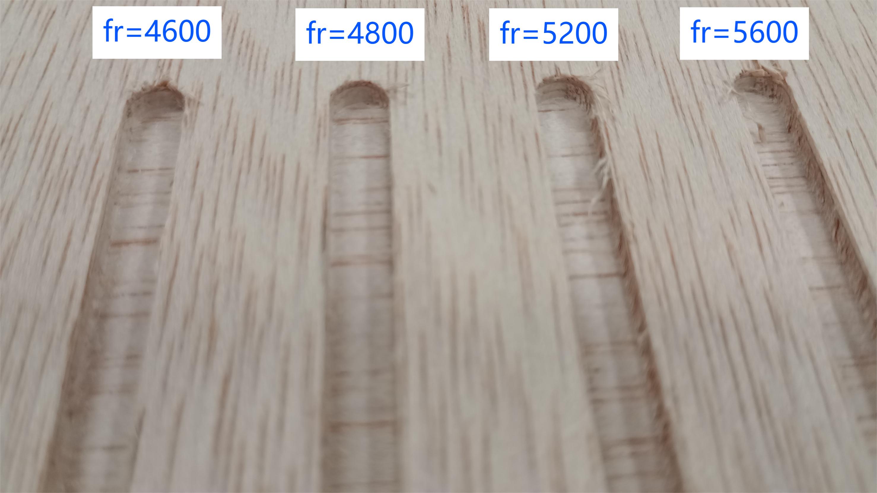
As I am not familiar with the CNC I am starting with a conservative feed rate of 4000mm/min. I am also testing cutting at different feed rates: 4600, 4800, 5200 and 5600 mm/min.
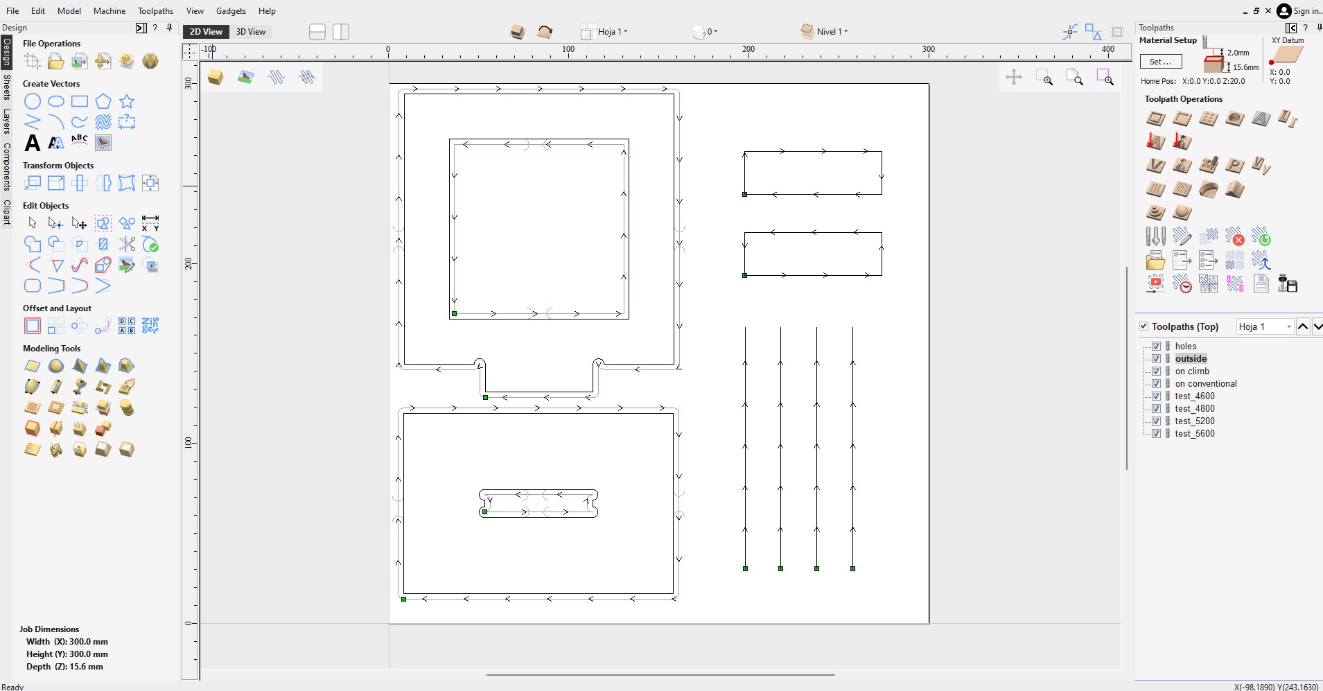
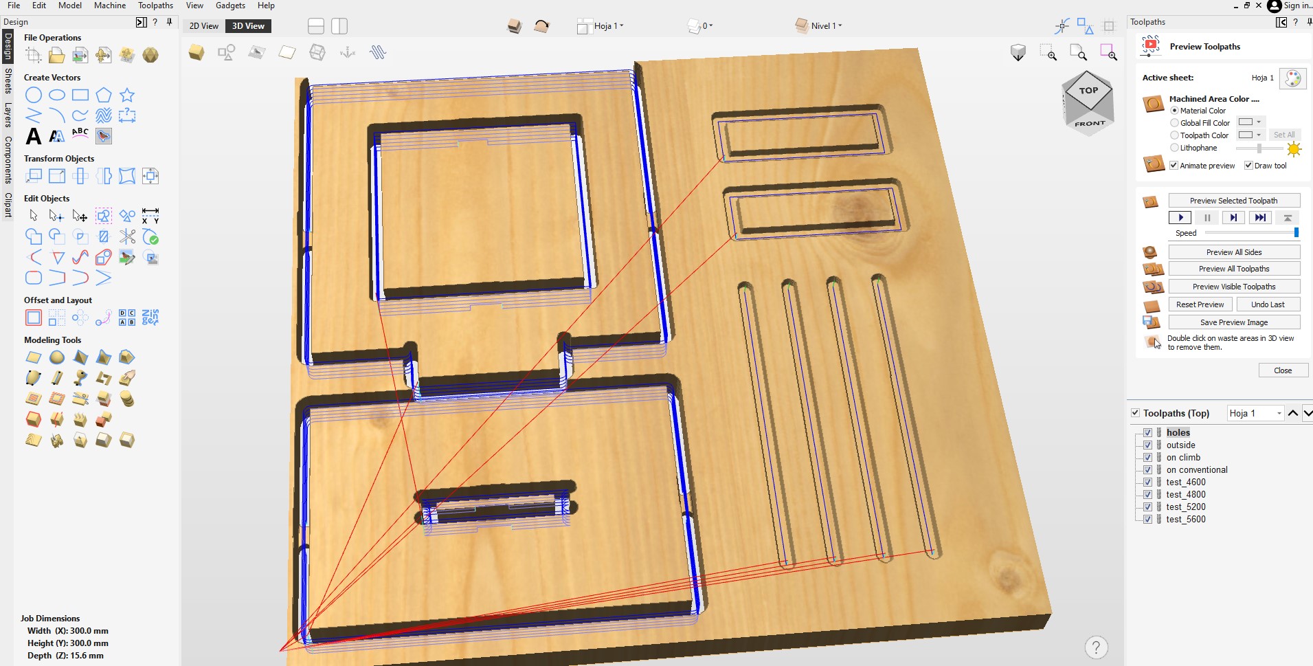
In the software Aspire I define the stock piece, the cutting tool, the toolpaths and add tabs to stop parts from moving during operation. As the material is 15.6mm thick I add a cut depth of 15.8 mm to ensure the material is cut all the way through.
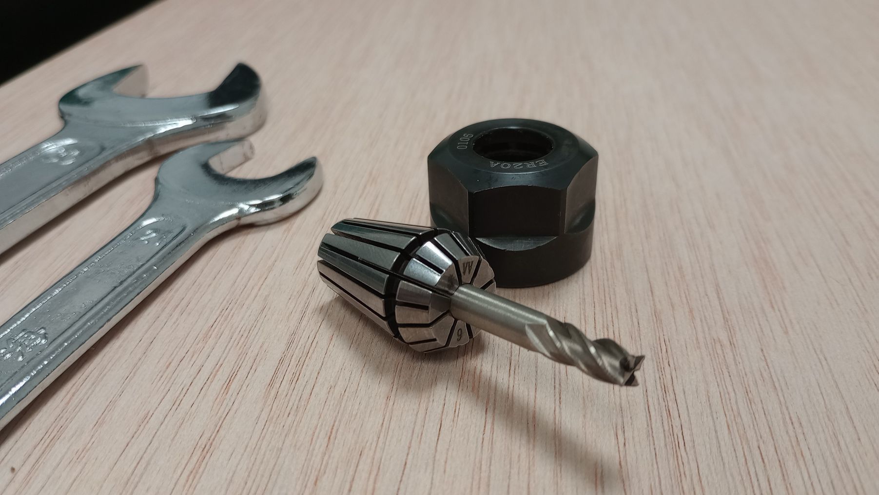
In the CNC I fit the collet with the 6mm cutting tool in the spindle.
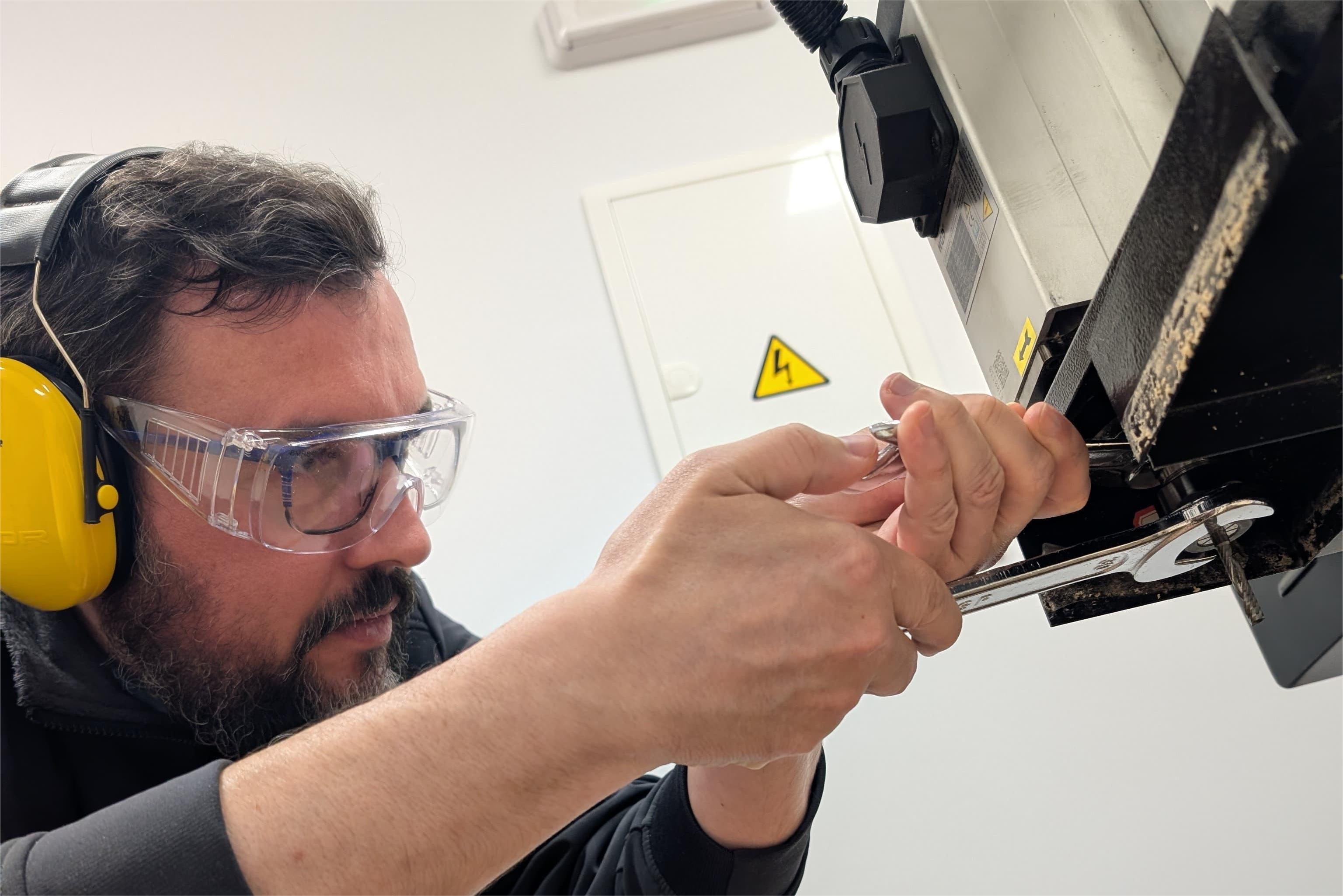
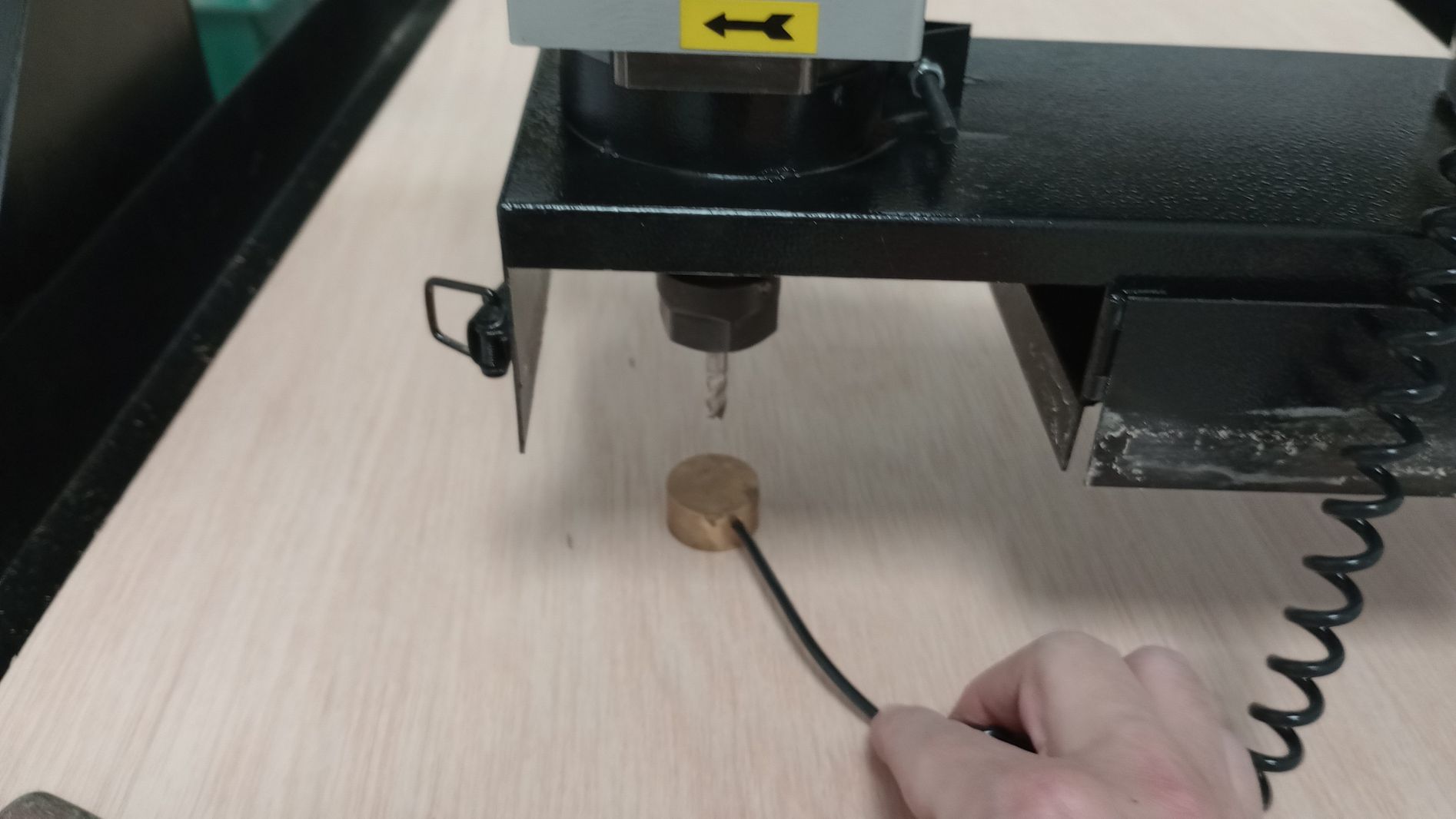
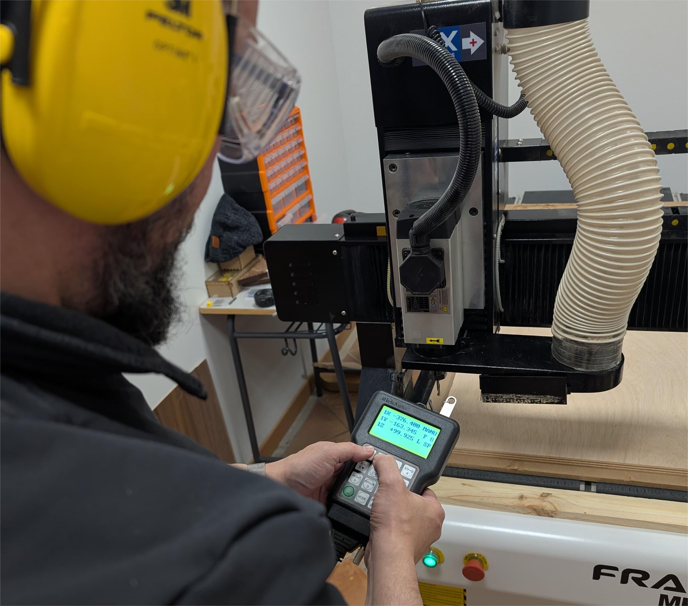
I fix the board to the bed using clamps and before setting-up the origin I start the vacuum table, as this affects the Z readings. I set up the Z origin with the touch probe on top of the material. Next, I position the spindle in the bottom left corner, making sure I am clear of the clamps and set up the XY origin.
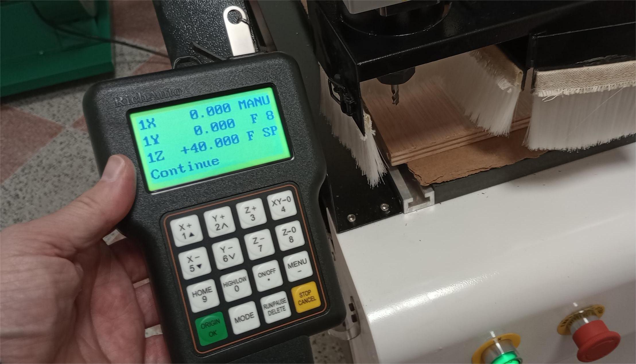
The RichAuto hand-held controller uses one-touch buttons and combination buttons to achieve different operations.
- To start the automatic Z-axis originset up with probe: press MENU + ON/OFF
- Set X axis and Y axis work origin: press XY->0
- Go back to origin: ORIGIN OK
- Run or pause processing: press RUN/PAUSE button
- Change spindle speed during processing: Z+ to increase and Z- to decrease speed
- Change feed speed during processing: Y+ to increase and Y- to decrease speed
I switch on the dust collector and I run the job.
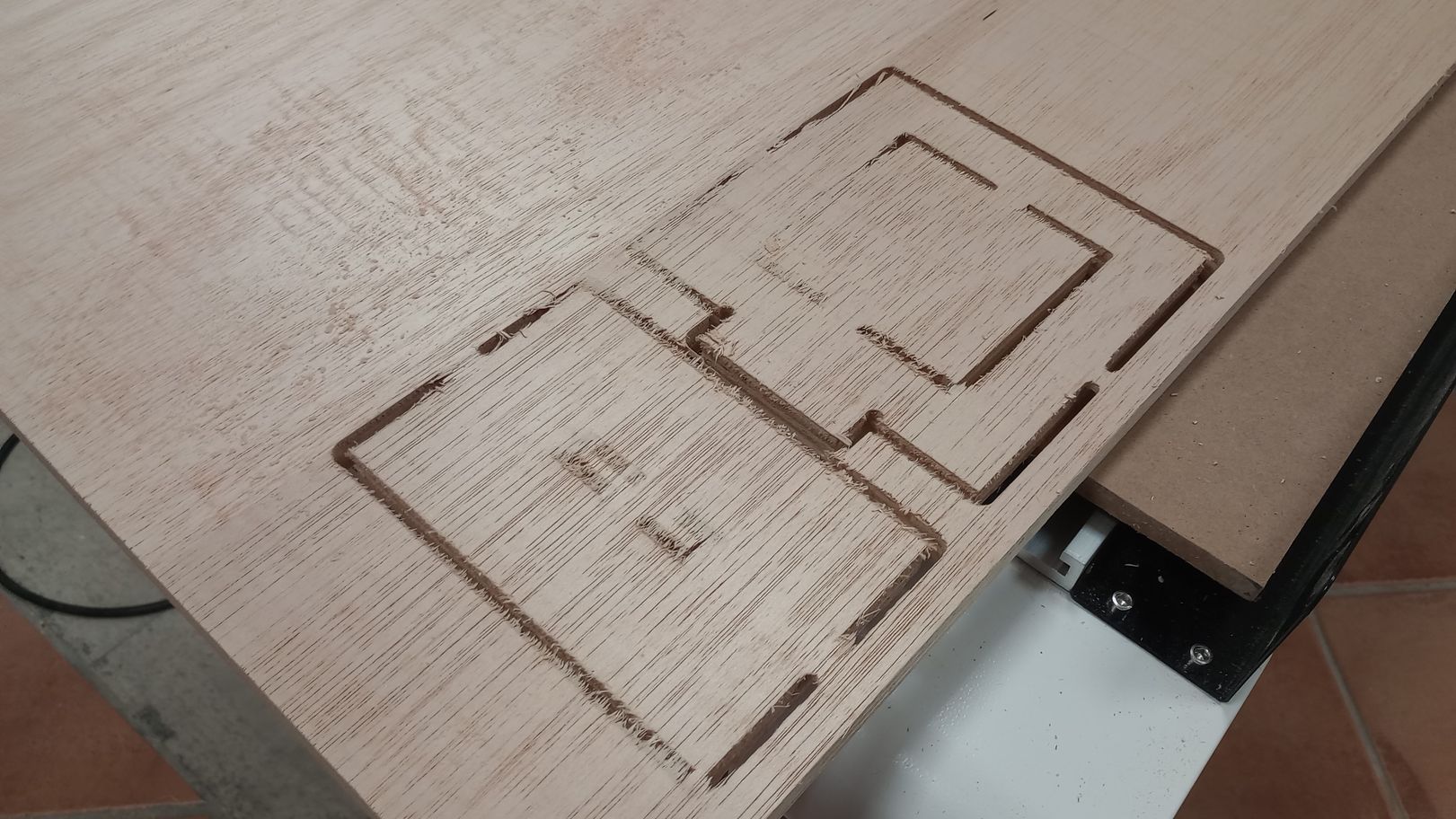
The results are good, although I realise that the cut depth was not enough to provide a clean cut on the back of the plywood board. For the next job I will increase the cut depth to avoid this problem.
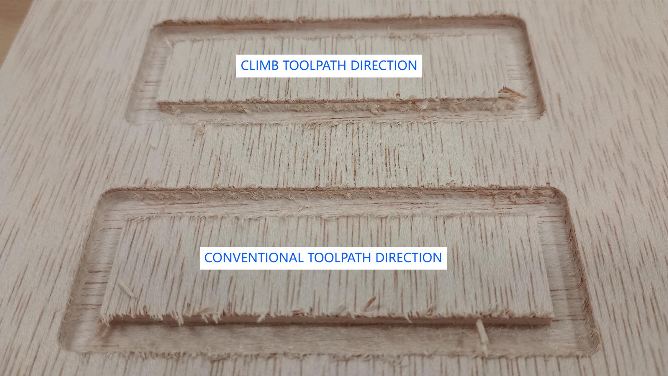
The toolpath direction test results are shown in the photo below. There is not a significant difference between the climb and conventional directions; however, the climb direction produces a slightly cleaner cut when cutting across the grain.
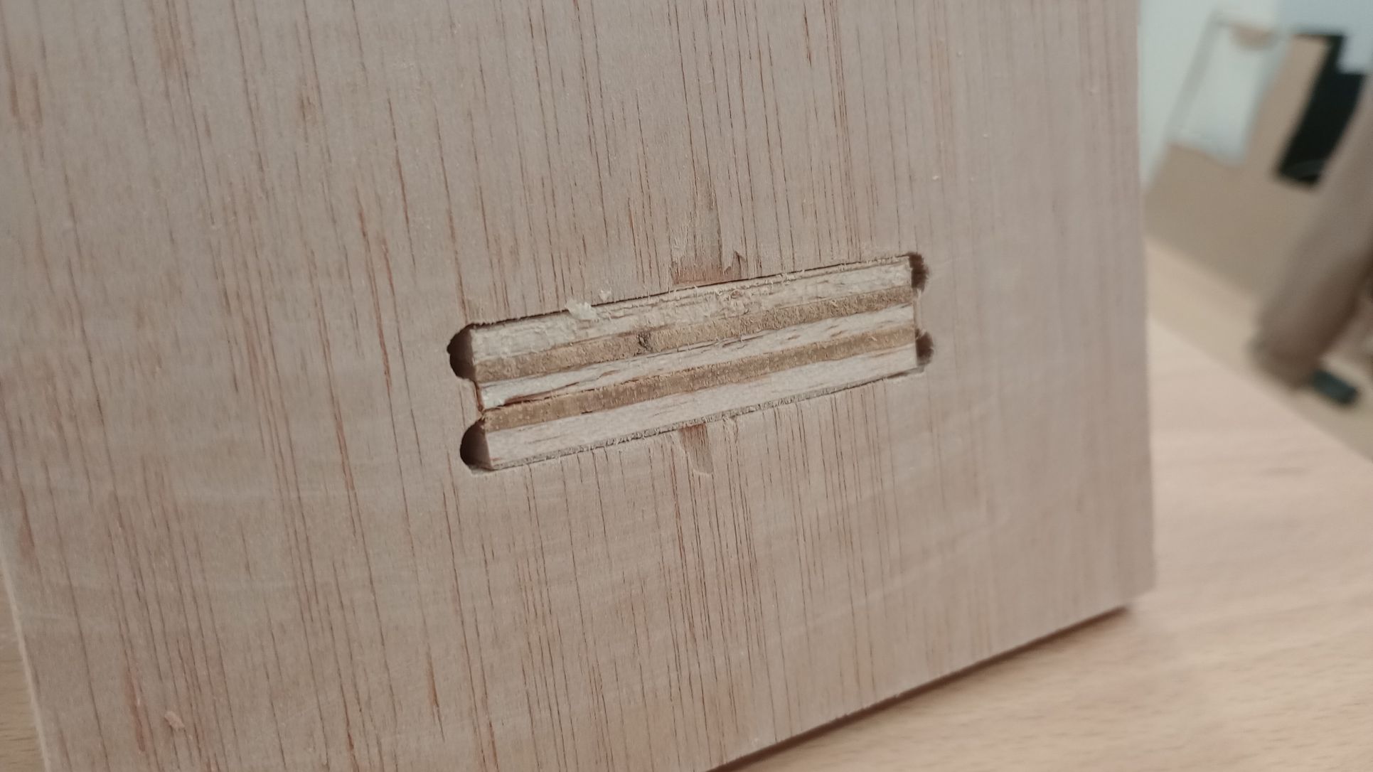
The T-bone joint was a bit too tight and required a bit of filling. I will take this into account for the individual assignment, so I cut the joint with an allowance for a better fit.
The feed rate test at different speeds resulted in similar quality edges, with a bit more fraying on the edges at higher speed rates.
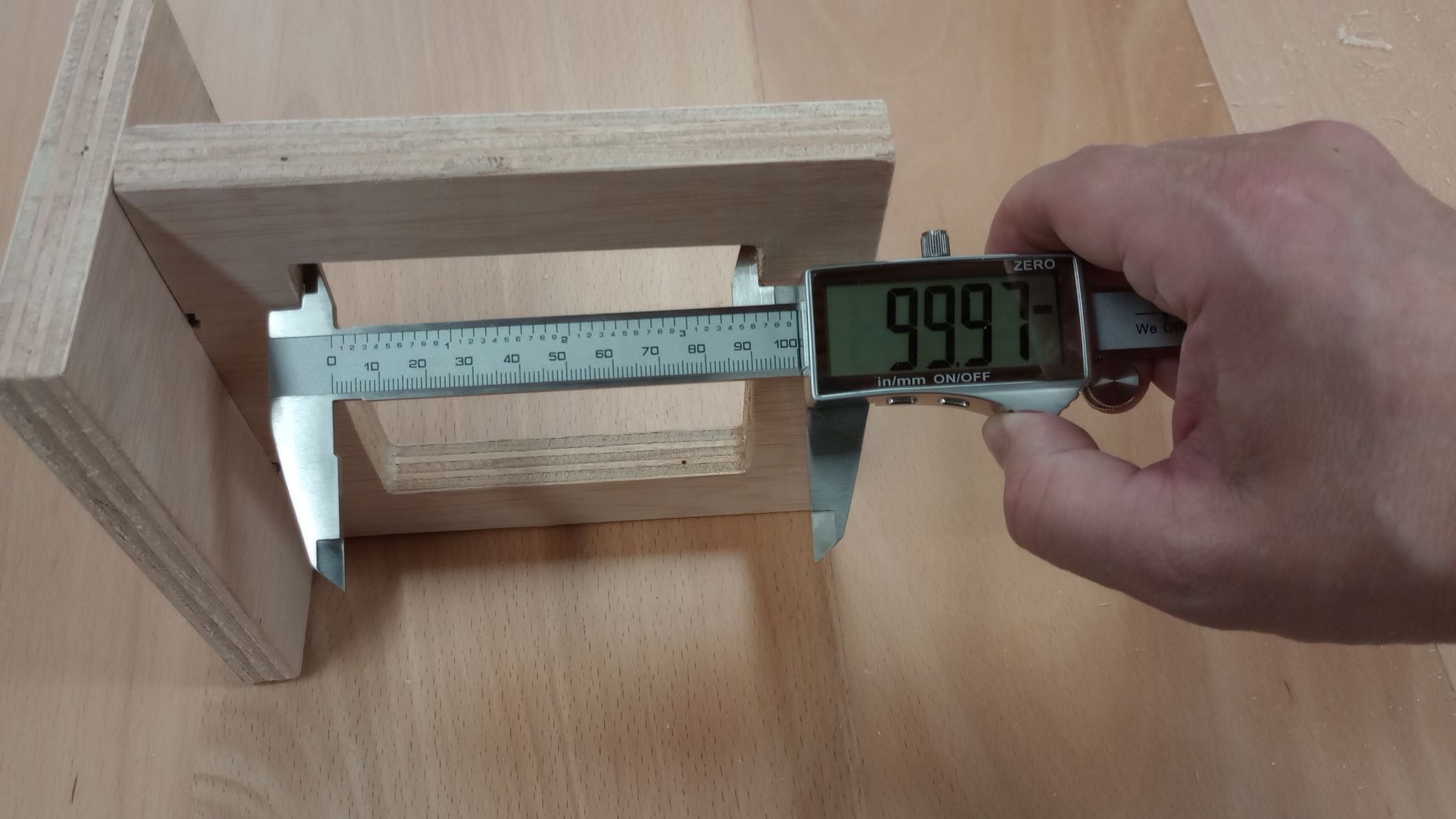
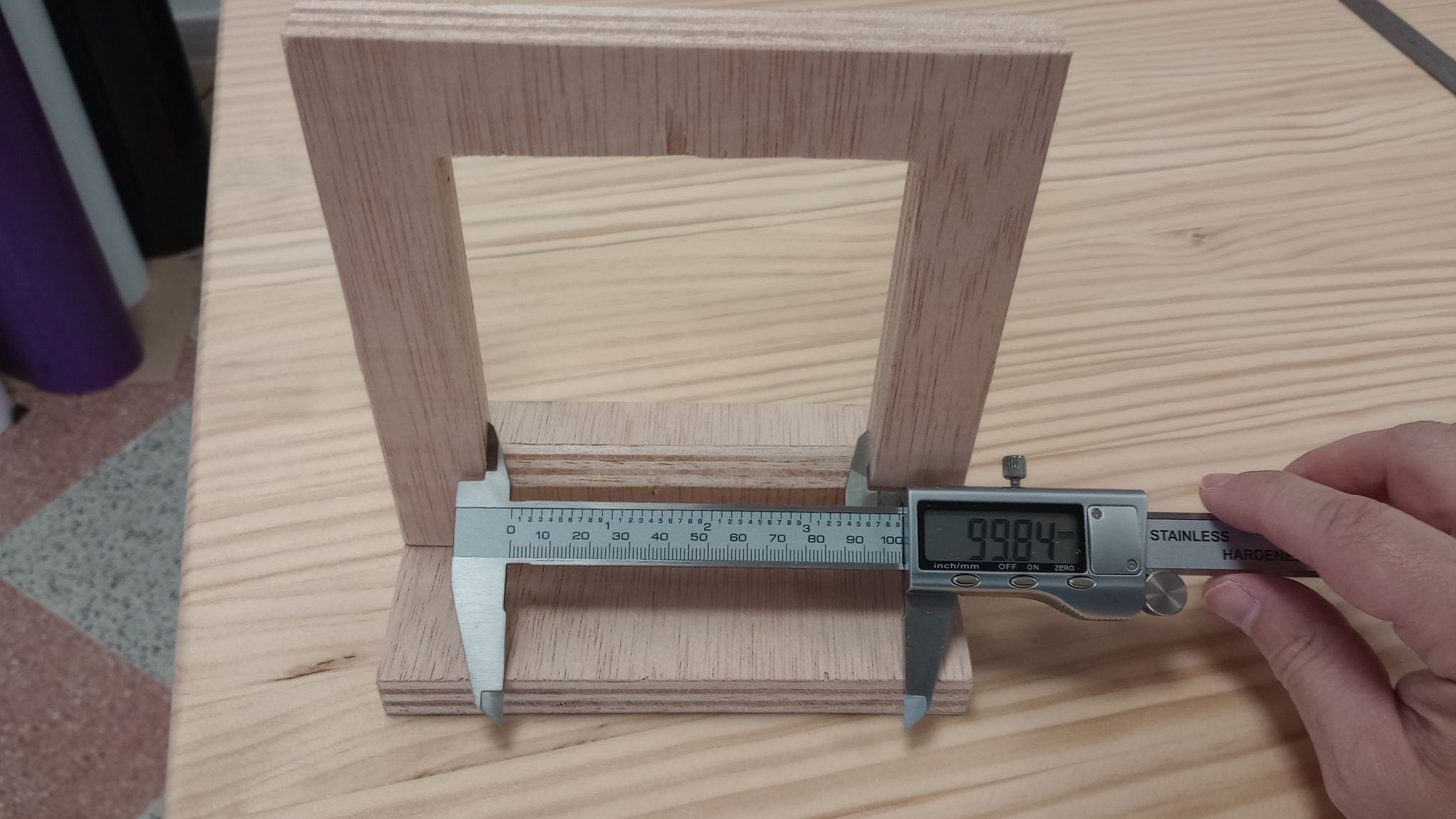
I check the dimensions of the inside square which are a -0.03mm in the Y direction and -0.16mm in the X direction.
Top
INDIVIDUAL ASSIGNMENT: DESIGN FOR CNC
DESIGNING FOR CNC CUTTING
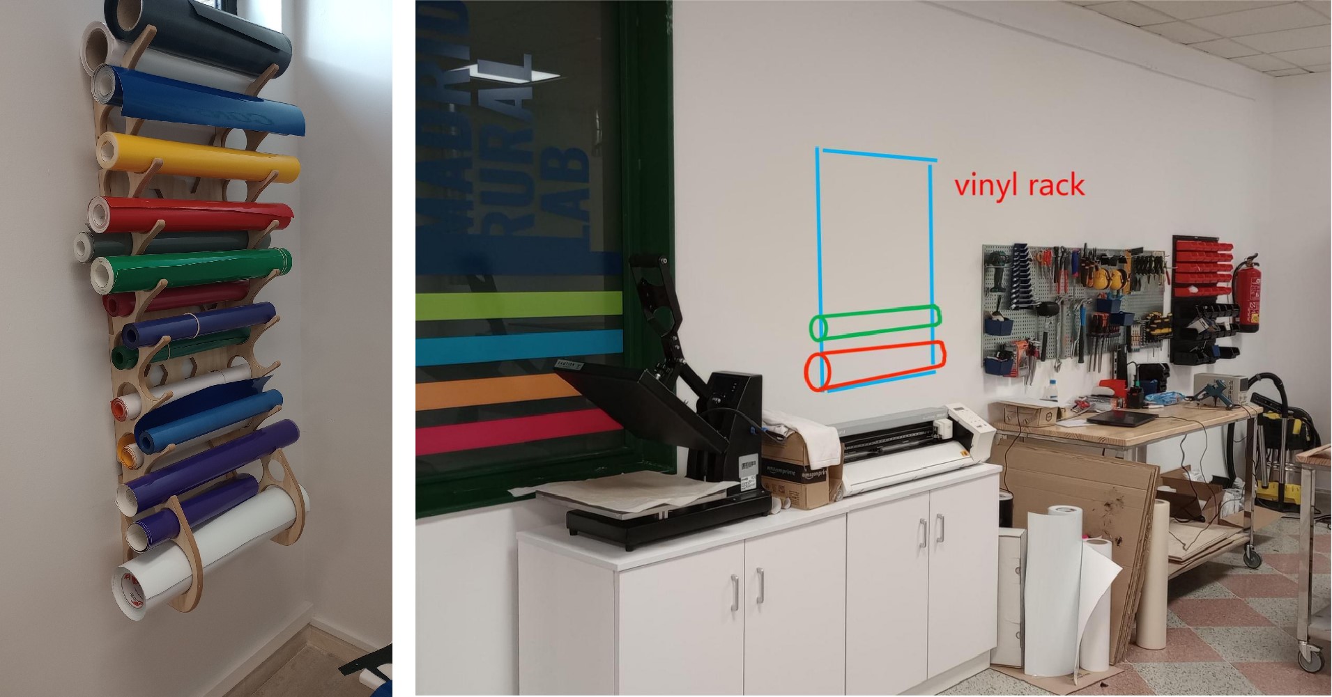
We have a need in our lab for a storage solution to store vinyl rolls so I decided to create a design based on the one made by one of my colleagues. The rack will be fitted on the wall and will be made of a board that I will select form the available stock.
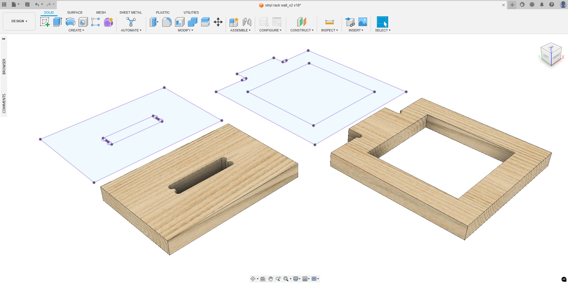
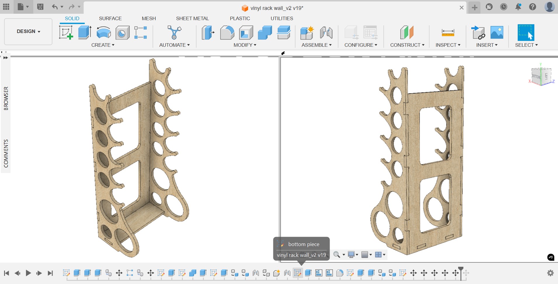
I start by creating a parametric model of the vinyl rack on Fusion. I create a sketch for the lower part, which holds bigger rolls and another sketch with a part that I can copy and stack on top each other to add more storage capability to the rack.
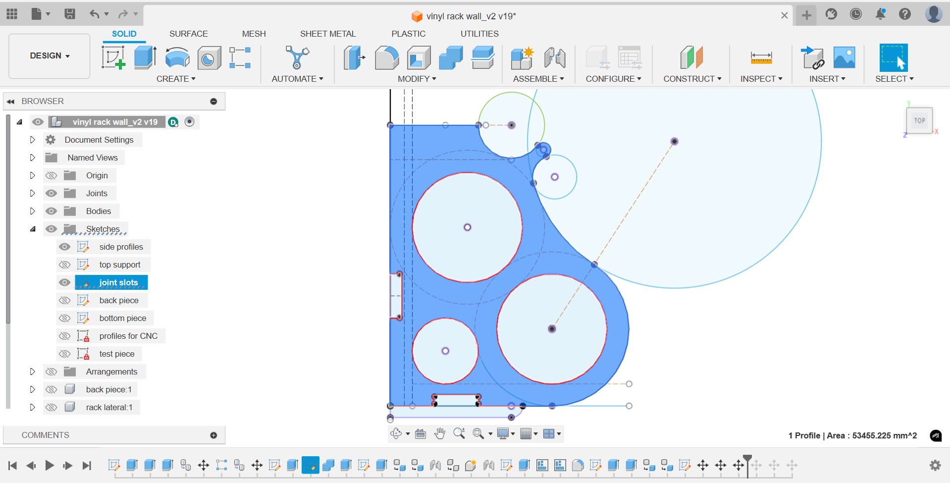
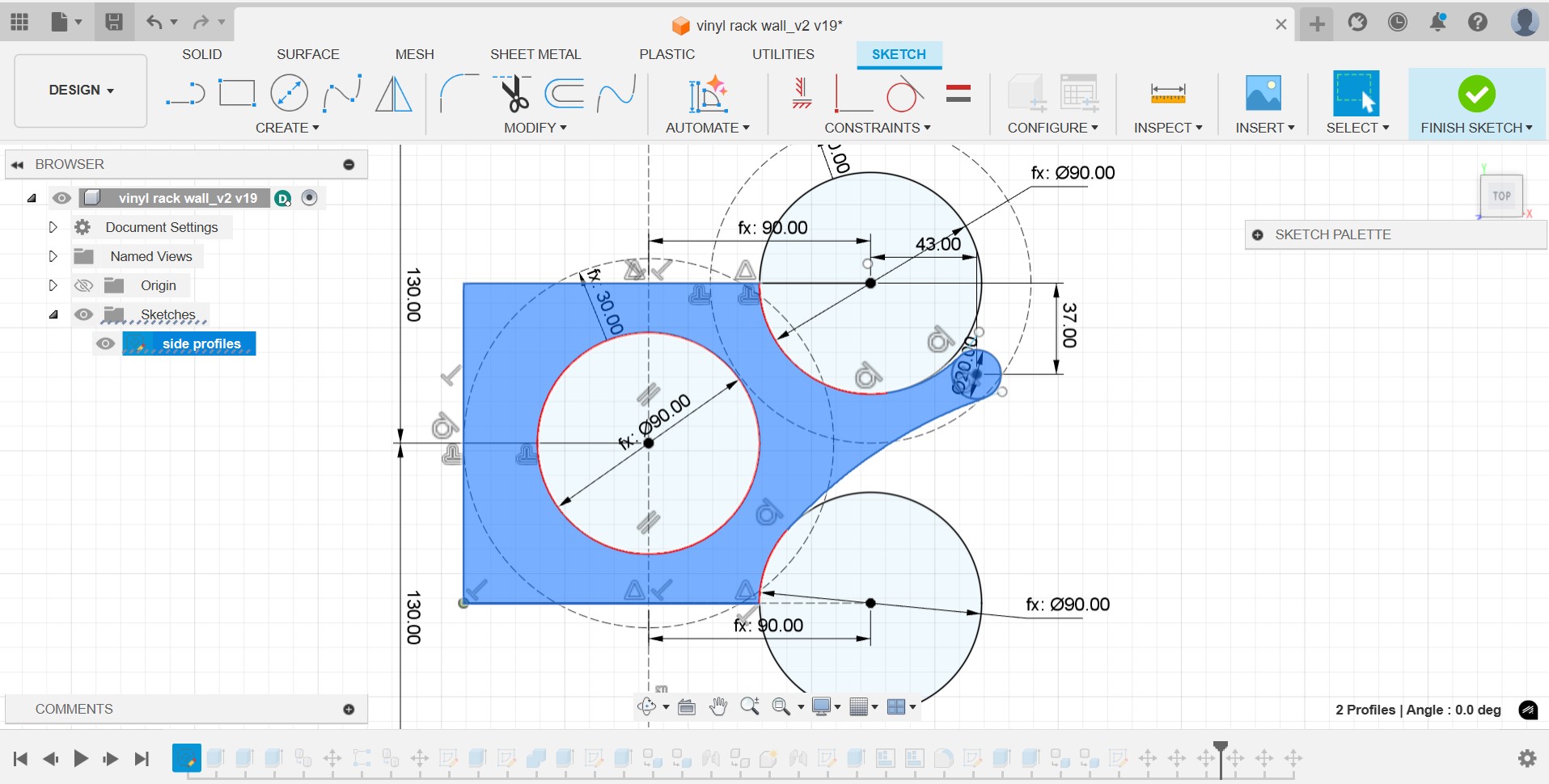
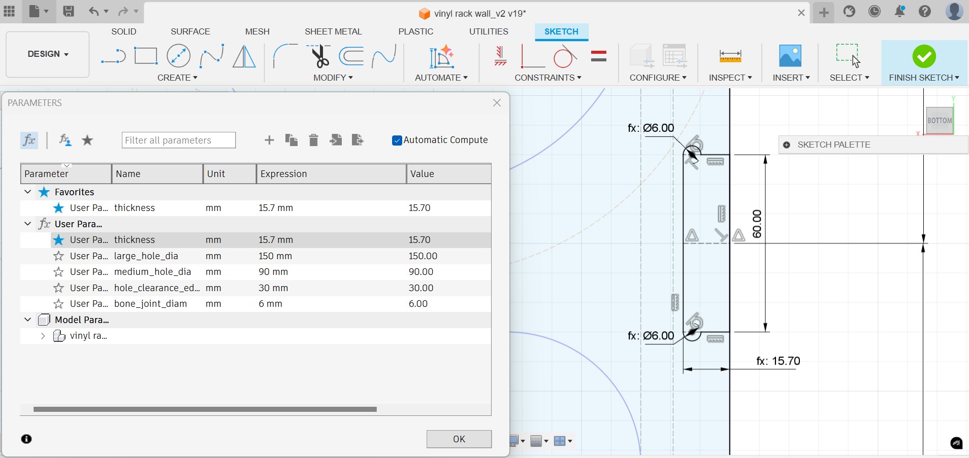
I create several parametric dimensions, such as the thickness, the diameter of the holes and the clearance between holes. The joints between the sides and the back will be T-bone joints but glue will be required as the joints in this case will not keep the pieces secure.
I extrude the profiles and add sections on top of each other until I get the desired height.
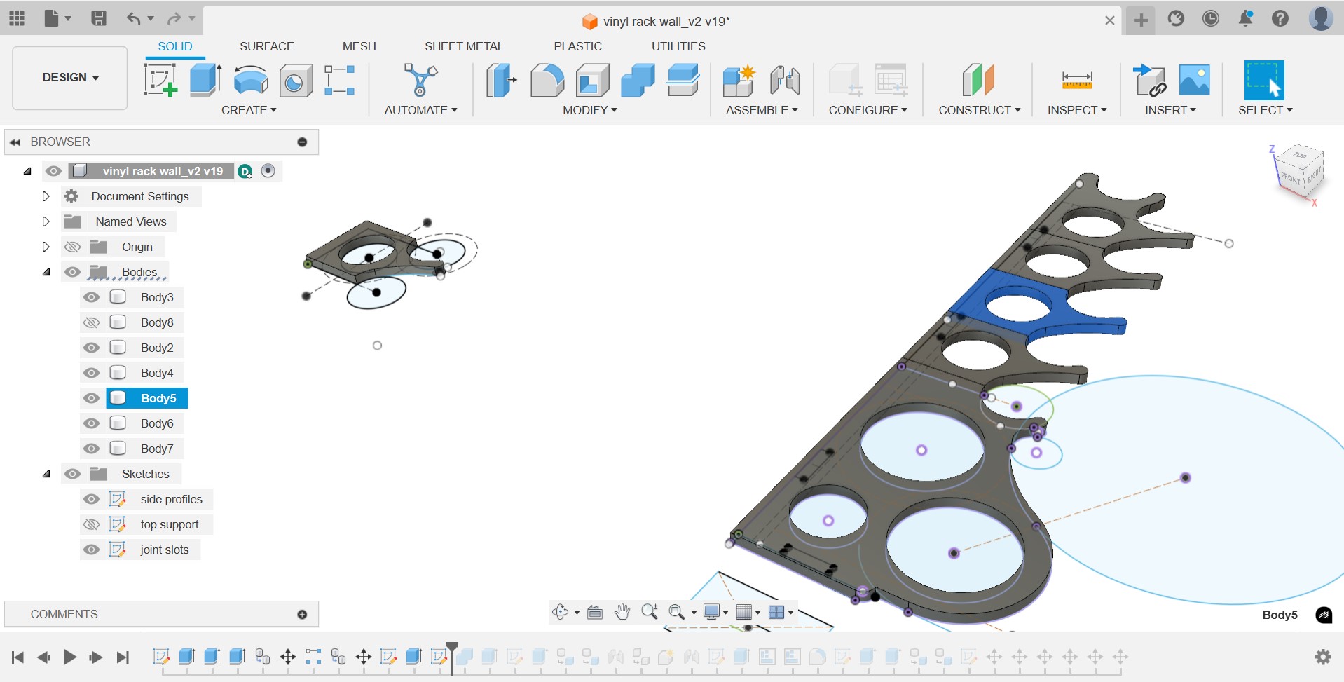
I assemble the design and check the parametric values work well.
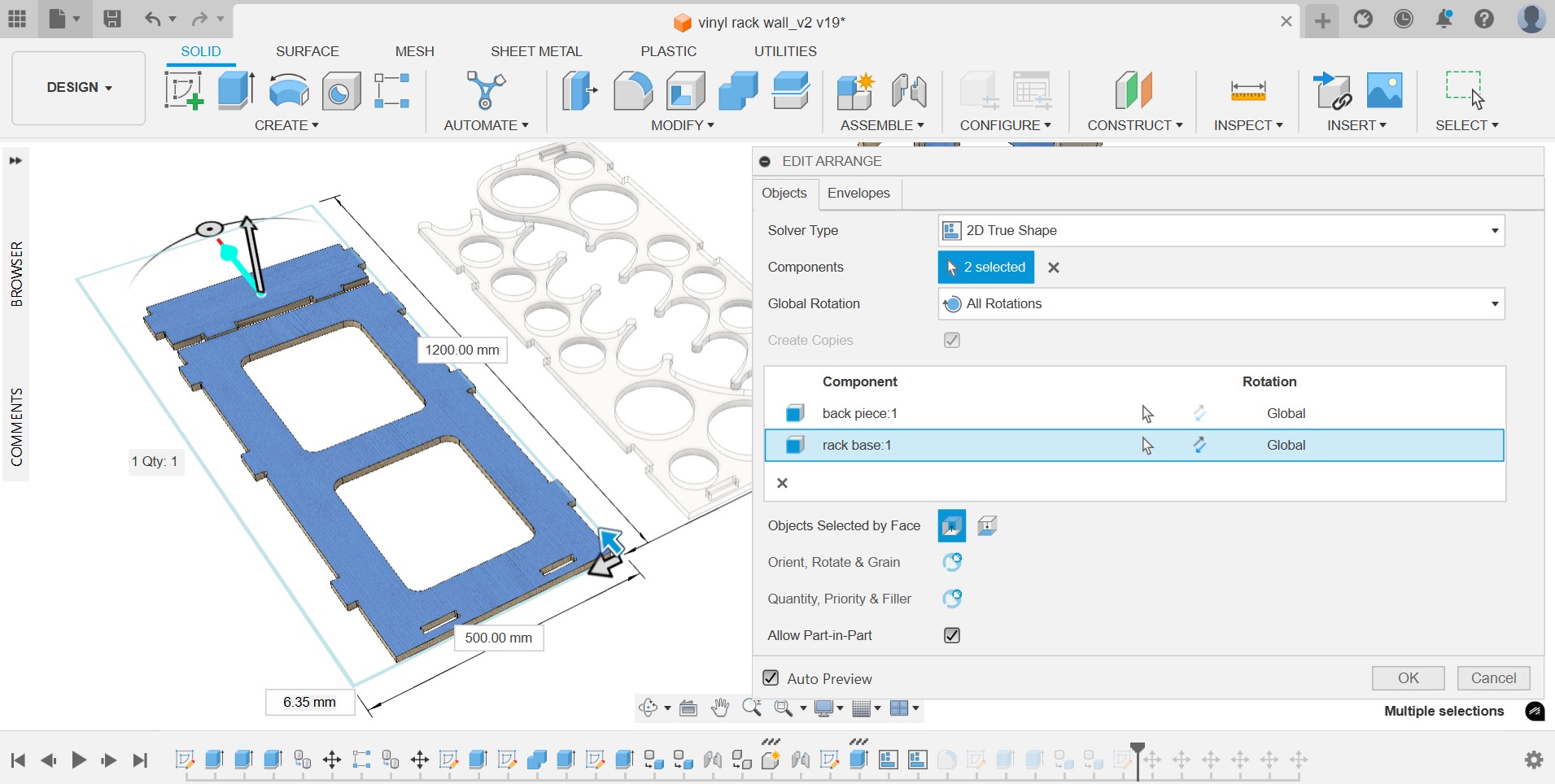
Next, I use the “Arrange” feature in Fusion to define the “envelope” or board dimensions where the pieces are automatically nested.
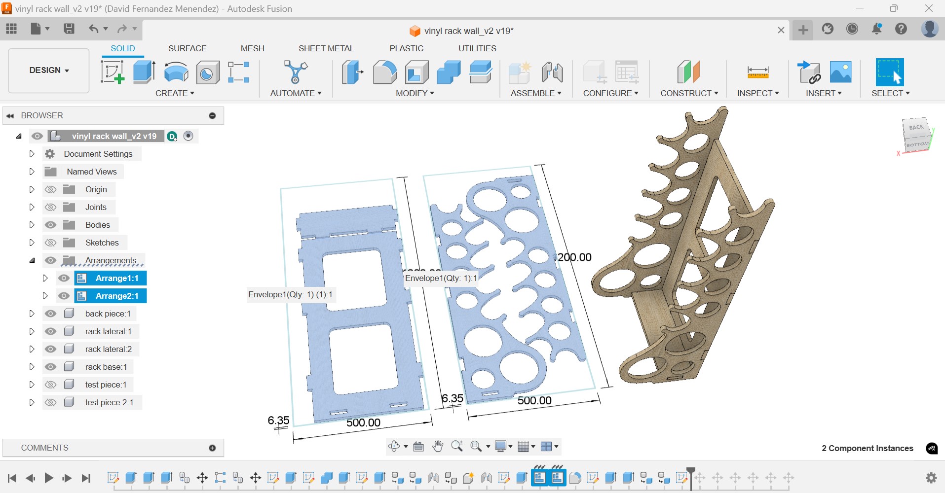
I export the profiles of the pieces as .dxf to import them into Aspire and prepare the deign to be machined.
PREPARING THE DESIGN FOR CNC MACHINE
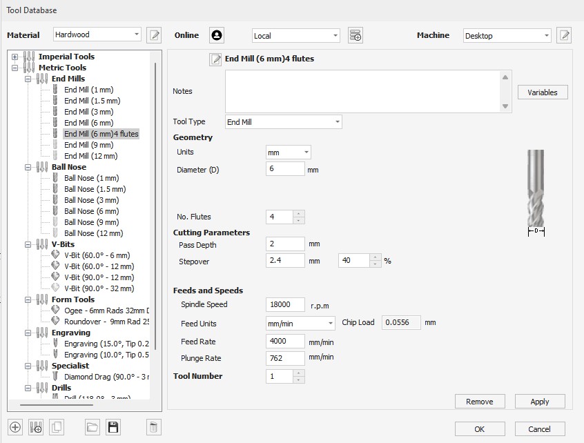
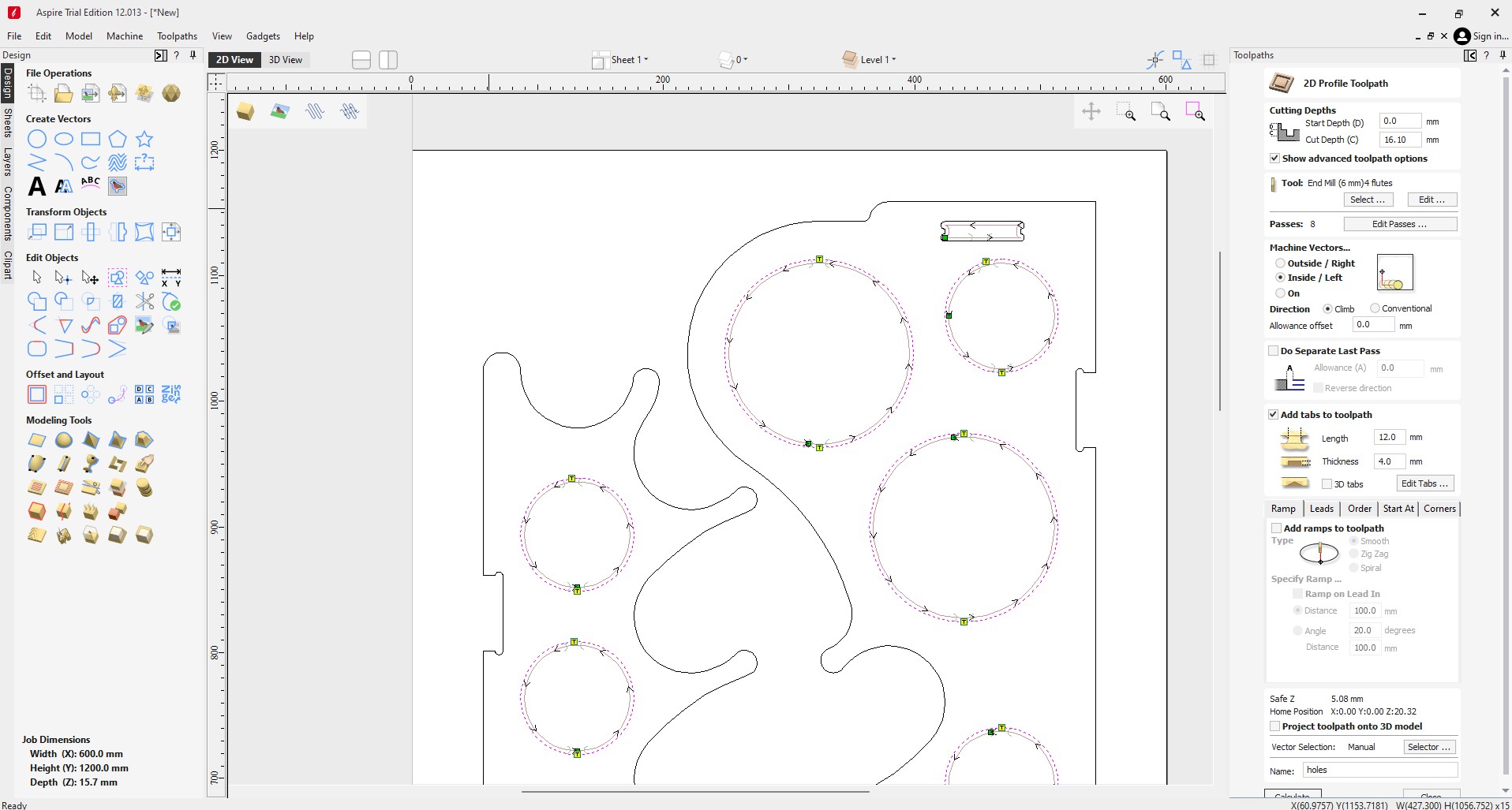
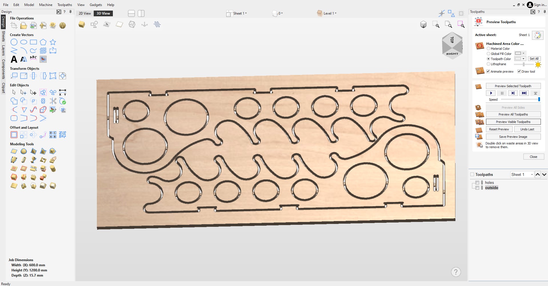
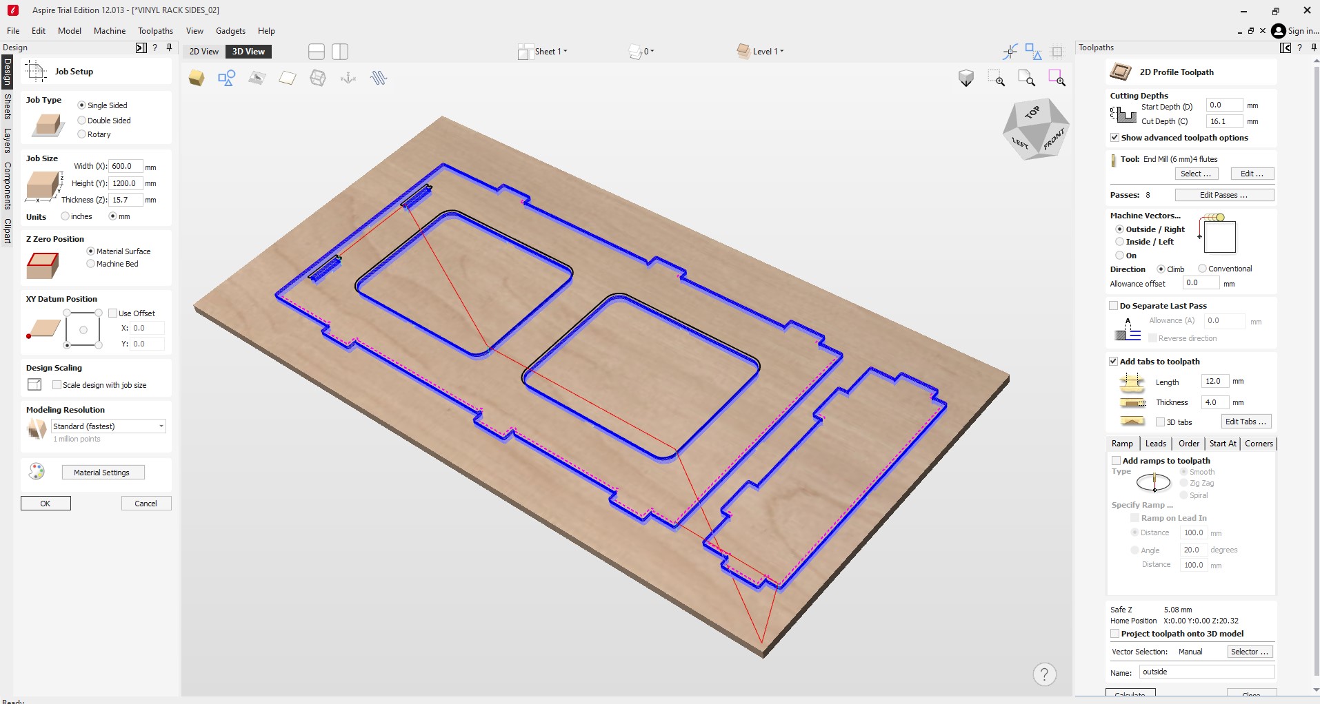
In Aspire I start by defining a stock piece of 1200x600x15.70mm. Then, I import the design and start defining the toolpaths using the “Profile Toolpath”. The toolpath for the holes will be cut on the inside, with the following milling tool:
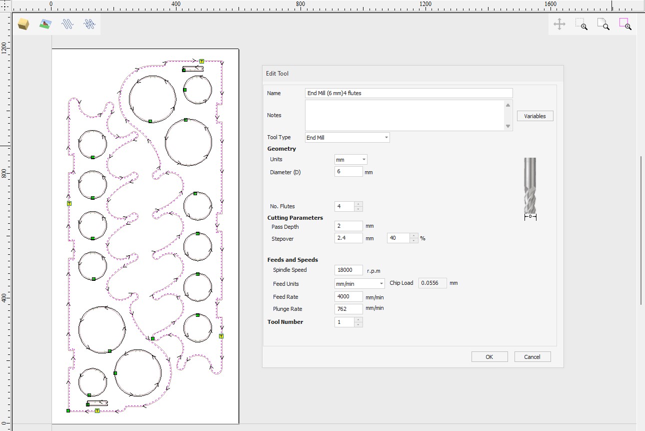
I add small tabs to the circles so the pieces inside are secured during the cutting operation. I create another toolpath for the outside profile, with the same settings but with an outside path. Since I don't have any tool change so I save both tool paths in one file as G-code. (*.tap).
I repeat the same process with the rest of pieces, that will be cut on a separate board.
I save both G-code files on a USB and insert it on the USB port of the CNC controller.
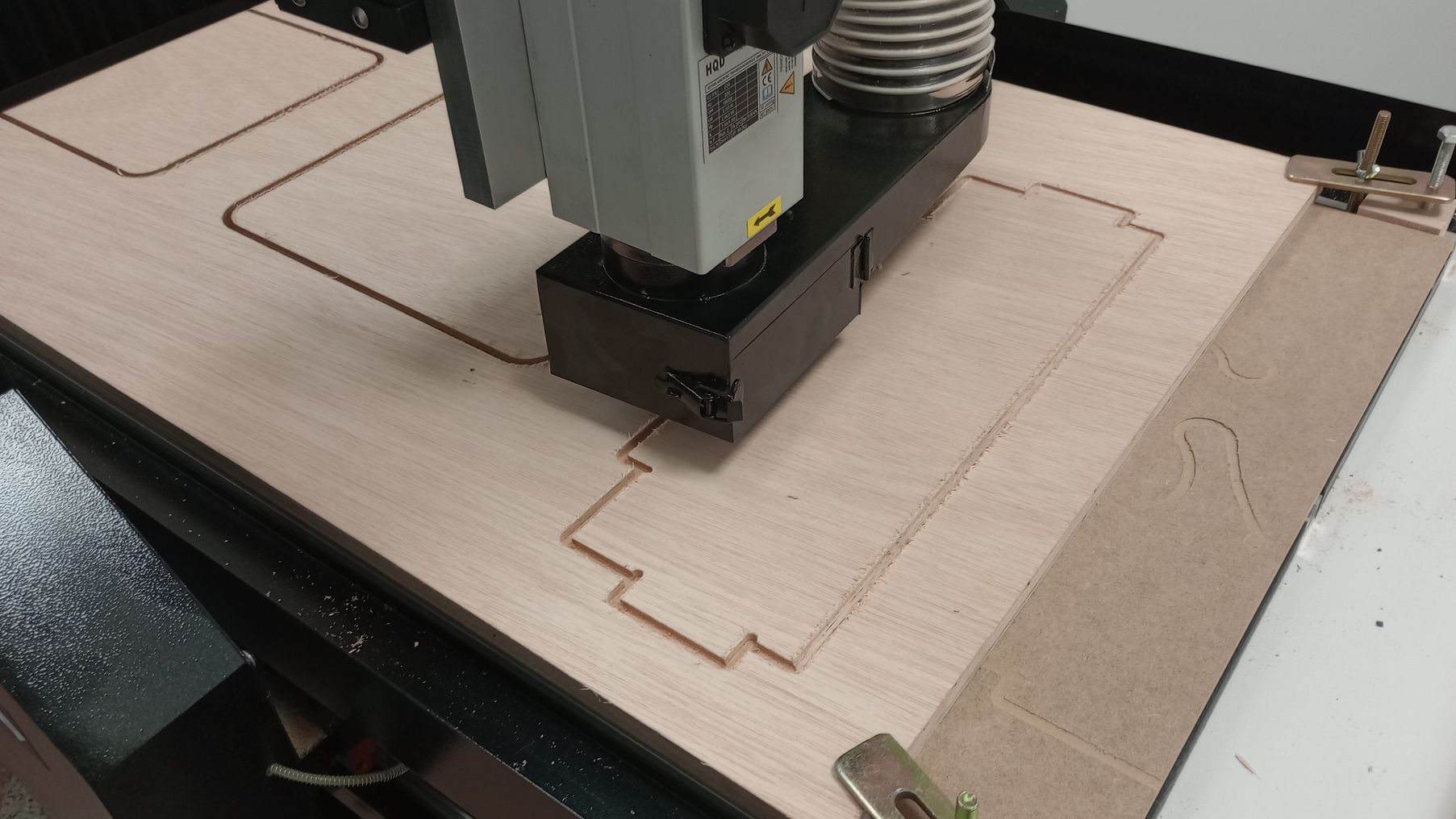
CUTTING ON THE CNC
I started by using a sacrificial piece of 3mm MDF under the plywood board. Because I didn't have enough experience operating this machine, apart from using the vacuum table, I added a clamp on one of the t-slot rails. However this proved to be insufficient as the board moved while the machine was cutting the holes.
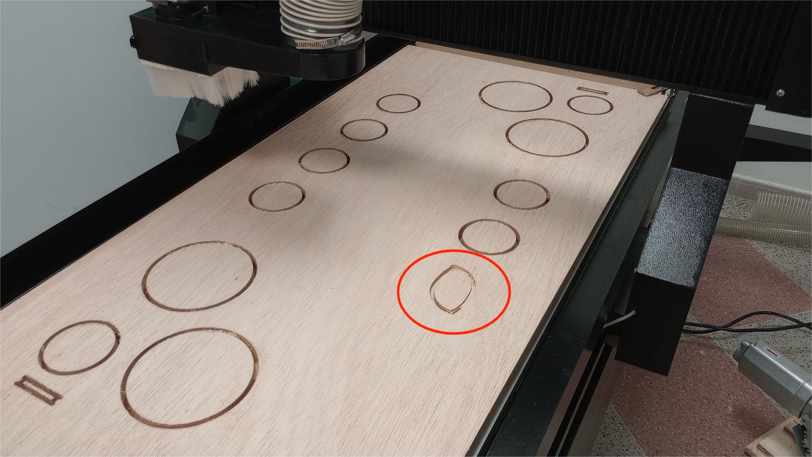
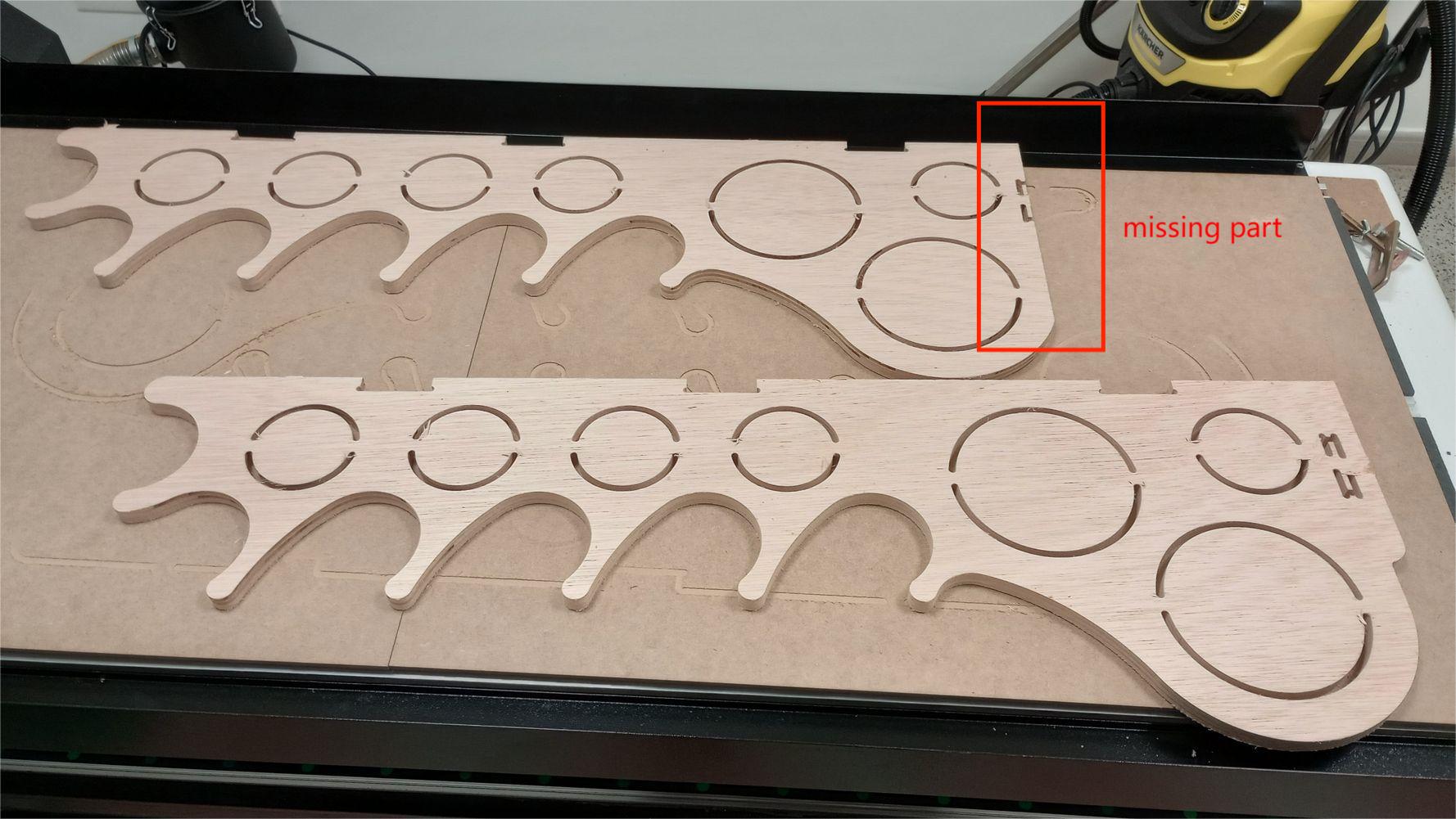
This time, I secured the board with clamps and started the vacuum table again. I set the origin to ensure that the spindle wouldn't hit the clamps. However, this adjustment left insufficient board material, resulting in the lower part of one side having a missing section. Since part of the slot for the joint was still intact, I decided that the part was still useful.
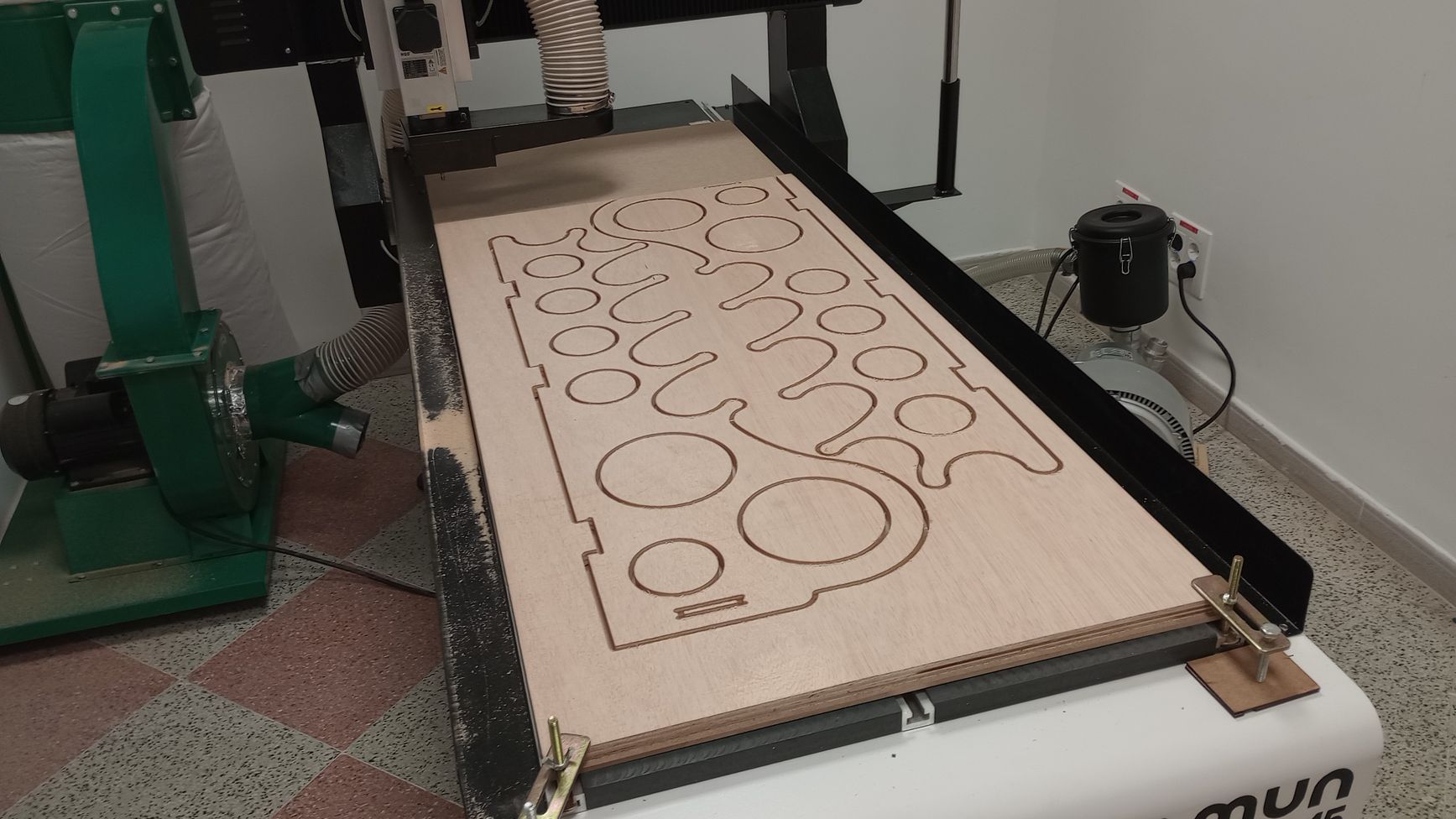
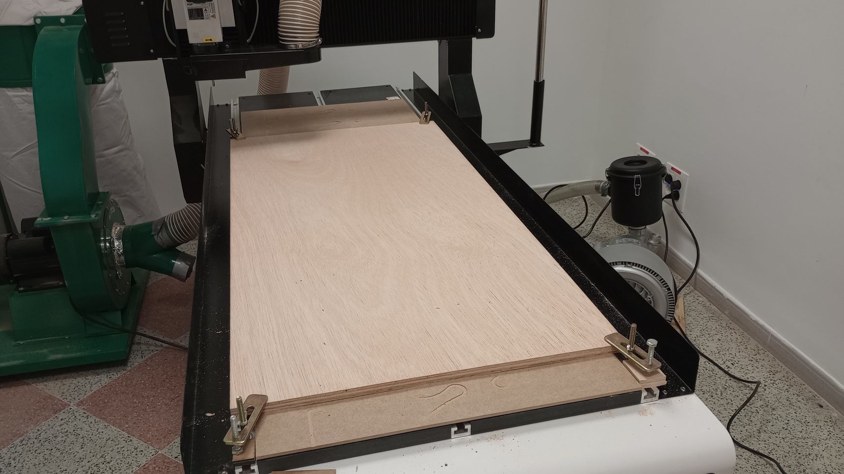
Next, I prepare a new plywood board to cut the back and lower pieces. As before, in addition to the vacuum table, I clamp the board on each corner to ensure it does not move during operation.
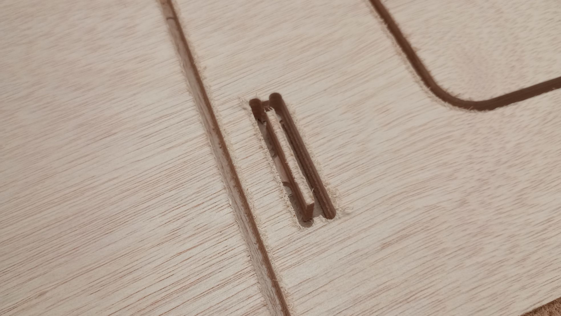
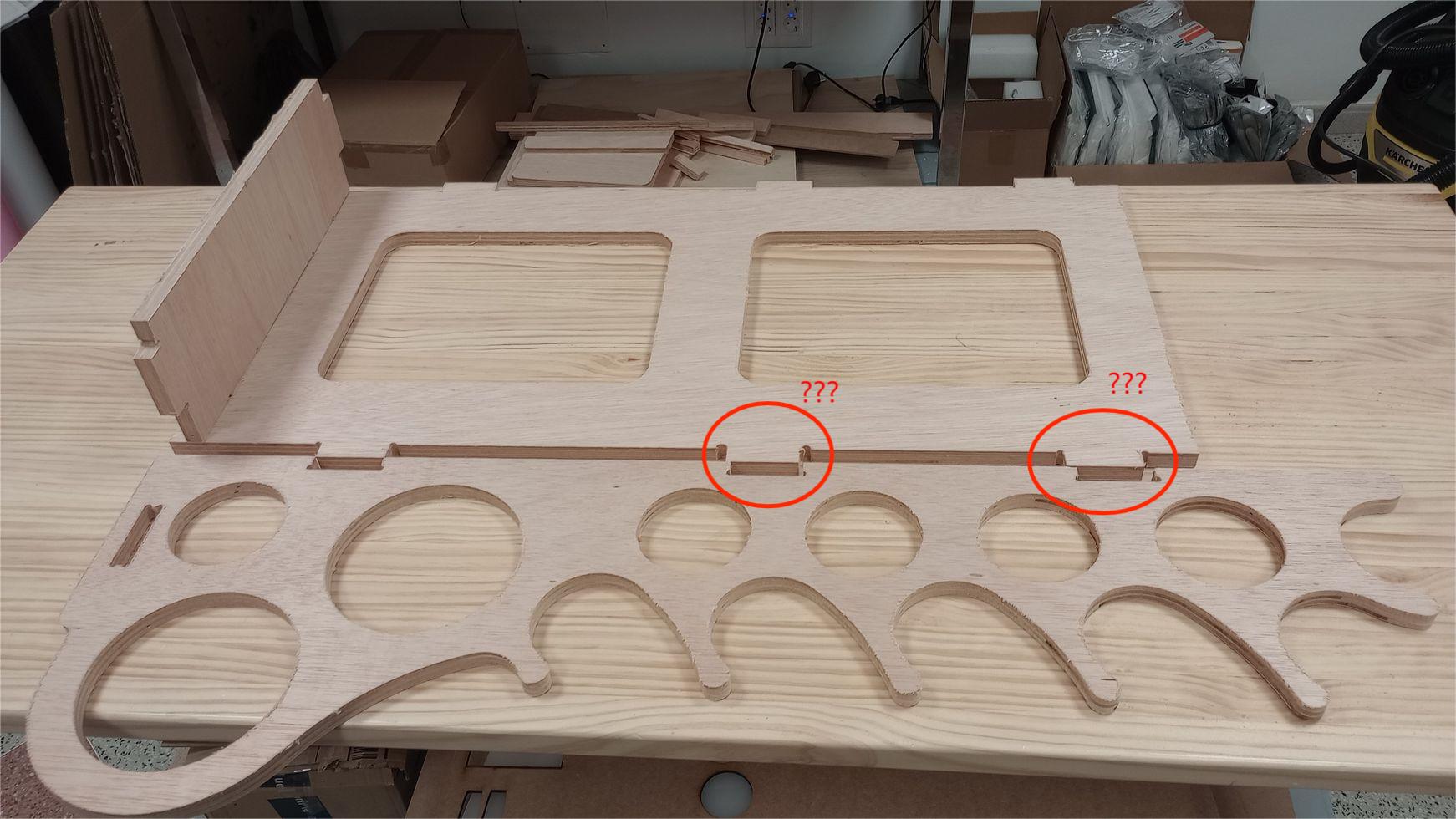
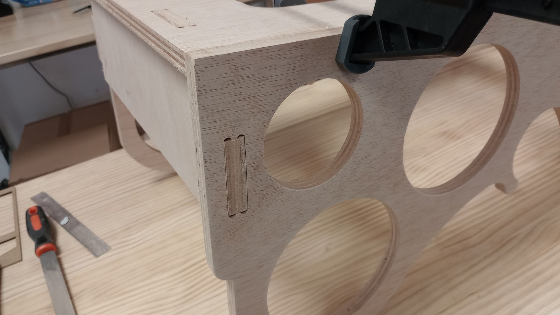
The cutting operation went well, but I bring the side pieces and the back together I realise the T-bone joints do not match. I find this very odd as the 3D model clearly shows the joints in the correct position.
I start comparing the dimensions on the actual pieces with the model and it seems the T-bone joints on the back piece are not in the correct position. I import the file again into Aspire and I find the problem; when moving the back piece to arrange it on the piece, I noticed that it is very easy to accidentally resize the part.
I decide that cutting a new piece is not justified as I only need to fix four joints by cutting and adding wood shims to fill any gaps.
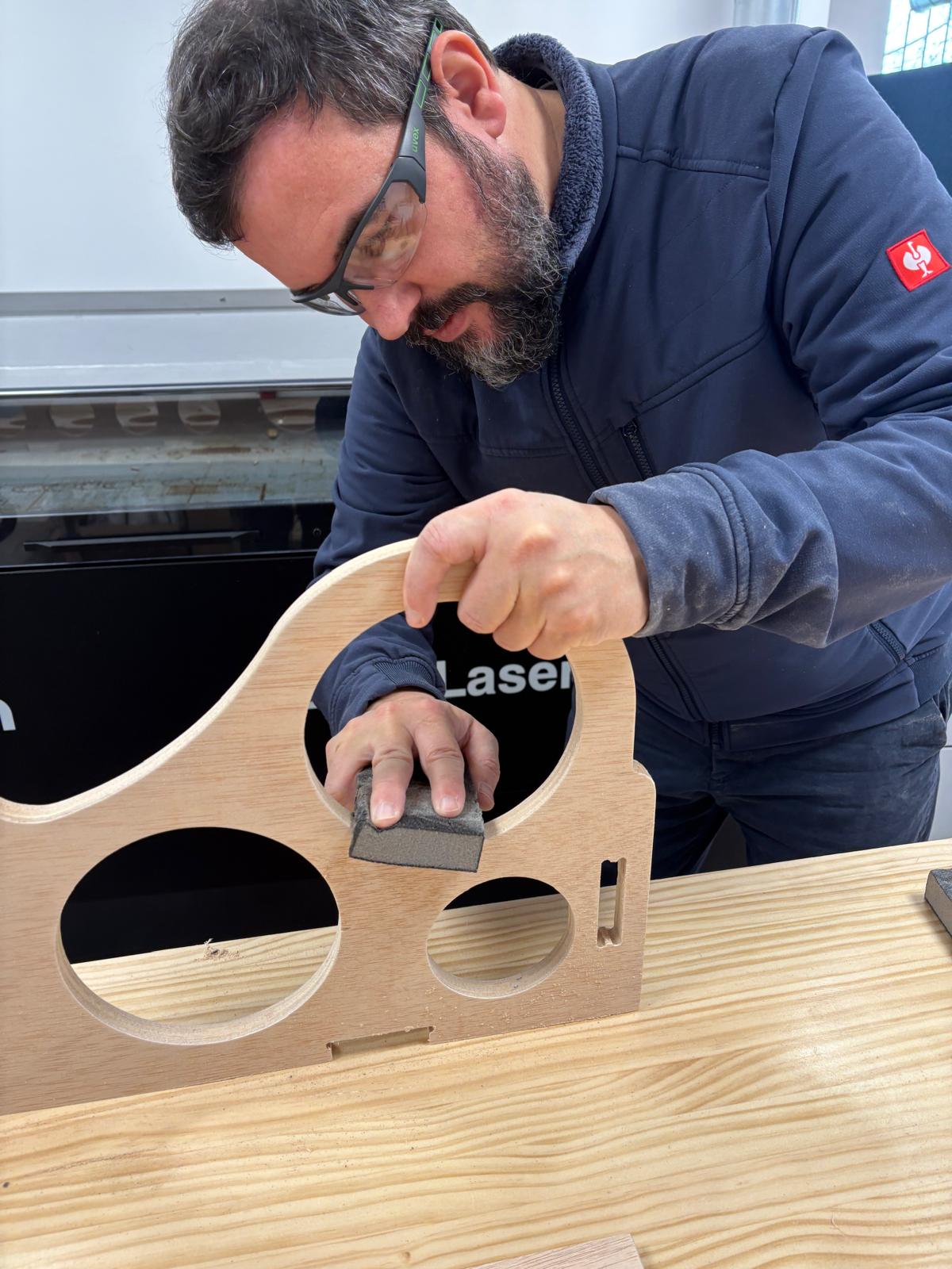
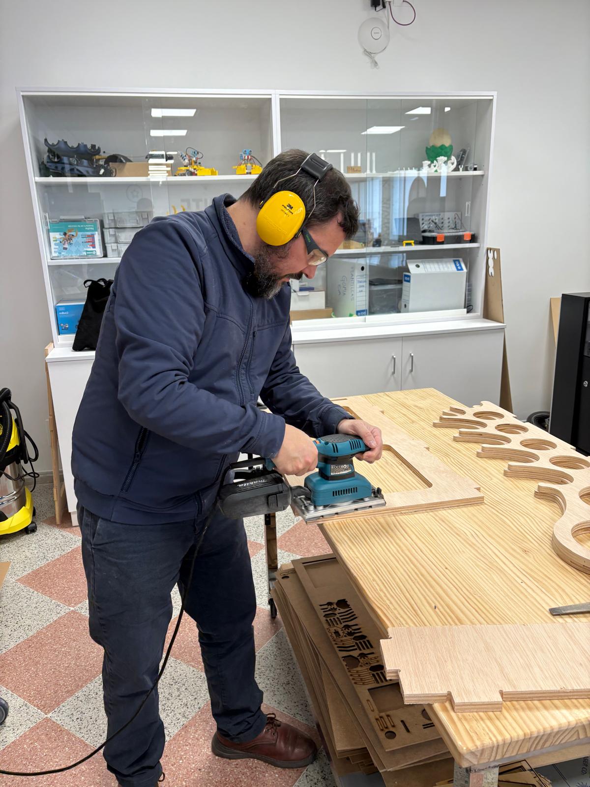
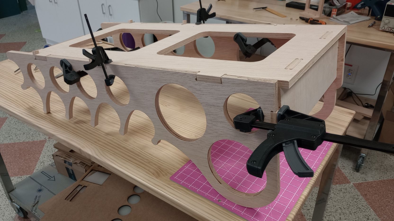
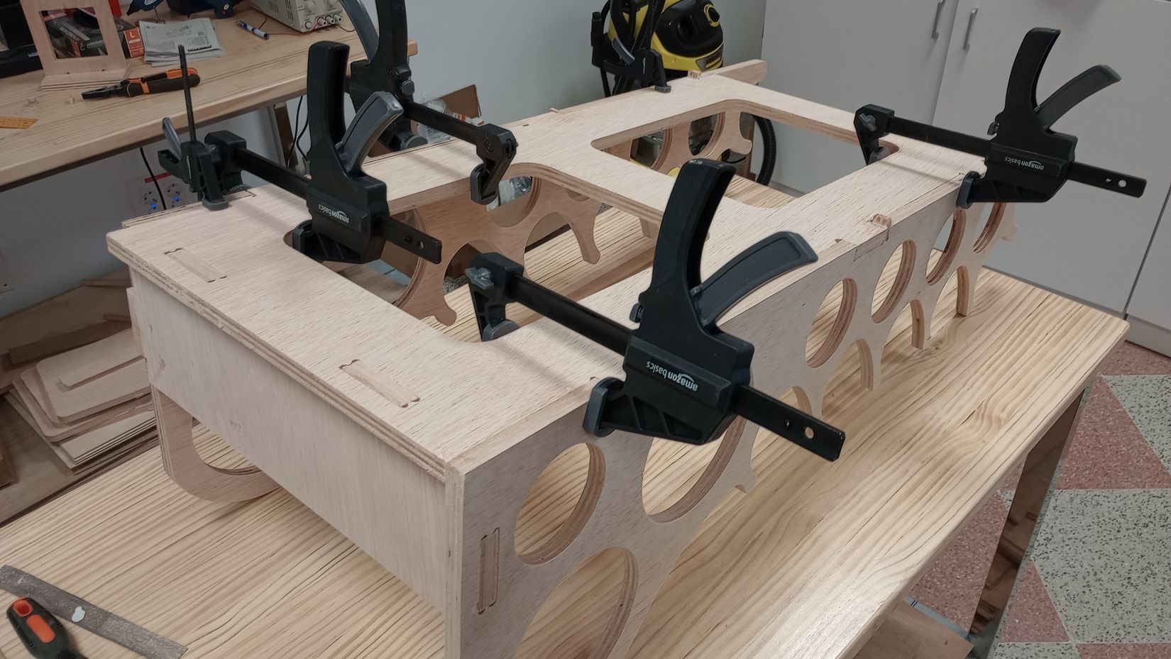
I sand all the parts and then I perform a dry-fit assembly before gluing. This helps me ensure I am clear on the order to assemble and clamp the parts.
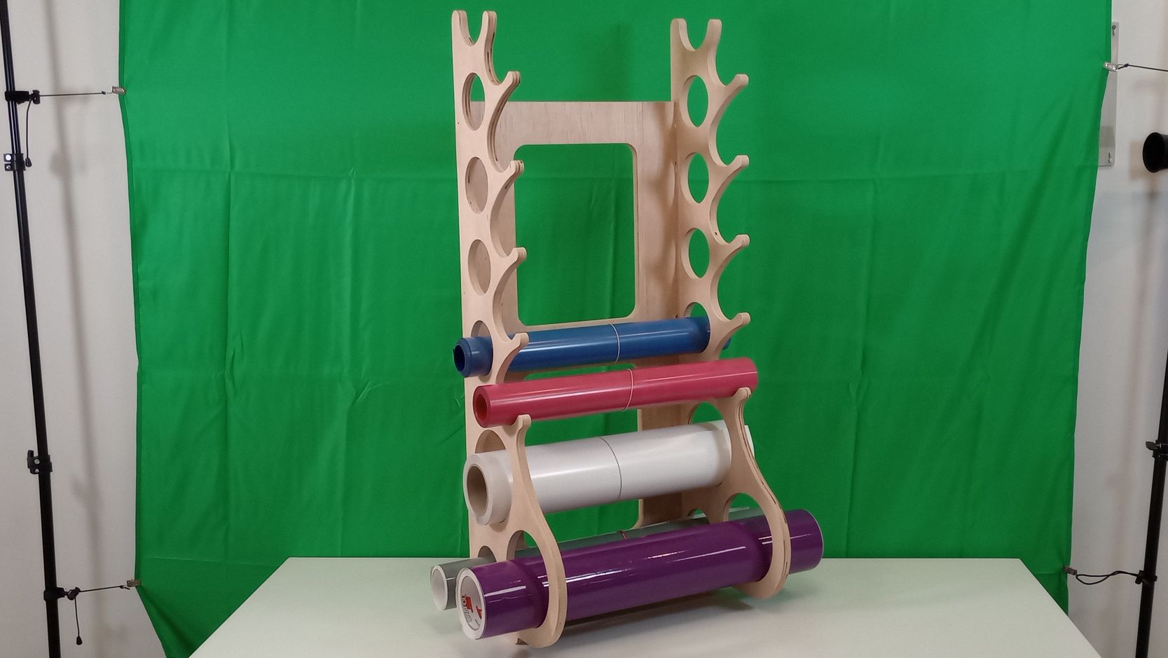
A photo of the vinyl rack mounted on the wall will be coming soon!
WORKFLOW TO MACHINE 3D OBJECTS
The following steps show the exploration of another workflow and the possibility of machining a 3D object from different sides of a stock block.
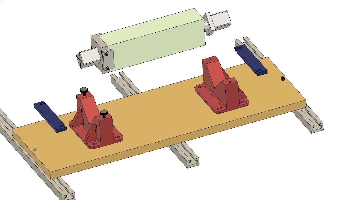
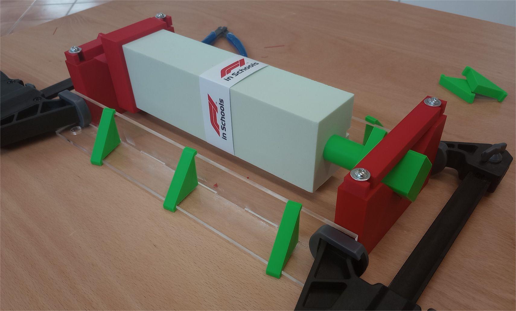
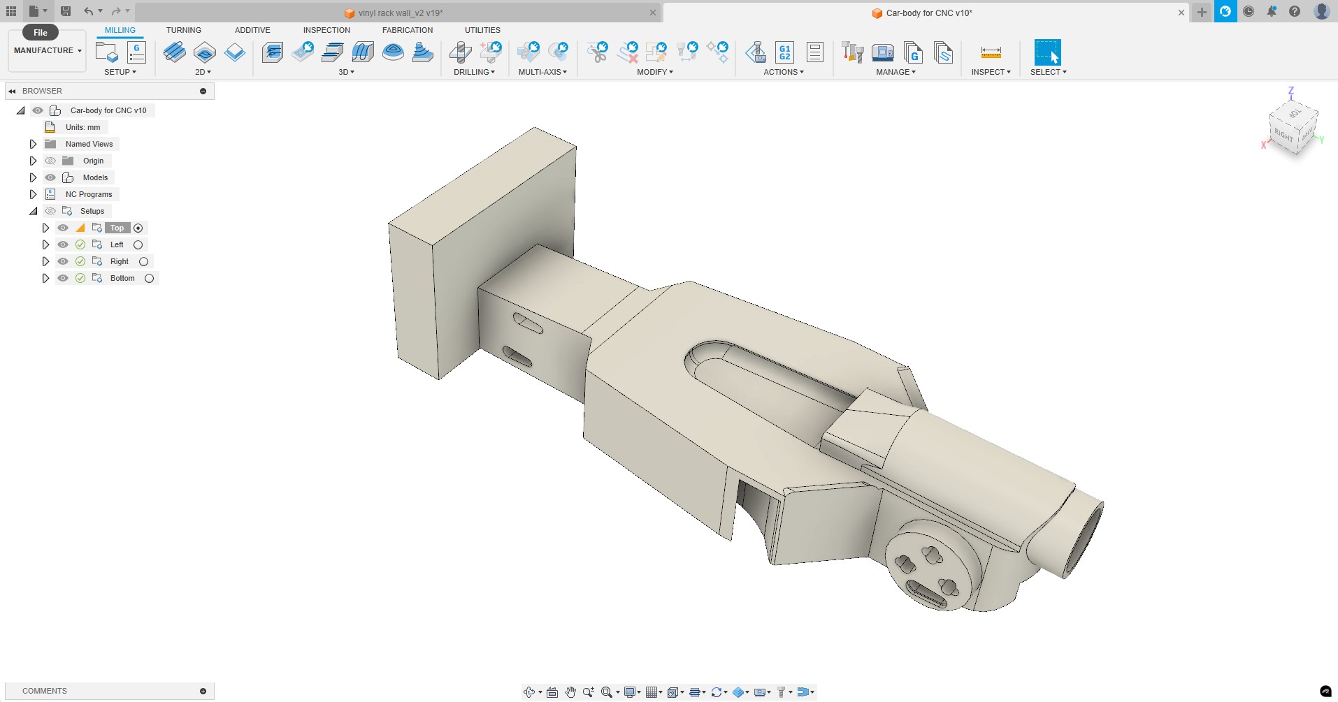
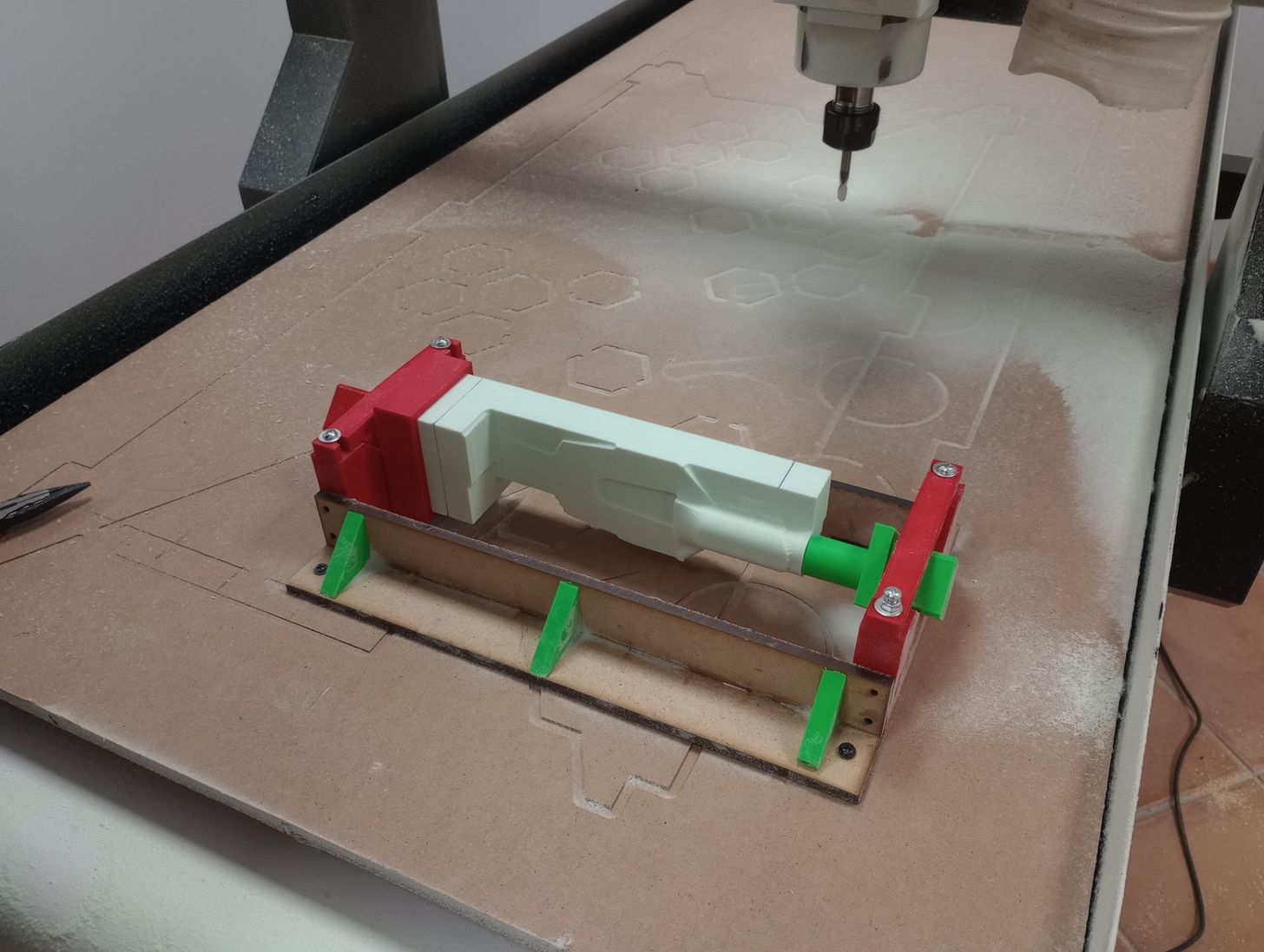
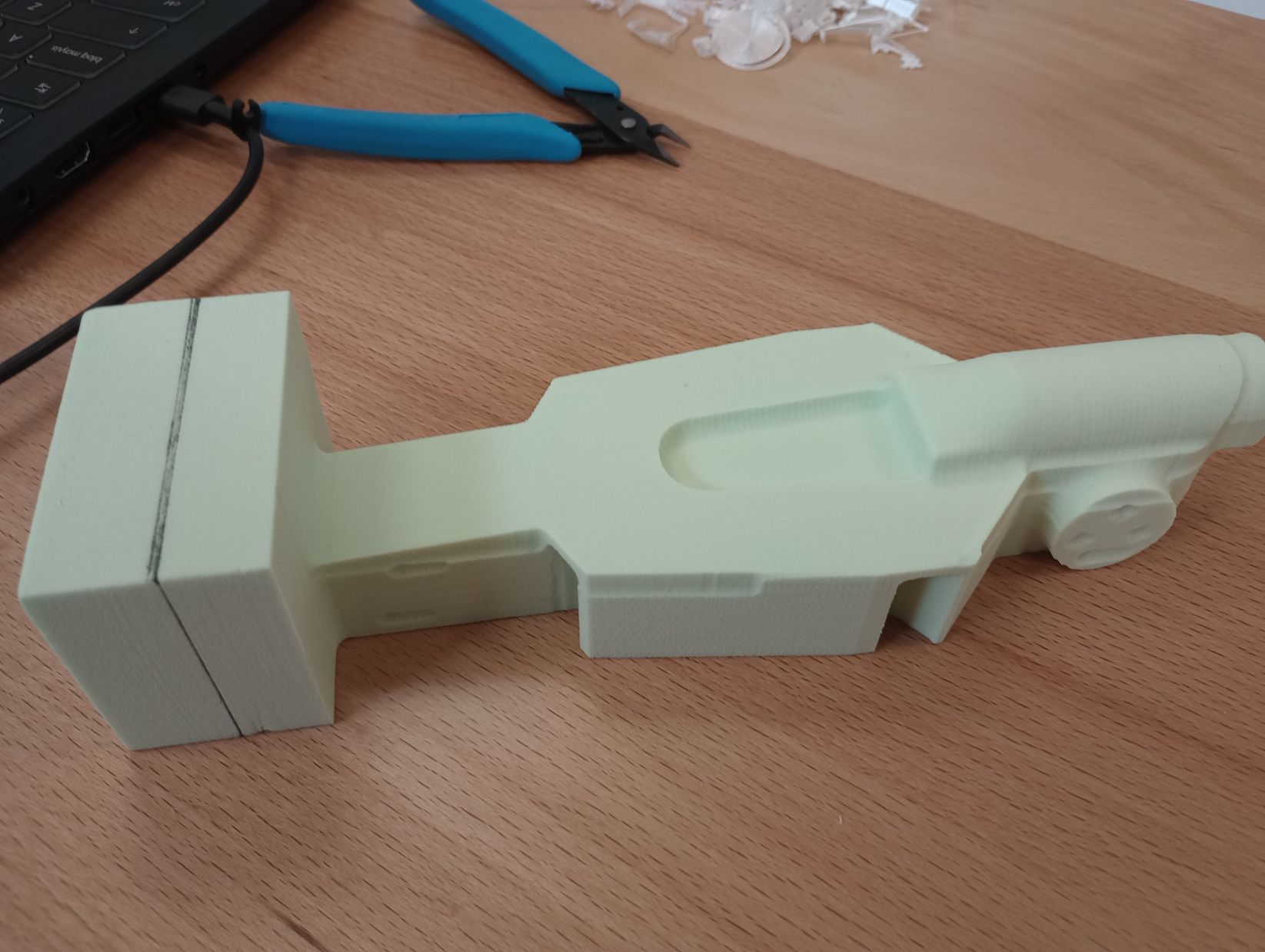
The CNC machine has the capability to work up to 140mm in the Z-axis but it does not have a rotary 4th axis. To be able to machine the body of a small F1 car, I designed and fabricated a jig that will hold a high-density foam block. This jig has been designed to be able to rotate the stock 90 degrees to machine all sides.
I designed the jig in Fusion and fabricated it with 3D printing and laser cutting.
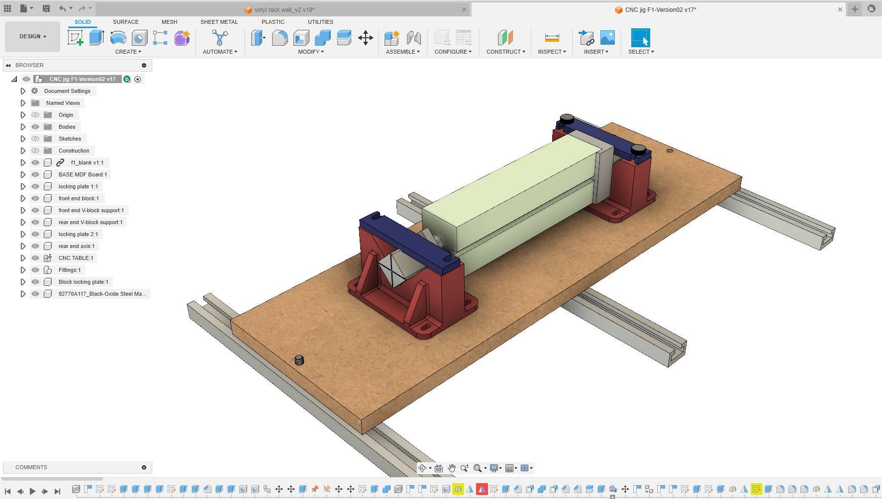
With the design of the car body in Fusion, I use the Manufacture module to generate rough and final toolpaths on each side of the block. I export the toolpaths for each side and send then to the CNC.
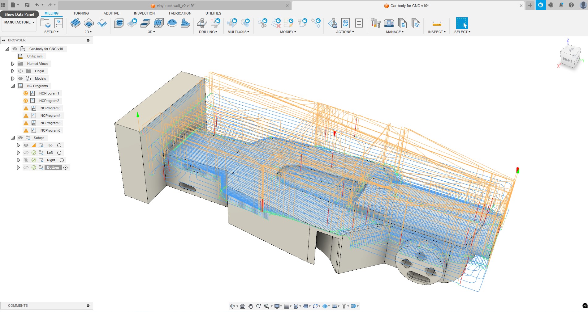
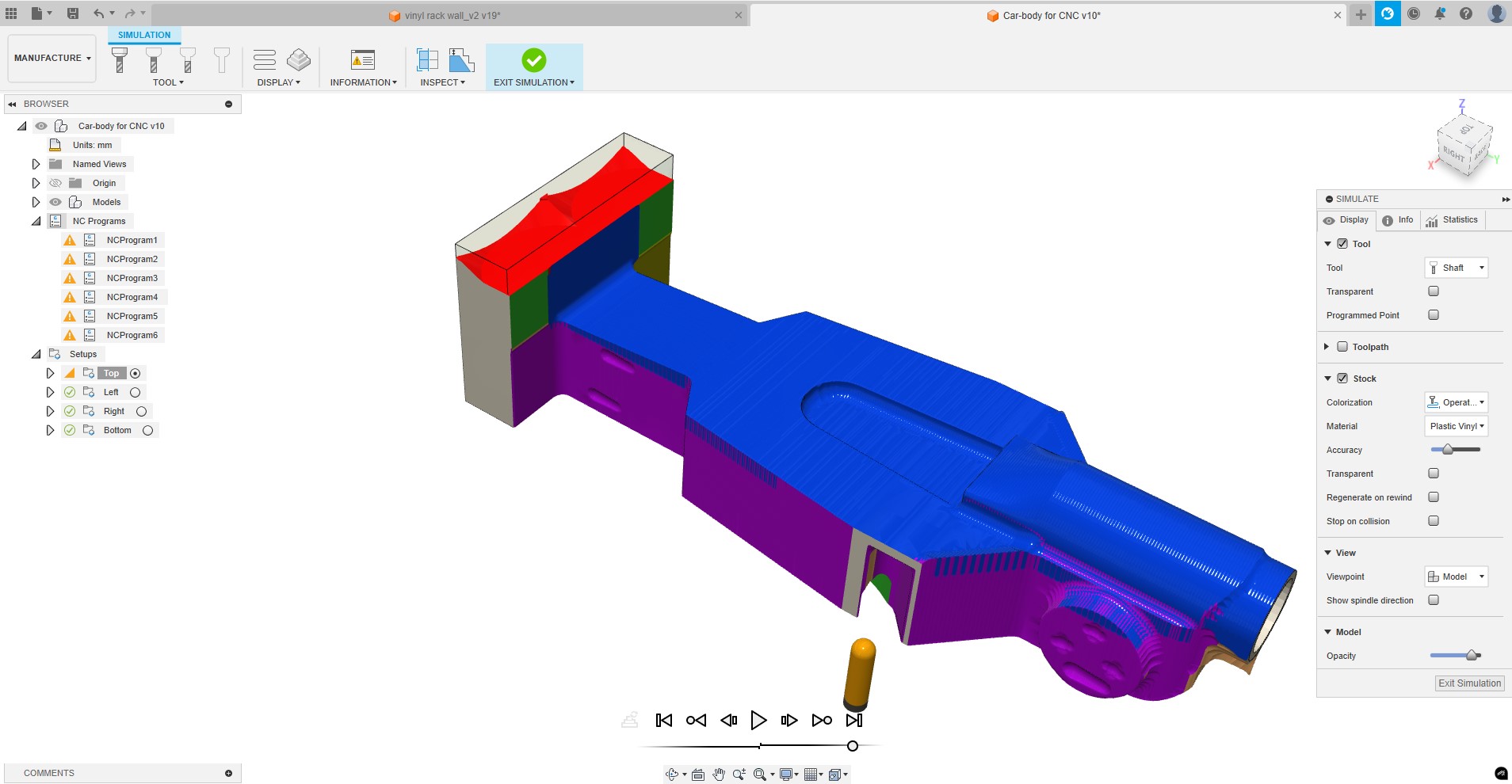
I start running the top toolpaths, and then each side. Between each operation I need to manually rotate the stock and set the origin again.
USEFUL LINKS AND RESOURCES
FILES
CAD drawing test piece: joint_test_piece.dxf
CAD drawing vinyl rack: viny_rack_cnc.dxf
Parametric Fusion 3D model of vinyl rack: vinyl_rack_wall_param.f3d
Fusion 3D model of rotative jig for CNC: 3D_CAD_CNC_rotative_jig.zip
Top