FINAL PROJECT DEVELOPMENT
This page will be used to showcase the development of my final project.
Table of Contents
- PROJECT IDEA: DUAL-AXIS SOLAR TRACKER
- INITIAL CAD MODEL OF FINAL PROJECT
- DETAIL CAD MODEL OF FINAL PROJECT
- FINAL PROJECT PLANNING
- 3D PRINTING
- CNC
- ELECTRONICS
- FIRMWARE
- APP FOR BLE CONTROL
- BILL OF MATERIALS
- USEFUL LINKS AND RESOURCES
- FILES
PROJECT IDEA: DUAL-AXIS SOLAR TRACKER
The final project started from an initial proposal that I developed with several sketches and notes to anticipate the main challenges, such as the mechanical actuation needed to rotate and tilt the solar panel and the types of sensors I could use. The FINAL PROJECT PROPOSAL page contains a detailed description of this initial concept.
At that stage there were still many open questions and unknowns, but I had several weeks of learning and hands-on work ahead to turn the idea into a working system. In the following sections, I document the steps I followed to complete this project, from the first concepts to the final prototype and its evaluation.
INITIAL CAD MODEL OF FINAL PROJECT
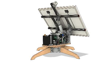
A natural progression from the initial sketches was to develop more defined geometry and layout. This happened during Week 2: Computer-Aided Design, where I created a rough CAD model of the solar tracker.
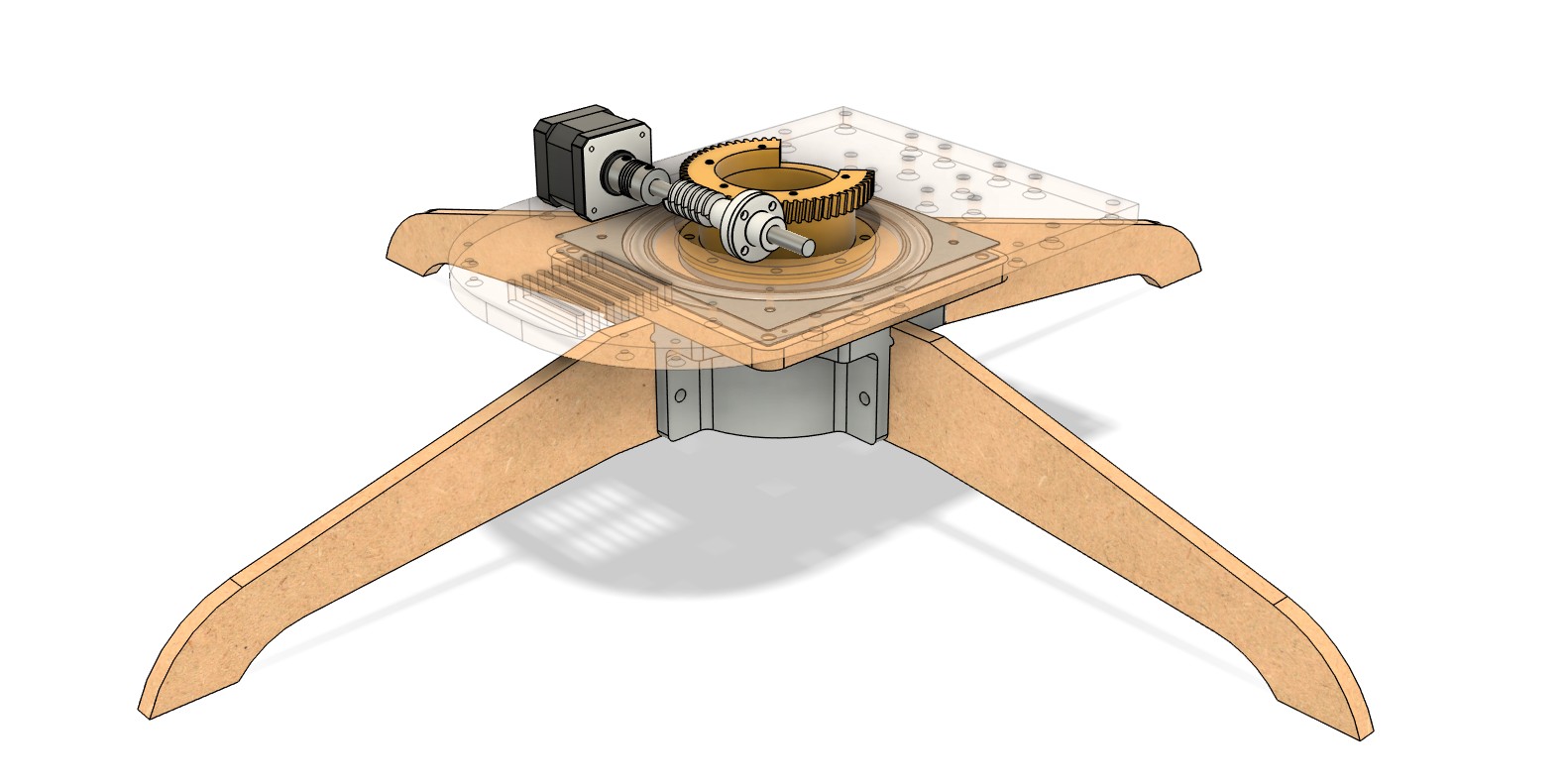
Even though this first model did not include much detail, it worked as a proof of concept, showing the main elements of the system: the solar panel assembly, the linear actuator, the enclosure, the gear train, and the base with legs.The following images show different views of this initial CAD model.
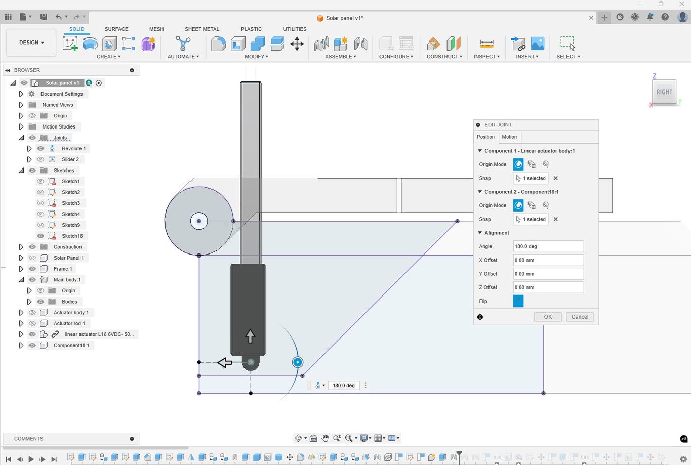
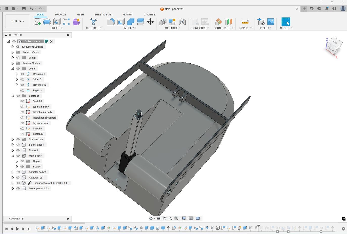
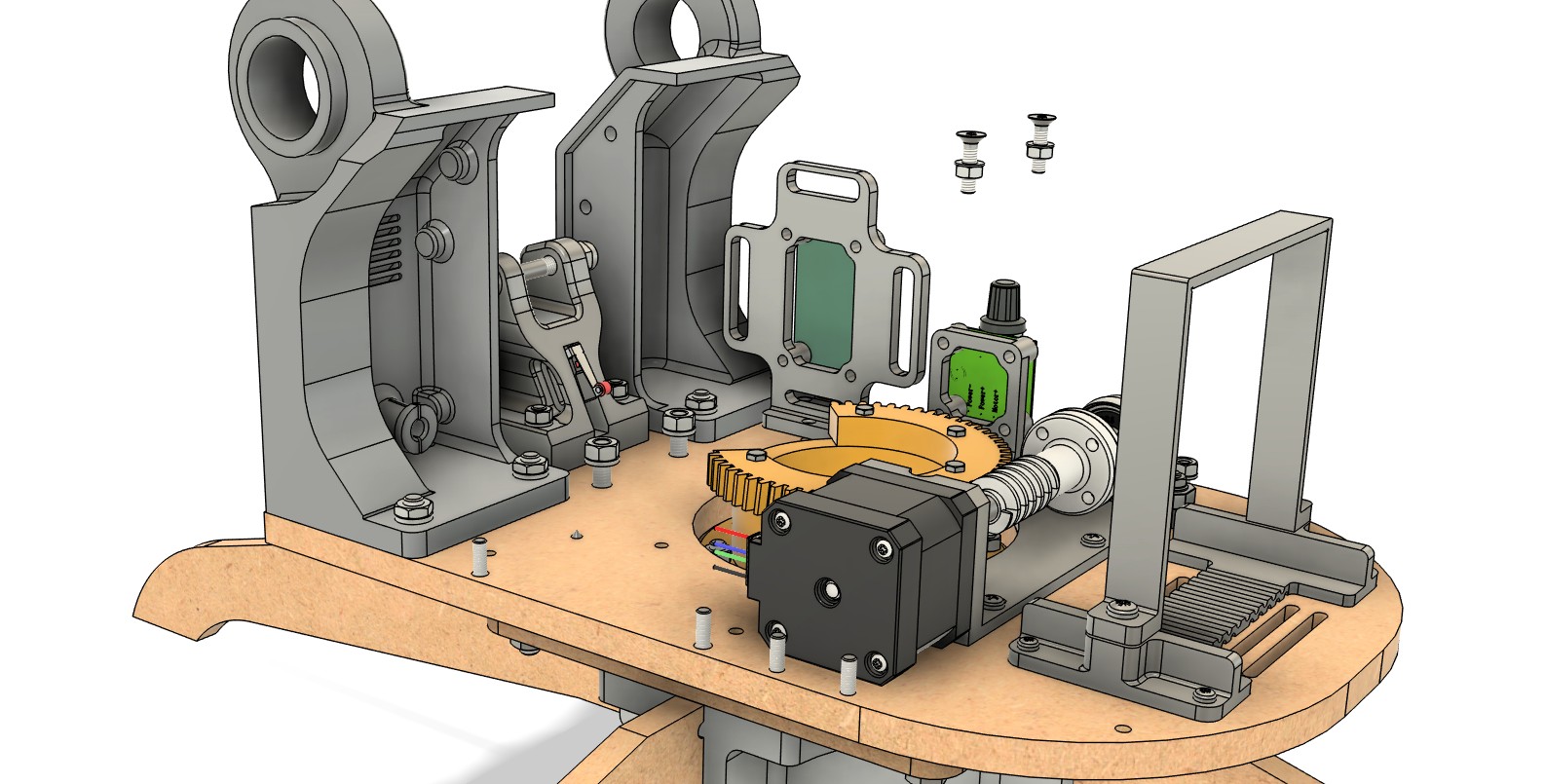
DETAILED CAD MODEL OF FINAL PROJECT
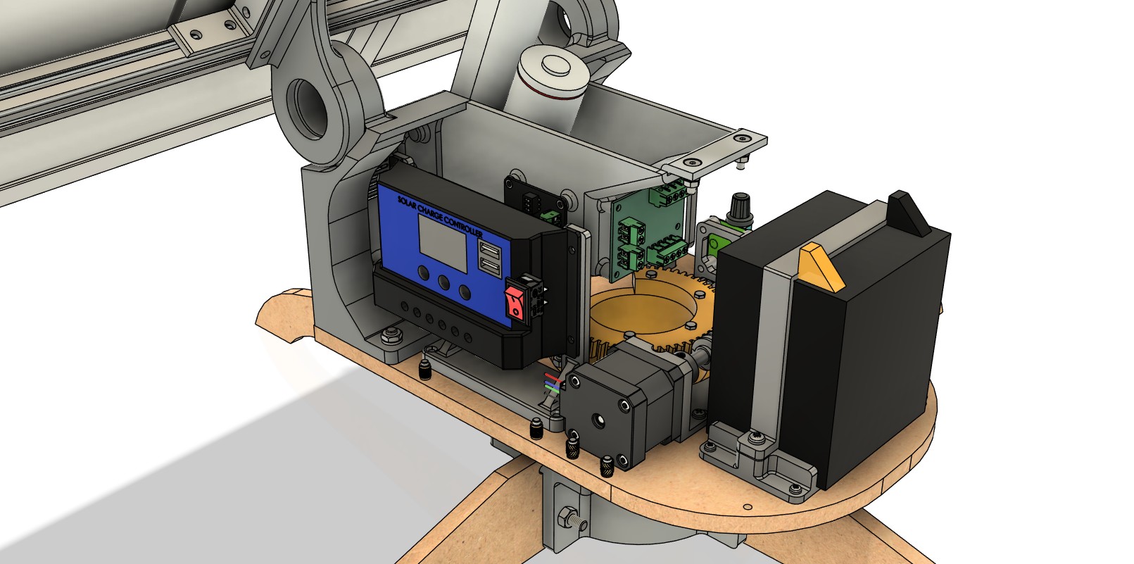
During the following weeks, the project progressed as I started selecting and purchasing components and making decisions about how to assemble and fabricate each part.
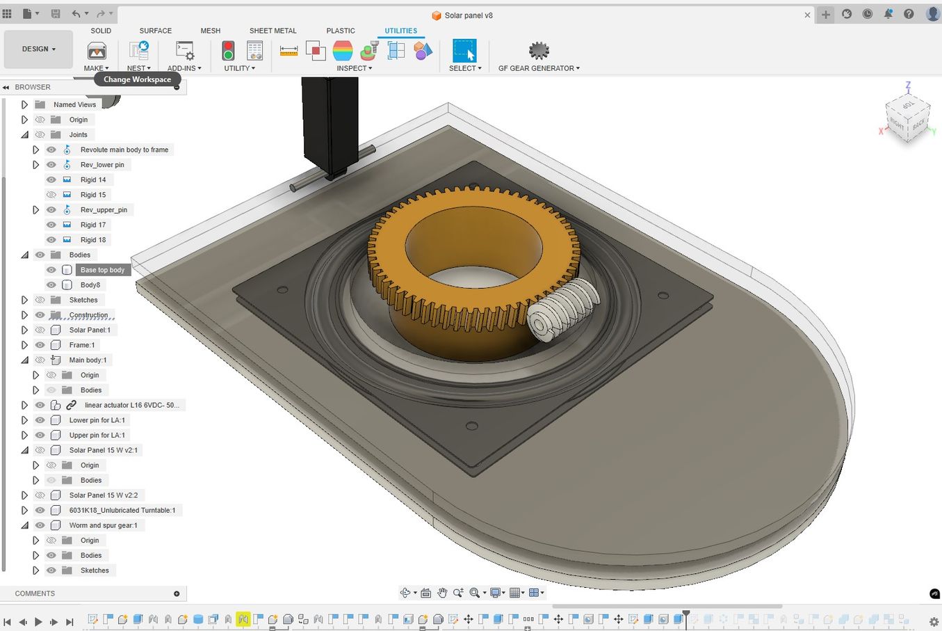
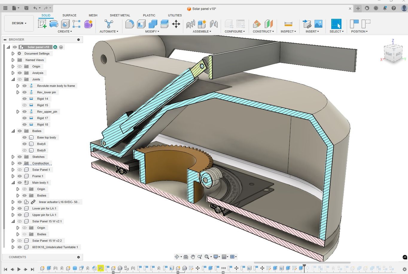
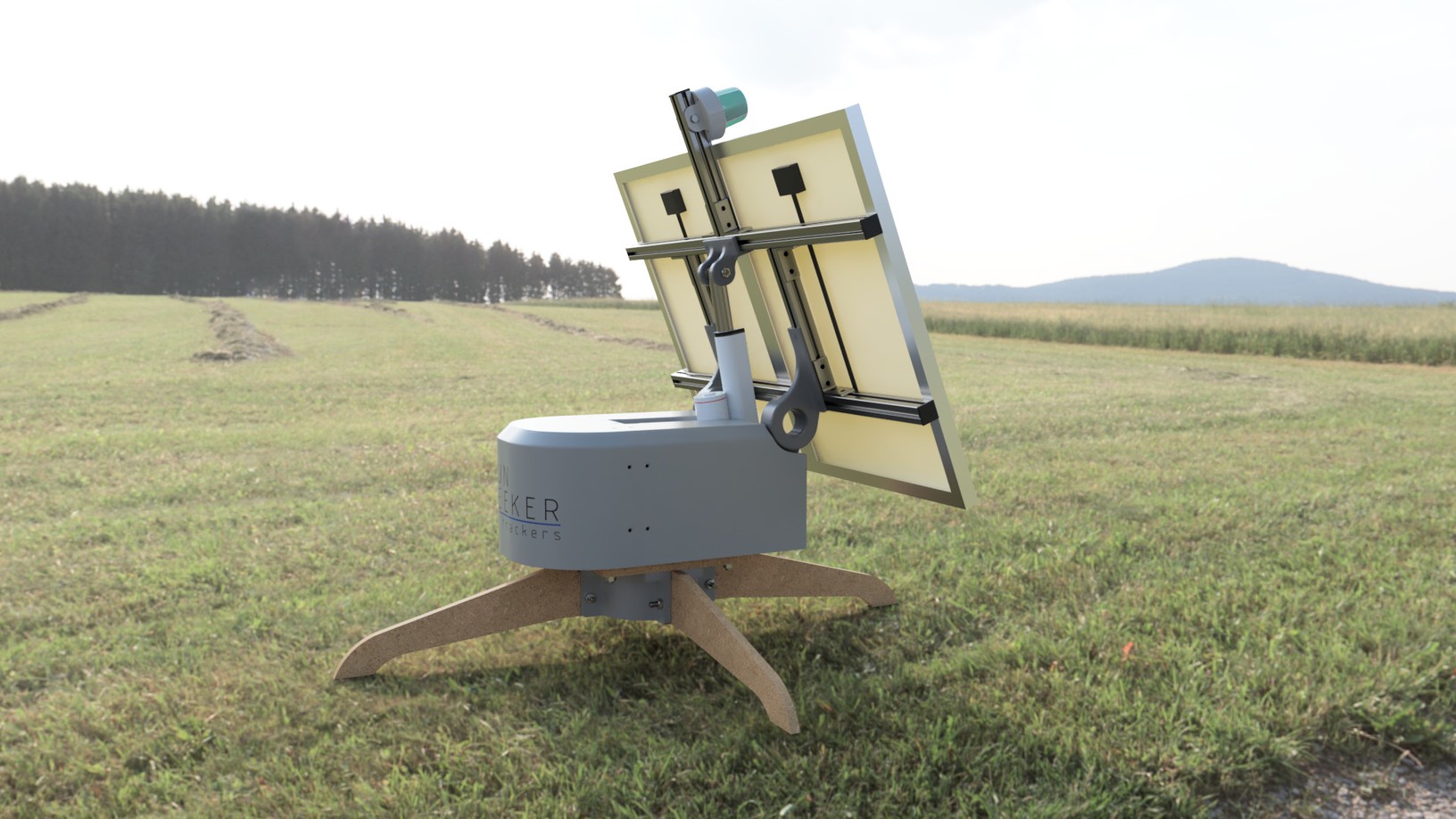
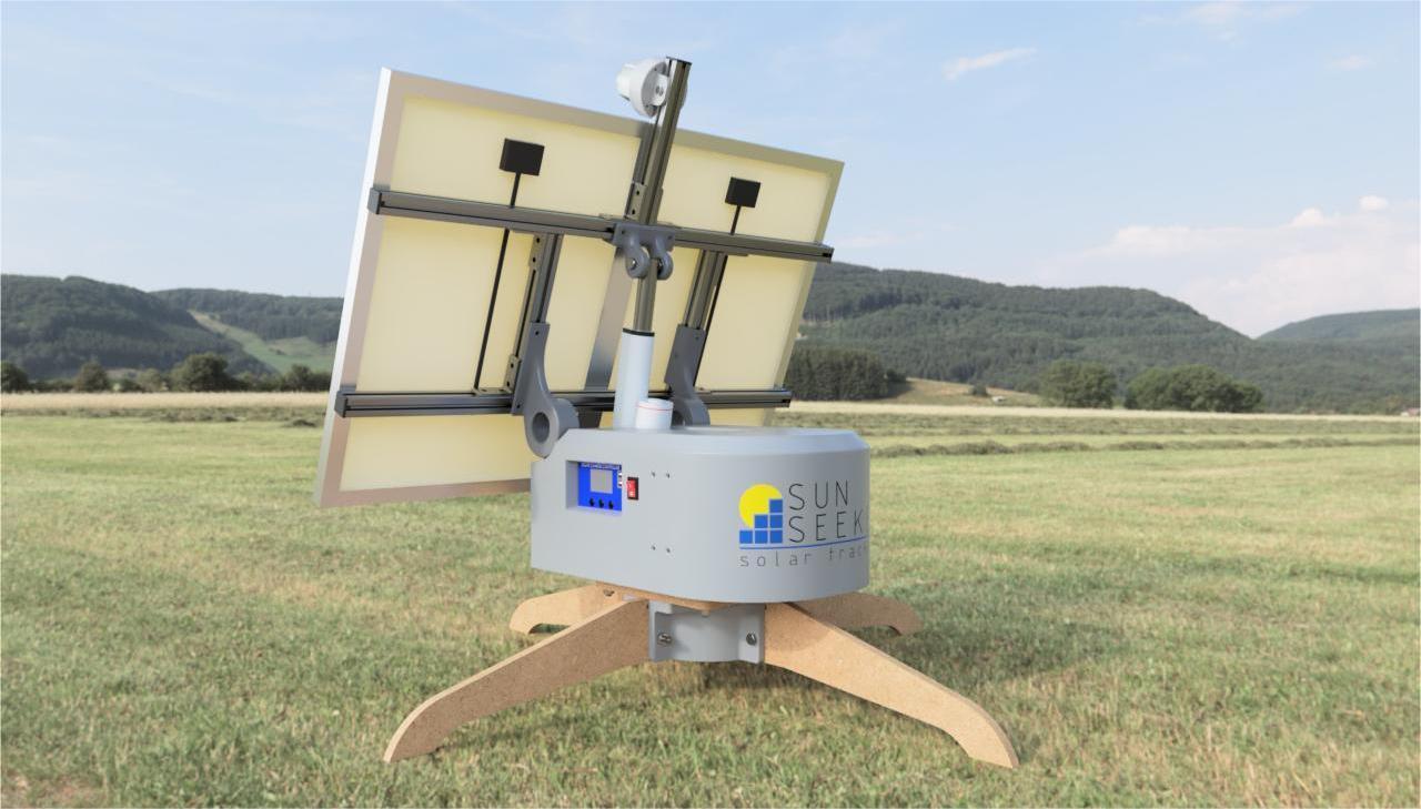
Once I had key elements such as the solar panels and the linear actuator, I created detailed CAD models of these parts and integrated them into a full assembly of the product.
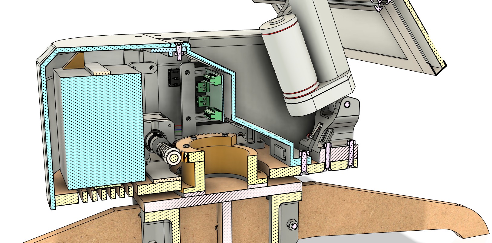
The level of detail went down to modelling fittings and fasteners with accurate dimensions to ensure that parts could be assembled correctly, avoid clashes, and achieve proper integration of all systems. Creating such a detailed model took many hours, but it paid off: the hardware integration worked well, and I saved time and material by not having to redesign and fabricate parts multiple times.
Top
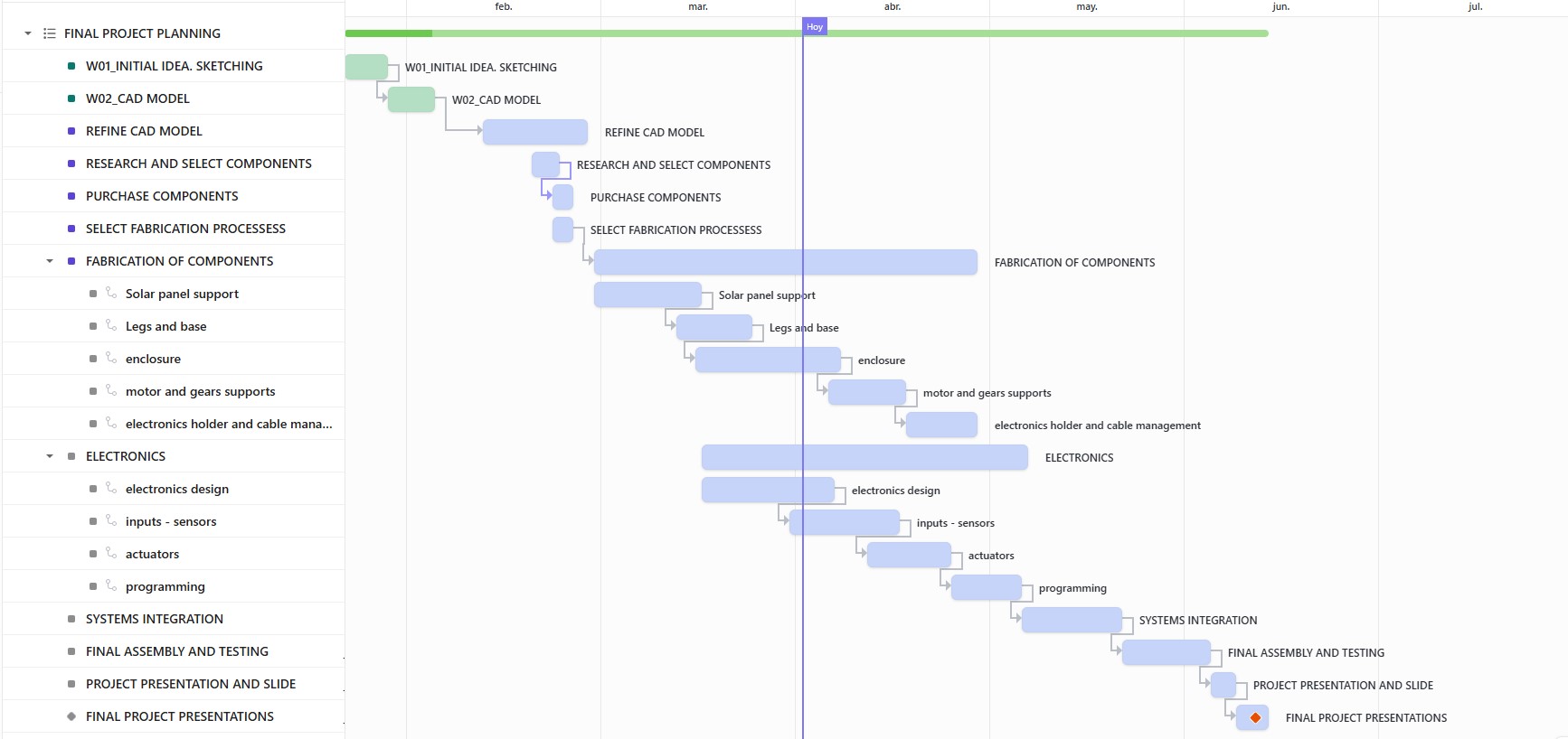
FINAL PROJECT PLANNING
On 13/02/2025 I created a initial Gantt diagram with the main tasks and estimated duration. I'll be adding more tasks and updating dates as needed to reflect the project development.
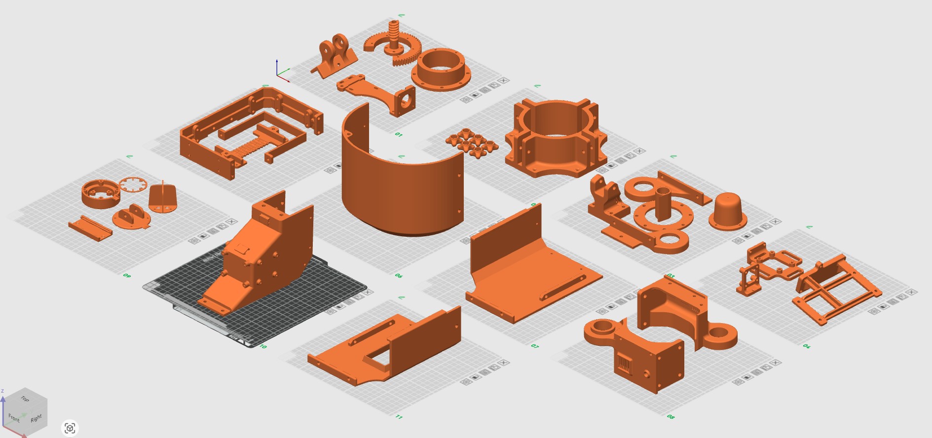
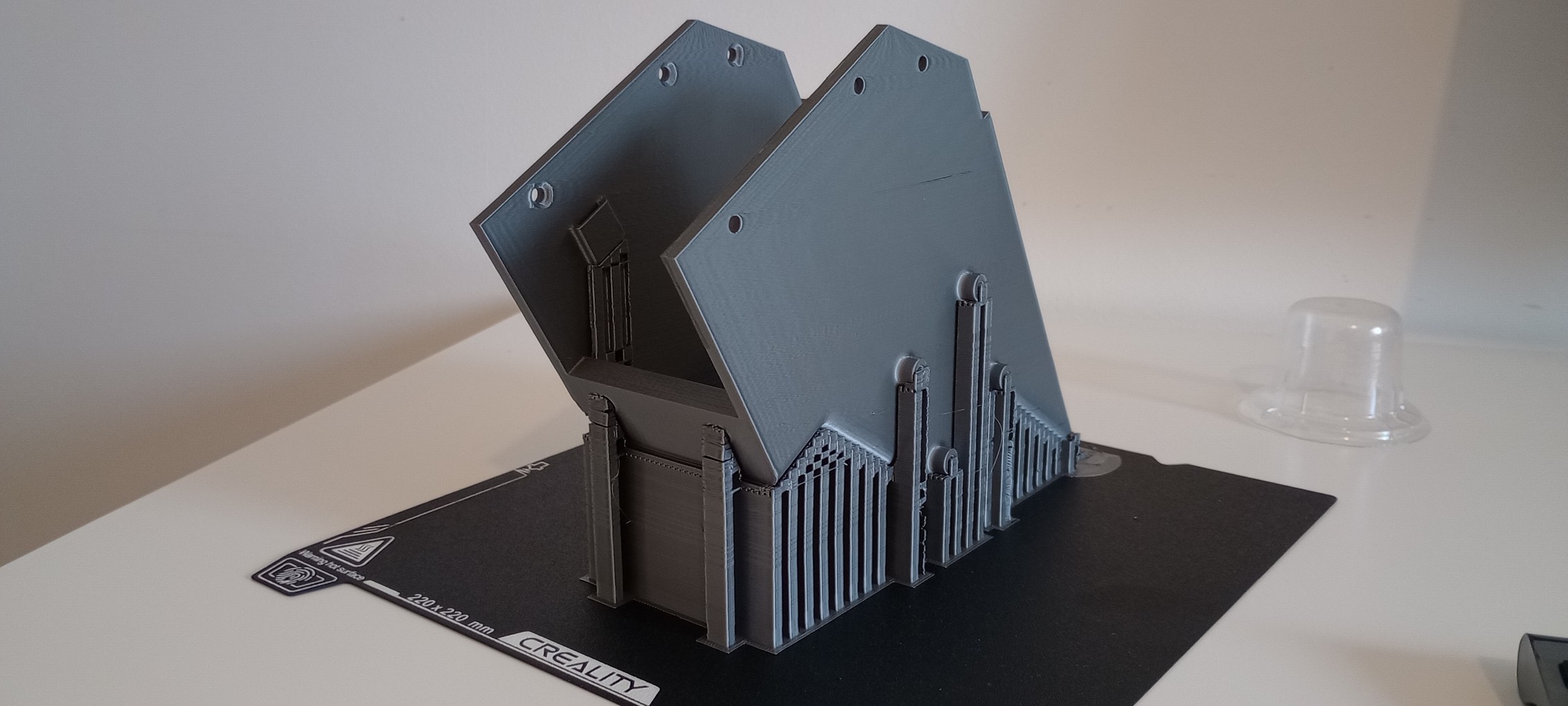
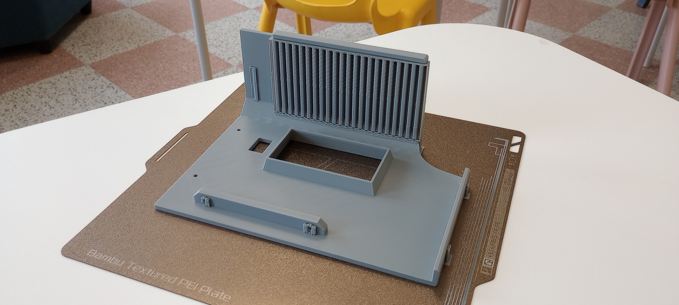
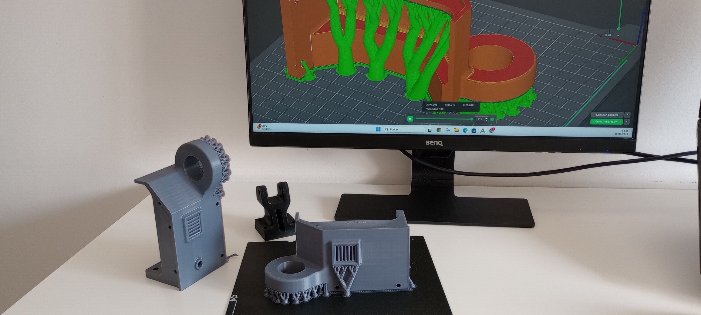
3D PRINTING
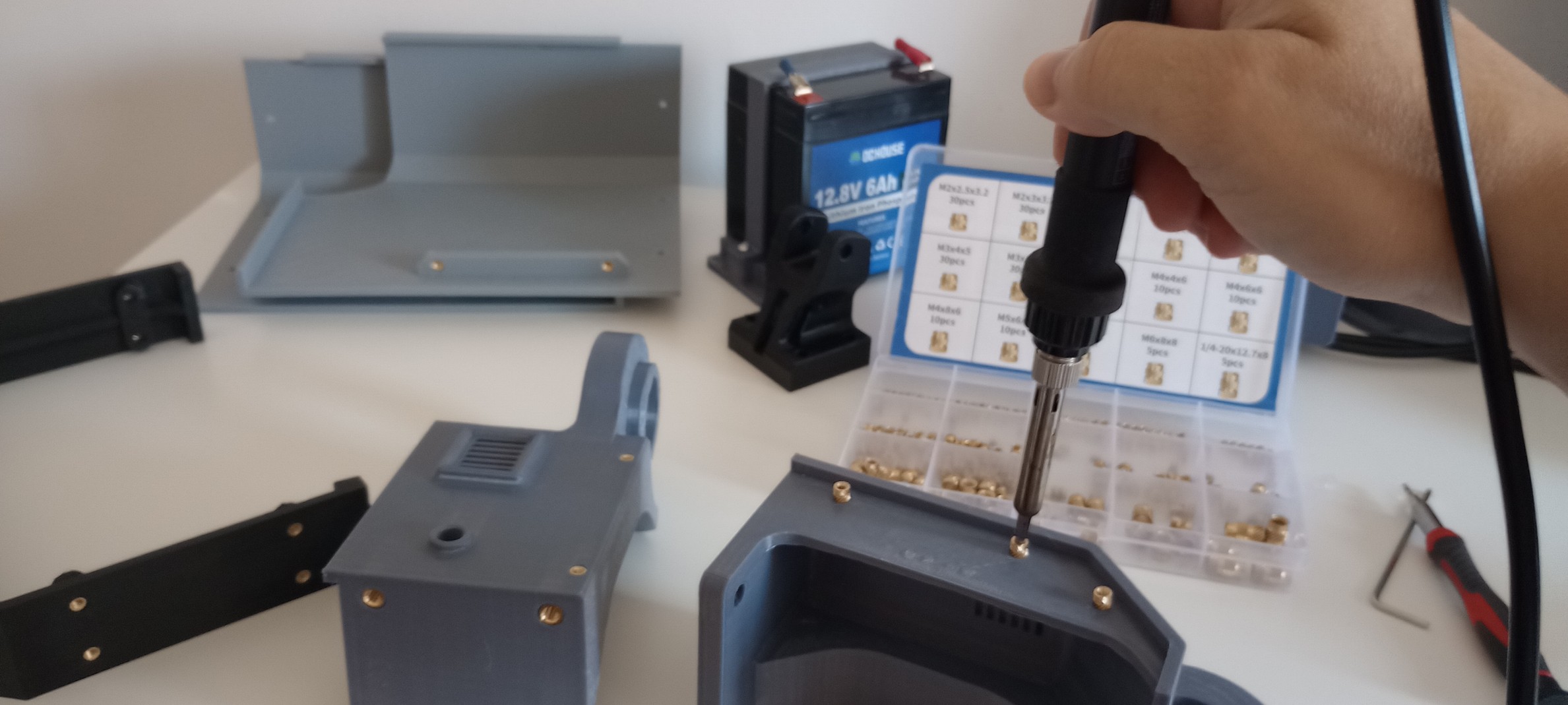
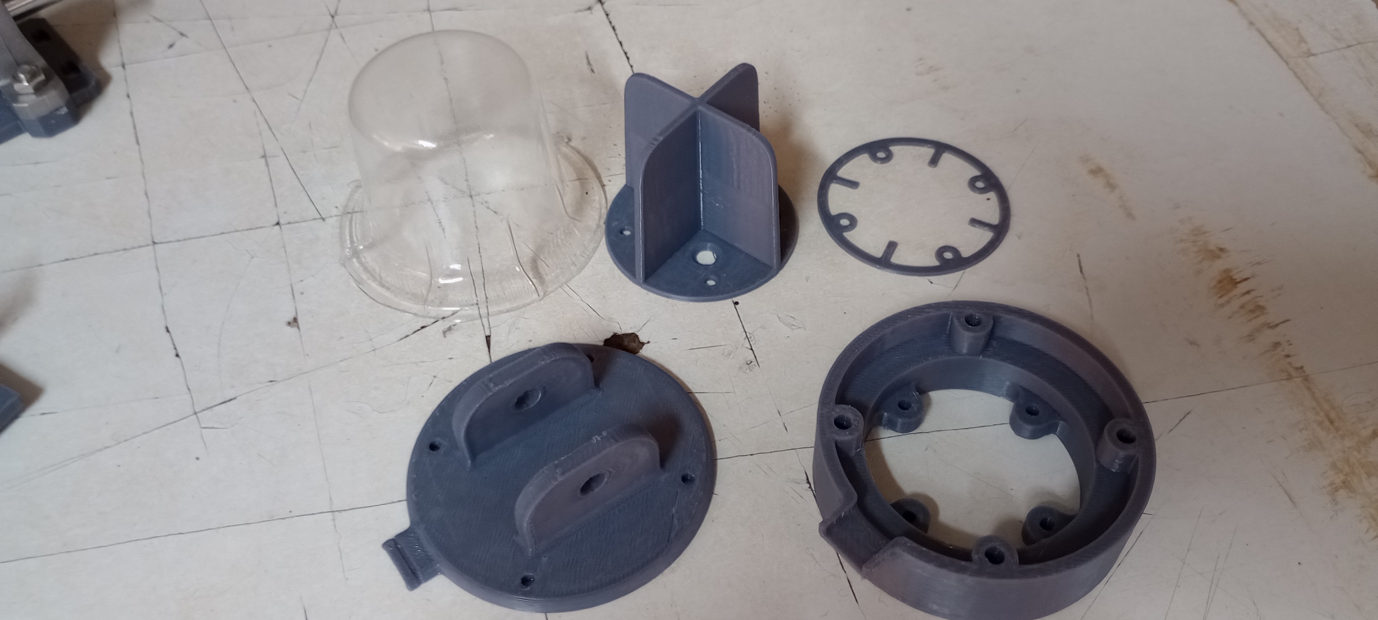
3D printing was a key fabrication process for many parts of this project. Designing with this process in mind allowed me to create complex components, such as hinges integrated into the enclosure, with thick walls and brackets to transmit the loads from the solar panels to the body of the enclosure. These parts also had to connect to other sections of the enclosure and to the base, so they included threaded heat inserts, holes for fittings, integrated vents, and cable-routing holes.
All parts were 3D printed in good-quality PETG filament, which offers better properties for outdoor applications than PLA. To keep a consistent aesthetic, I used mainly grey filament, especially for external or visible components.
I only had to redesign one part that broke: the lugs connecting the solar panel to the linear actuator. Apart from that, all parts were successfully printed while trying to minimise the use of supports to reduce waste and printing time.
CNC
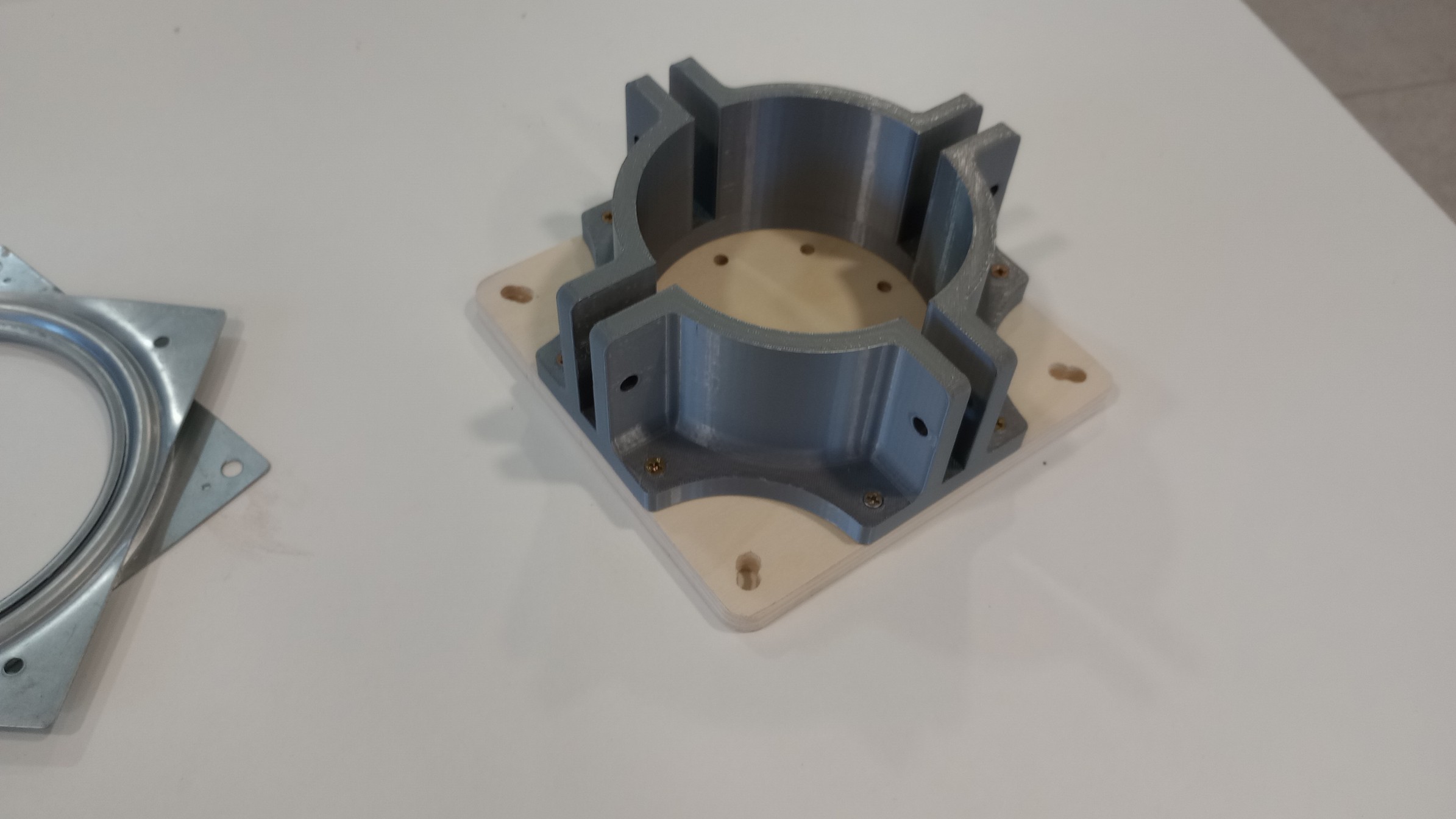
CNC cutting was the process I used to fabricate the base and legs of the tracker. I machined them from a 400x600x10 mm plywood board. In addition to cutting the base profiles, I included the bolt holes that secure the enclosure and internal components. Doing this ensured the precision and alignment required for parts such as the helical gear.
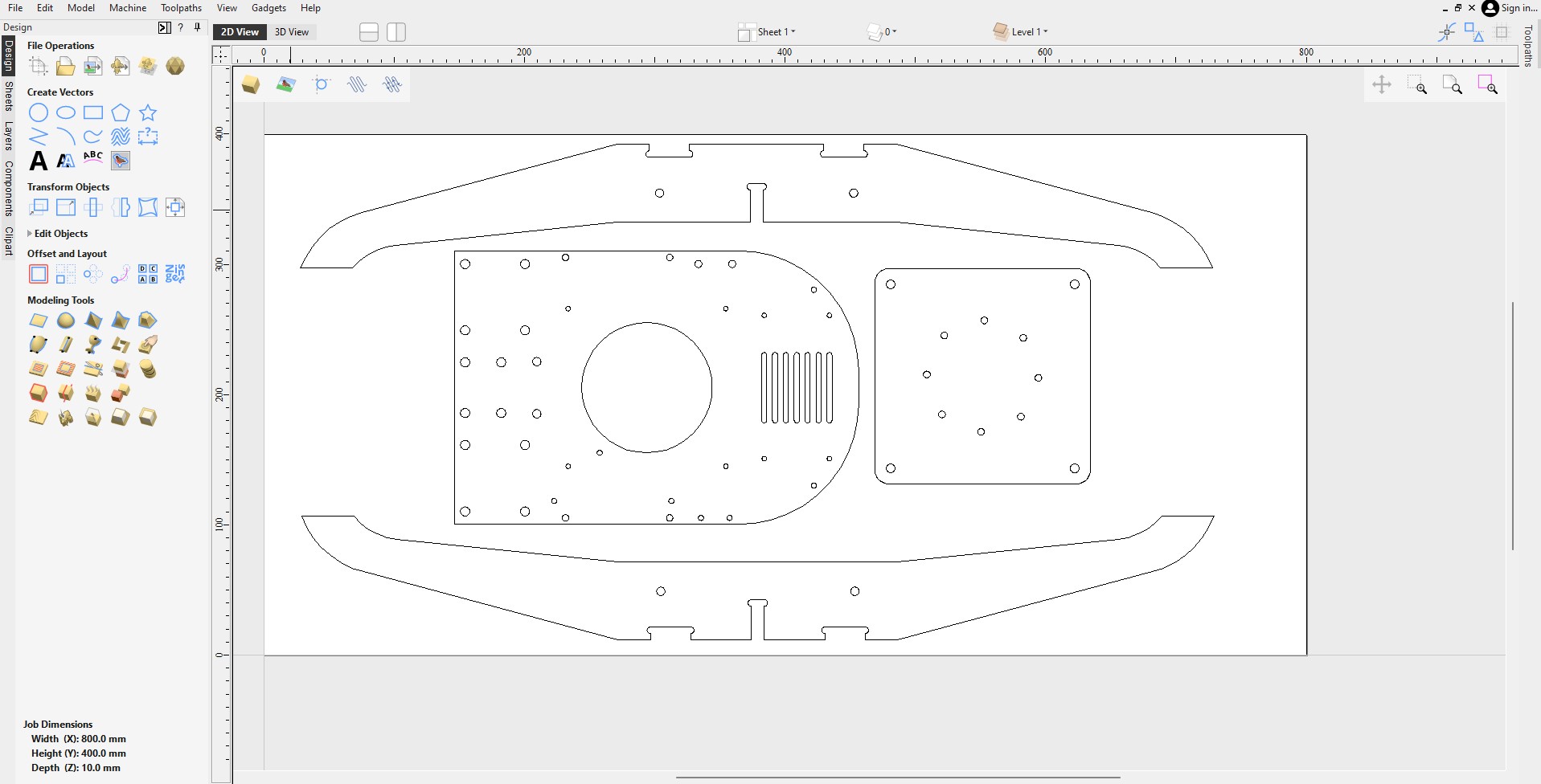
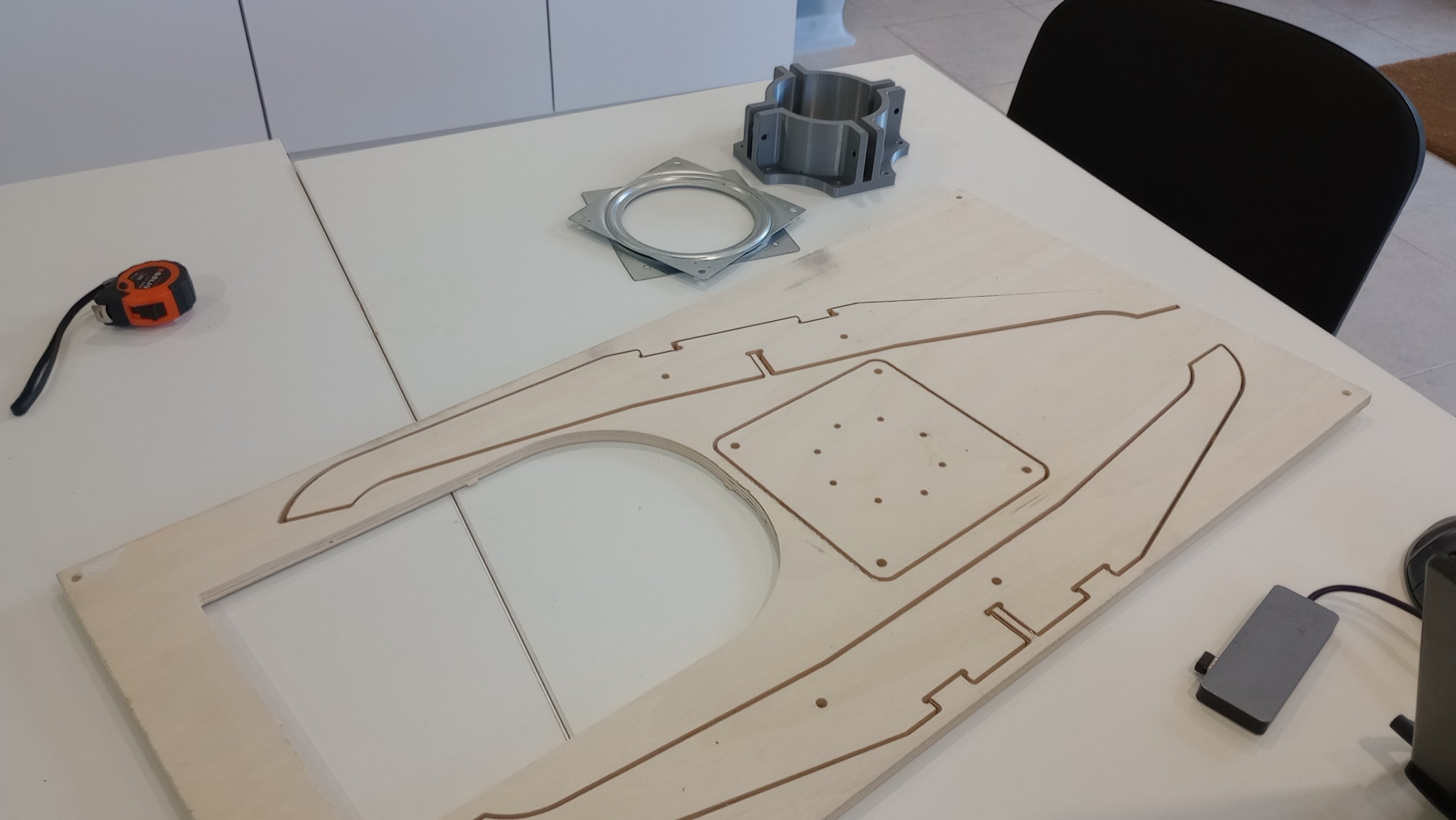
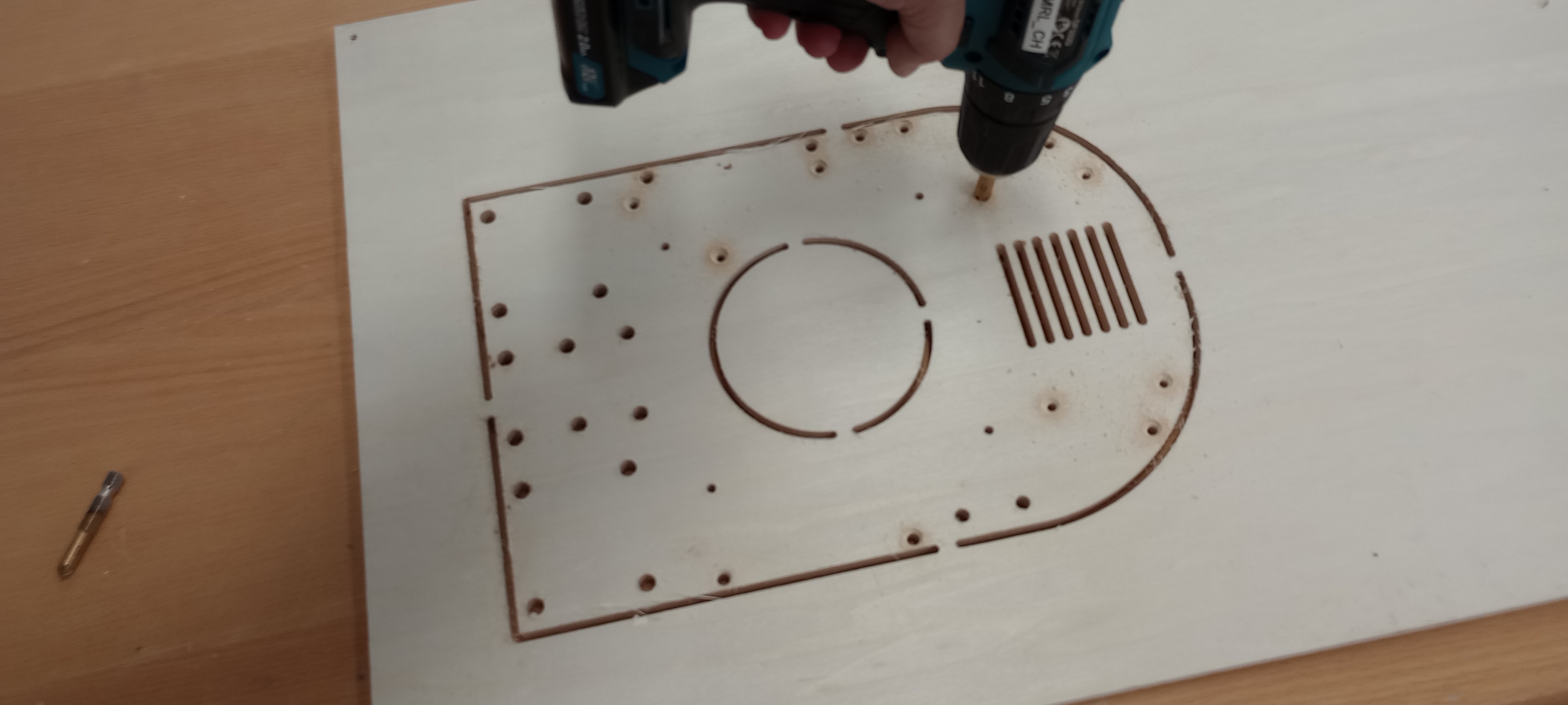
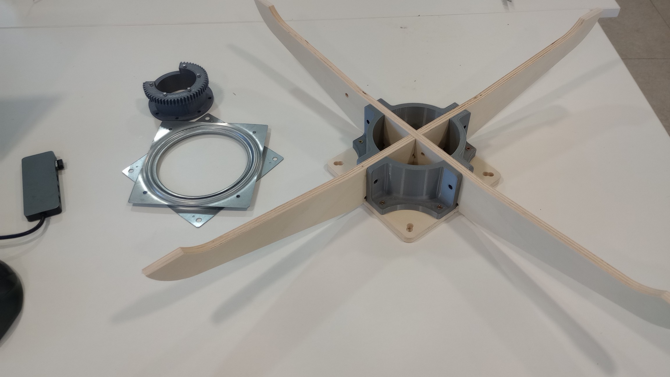
The legs were designed as interlocking pieces that slot together and fit into a 3D-printed connector that integrates the legs with the base.
Top
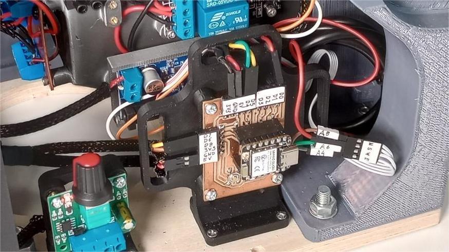
ELECTRONICS
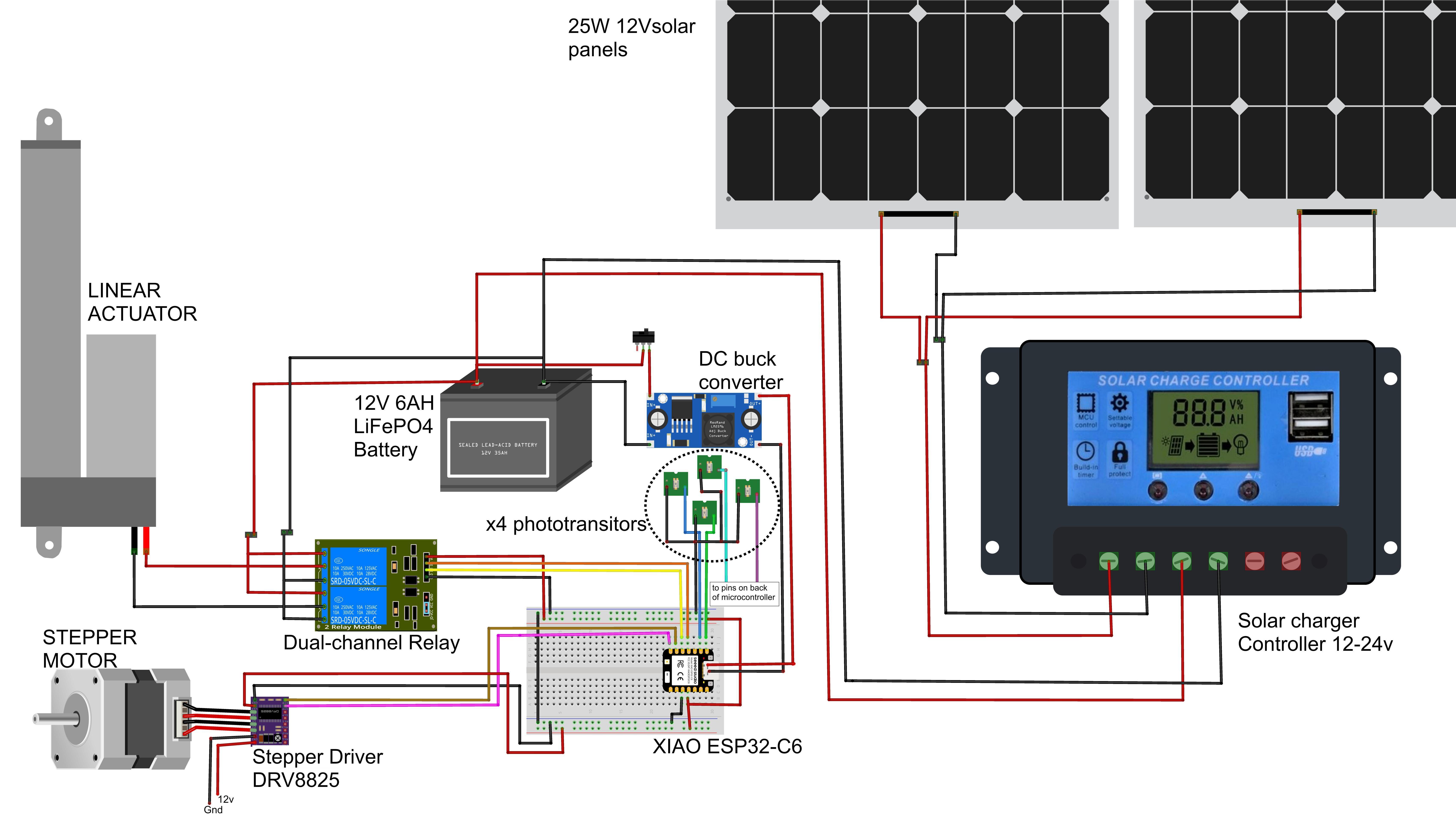
The electronics for the dual-axis tracker are built around a 12 V system powered by the PV panels and battery. The wiring diagram is organized into three main blocks:
- Power path: PV panels feed a 12 V solar charge controller that manages charging of a 12 V LiFePO4 battery. The battery then supplies power to a 12 V power distribution PCB.
- Control electronics: A 12 V to 5 V DC buck converter powers the XIAO ESP32-C6 microcontroller board and the low-voltage sensors.
- Actuators and sensors: A stepper motor for azimuth, a linear actuator for tilt, and a phototransistor sensor array for sun tracking.
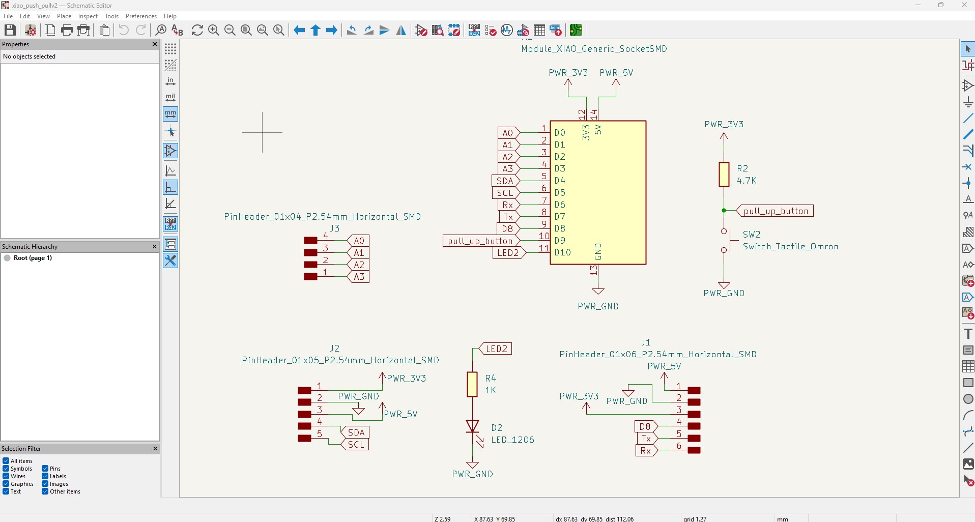
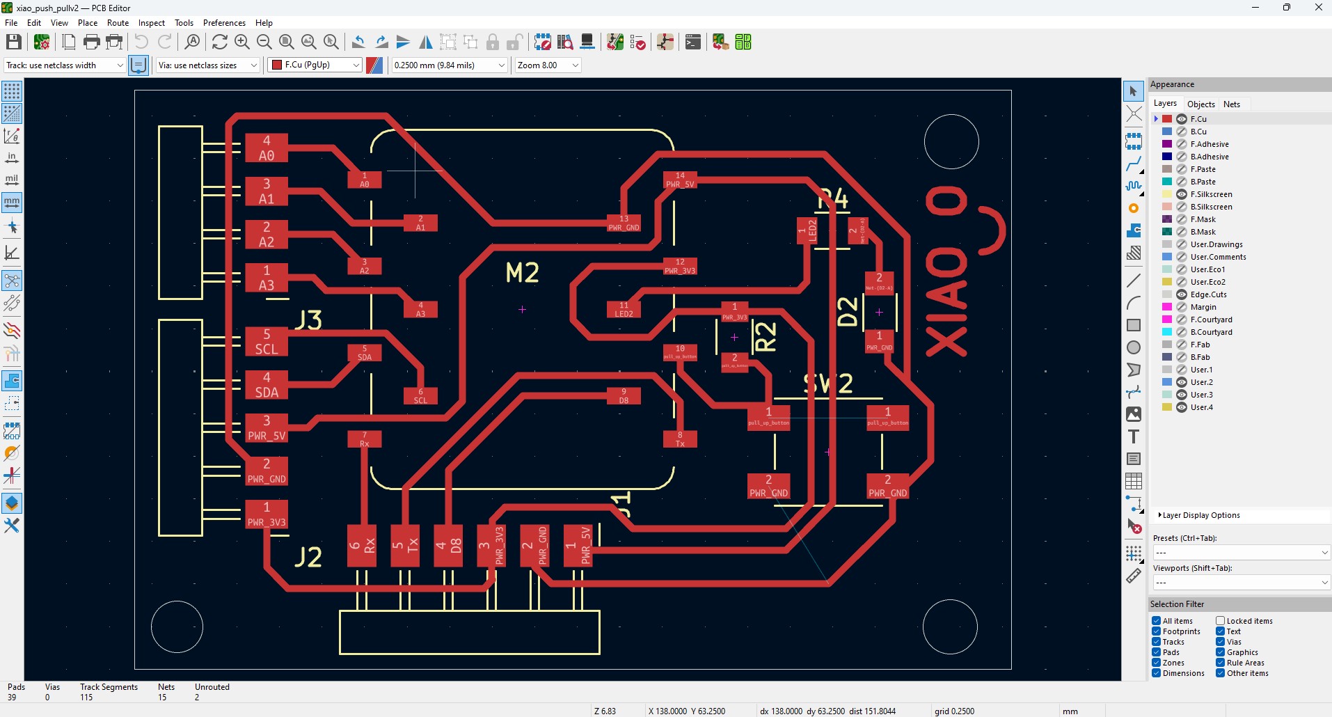
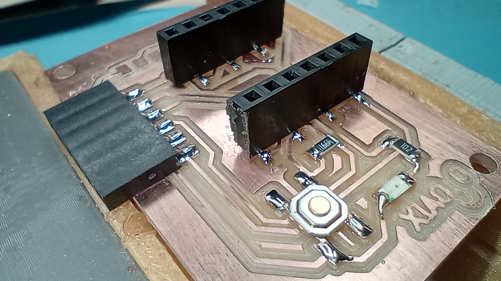
MICROCONTROLLER BOARD
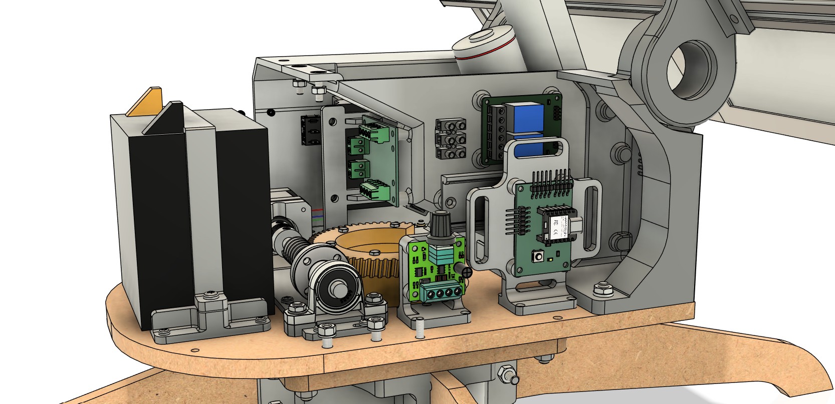
For control I used a Seeed Studio XIAO ESP32-C6 module mounted on a custom PCB. The goal of this board was to provide clean, labeled connections between the XIAO and all peripherals inside the enclosure.
The board provides:
- Headers for peripherals: connections for the stepper motor driver, linear actuator control and light sensor array.
- Power and ground distribution: 5 V and 3.3 V rails routed from the buck converter to the XIAO and to the sensors.
The board was designed with mounting holes so it can be screwed directly to a bespoke 3D-printed mount in the enclosure.
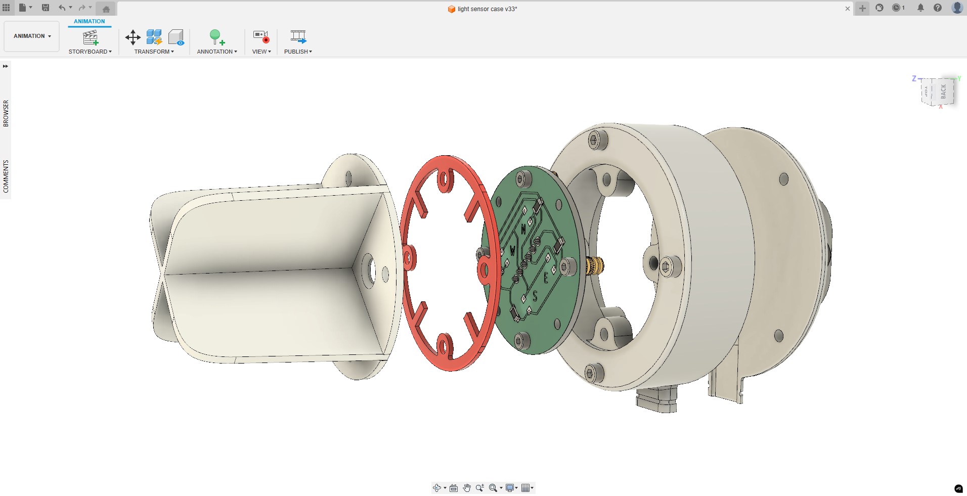
LIGHT SENSOR ARRAY
I also designed and fabricated the phototransistor sensor array PCB and its 3D-printed enclosure, which connects back to the microcontroller board through a header and provides the four directional light signals used for automatic tracking.


12V POWER DISTRIBUTION BOARD
High-current loads (stepper motor, linear actuator and DC–DC converter) are handled by a separate 12 V power distribution PCB.
This board includes a pair of screw terminals labeled 12 V IN that bring in the 12 V battery output. It also has a switch connection that goes to the external rocker on/off switch on the enclosure. This allows all loads to be disconnected while keeping the battery and charge controller connected.
From the switched 12 V PWR rail, the board branches out to several groups of terminals for:
- the stepper motor driver
- the linear actuator
- the 12 V to 5 V buck converter
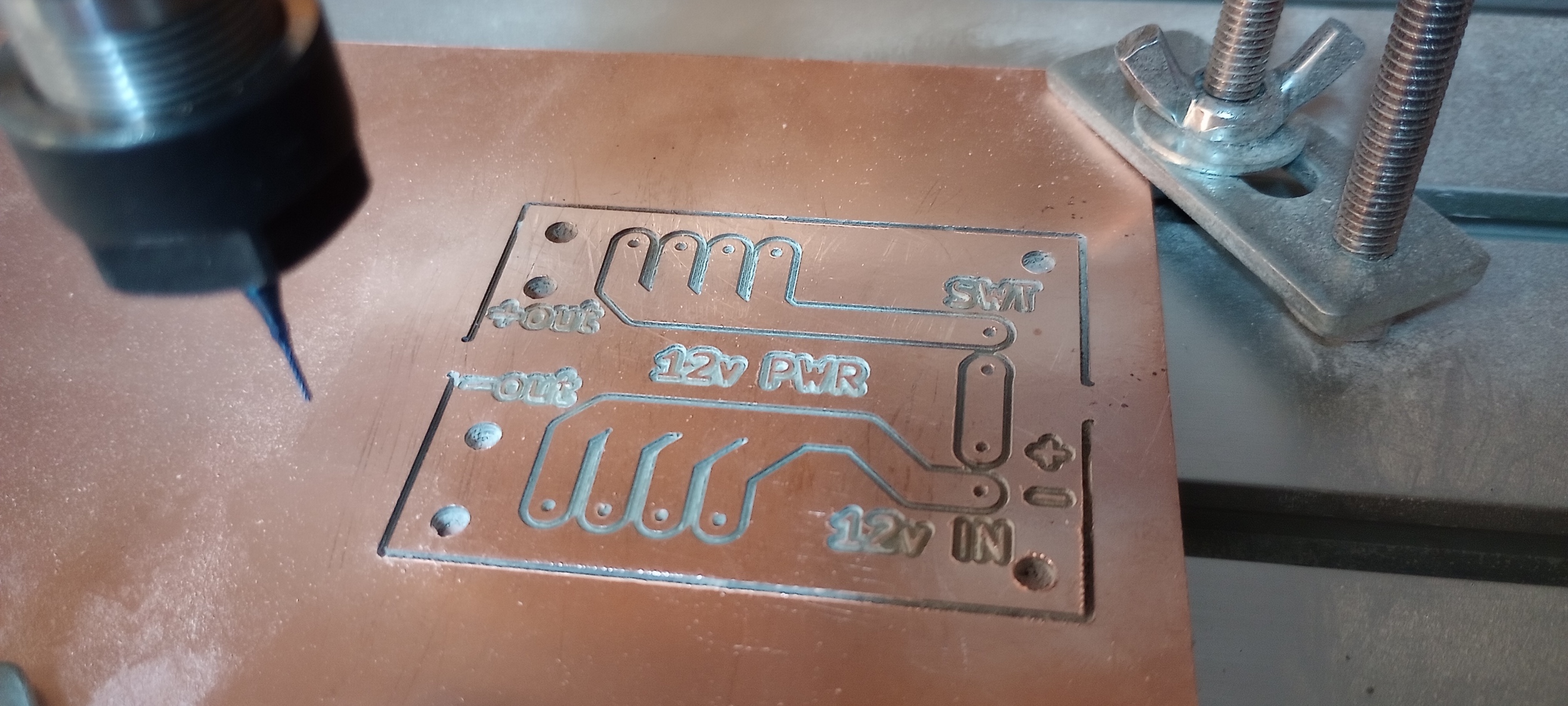
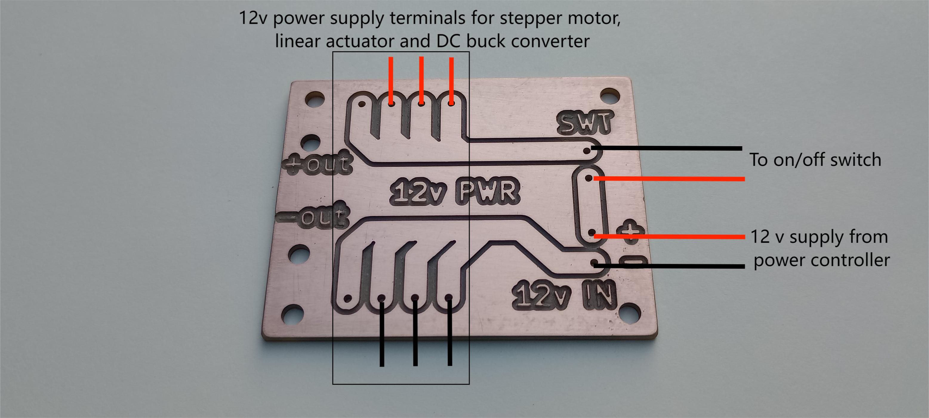
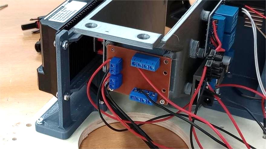
The copper traces on this board are wide and short to handle the current of the actuators and to keep the wiring inside the enclosure tidy. Using this simple distribution board avoids having a cluster of separate wires twisted together on a single screw terminal.
TopFIRMWARE
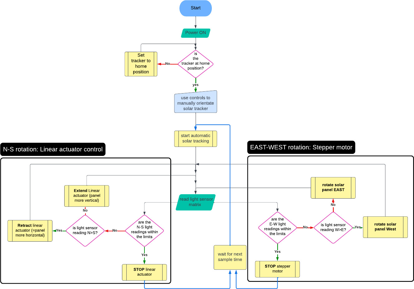
The firmware for the dual-axis solar tracker runs on the Seeed Studio XIAO ESP32-C6 and is organized around three main functions: automatic sun tracking, night mode, and manual control via BLE. The behaviour is described by the flowcharts below.
Automatic tracking loop
When the user starts automatic tracking, the main loop runs periodically (every tracking interval):
- Read light sensor matrix: the four phototransistors (N, S, E, W) are sampled.
- The firmware calculates the N–S and E–W differences and compares them with a tolerance band.
- N–S axis (linear actuator): If the north sensor reads significantly higher than the south sensor, the firmware retracts the actuator to make the panel more horizontal.
- If the south sensor is higher, it extends the actuator to make the panel more vertical.
- When the N–S readings fall within the allowed limits, the actuator is stopped.
- E–W axis (stepper motor): If the west sensor reads higher than the east sensor, the stepper rotates the panel towards the West.
- If the east sensor is higher, it rotates towards the East.
- the motor is stopped when the E–W readings are within limits or a safety limit is reached.
After both axes have been updated, the firmware waits until the next sample time and repeats the process.
This control strategy moves the panel in small increments until the four sensors are balanced, keeping the panel roughly perpendicular to the sun.
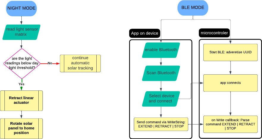
Night mode
In parallel, the firmware monitors the overall light level: The light sensor matrix is read and compared to a daylight threshold. If the readings fall below this threshold (it is dark), the firmware switches to Night Mode: the linear actuator is fully retracted, keeping the panels horizontally.
If the light level is still above the threshold, the tracker continues automatic tracking.
Solar Tracker code: BLE, AZIMUTH, ELEVATION
// =====  Solar Tracker: BLE + 30 s interval (20 s burst), AZIMUTH then ELEVATION =====

#include
#include
#include
#include
#include

// ---------------- Pins ----------------
#define RELAY_EXTEND   D5      // linear actuator relays (ACTIVE LOW)
#define RELAY_RETRACT  D4

#define STEP_PIN       D6      // stepper STEP
#define DIR_PIN        D7      // stepper DIR

// Light sensors (XIAO back pads use GPIO numbers for 4/5/6)
#define SENSOR_N       5
#define SENSOR_S       D0
#define SENSOR_E       4
#define SENSOR_W       6

// ---------------- Direction toggles (no rewiring) ----------------
#define EAST_IS_CW              1   // 1: CW aims EAST, 0: CW aims WEST
#define MORE_VERTICAL_IS_EXTEND 0   // 1: EXTEND raises elevation

// ---------------- Tuning ----------------
static const int      DEADBAND          = 80;             // both axes
static const uint32_t CONTROL_PERIOD_MS = 300;             // auto step cadence
static const uint32_t TRACK_INTERVAL_MS = 10UL * 60UL * 1000UL;   // 10 min between bursts
static const uint32_t TRACK_BURST_MS    = 20000UL;         // 20 seconds per burst
static const uint32_t DEFAULT_RUN_MS    = 10000UL;         // actuator safety cap
static const uint32_t NIGHT_RETRACT_MS  = 8000UL;          // retract 8 s in night mode
static const uint32_t HOME_RETRACT_MS   = 8000UL;          // retract 8 s on HOME   (NEW)
static const int      NIGHT_THR         = 400;             // brightest < NIGHT_THR => night

// ---------------- Stepper ----------------
AccelStepper stepper(AccelStepper::DRIVER, STEP_PIN, DIR_PIN);
const float MAX_SPEED = 300.0f;     // steps/s
const float JOG_SPEED = 100.0f;     // steps/s
float currentSpeed = 0.0f;
static inline void setSpeedClamped(float s){
  if (s >  MAX_SPEED) s =  MAX_SPEED;
  if (s < -MAX_SPEED) s = -MAX_SPEED;
  currentSpeed = s;
  stepper.setSpeed(currentSpeed);
}

// ---------------- State ----------------
enum Motion { STOPPED, EXTENDING, RETRACTING };
volatile Motion motion = STOPPED;

bool trackingEnabled = false;
bool inBurst         = false;

BLECharacteristic* cmdChar = nullptr;
uint32_t stopAtMs    = 0;     // actuator safety timer
uint32_t nextBurstAt = 0;
uint32_t burstEndsAt = 0;

// ---------------- Helpers ----------------
static inline void stopActuator(){ digitalWrite(RELAY_EXTEND, HIGH); digitalWrite(RELAY_RETRACT, HIGH); motion = STOPPED; }
static inline void extendActuator(){ digitalWrite(RELAY_EXTEND, LOW);  digitalWrite(RELAY_RETRACT, HIGH); motion = EXTENDING; }
static inline void retractActuator(){ digitalWrite(RELAY_EXTEND, HIGH); digitalWrite(RELAY_RETRACT, LOW);  motion = RETRACTING; }
static inline int bright(uint8_t pin){ return 4095 - analogRead(pin); } // higher = brighter

// ---- Auto step (runs at most every CONTROL_PERIOD_MS). AZIMUTH first, then ELEVATION.
static inline void autoStep(){
  static uint32_t last = 0;
  uint32_t now = millis();
  if (now - last < CONTROL_PERIOD_MS) return;
  last = now;

  int n = bright(SENSOR_N);
  int s = bright(SENSOR_S);
  int e = bright(SENSOR_E);
  int w = bright(SENSOR_W);

  // ---- Serial plot: N,S,W,E (CSV) ----
  Serial.print(n); Serial.print(',');
  Serial.print(s); Serial.print(',');
  Serial.print(w); Serial.print(',');
  Serial.println(e);

  // night mode: retract 8 s, no rotation
  int brightest = max(max(n, s), max(e, w));
  if (brightest < NIGHT_THR){
    if (motion != RETRACTING){ retractActuator(); stopAtMs = now + NIGHT_RETRACT_MS; } // 8 s
    setSpeedClamped(0);   // no rotation
    return;               // stay in night behaviour during burst; scheduler will end burst on time
  }

  // 1) AZIMUTH (E/W)
  int diffEW = e - w;                      // >0 => EAST brighter
  if (abs(diffEW) > DEADBAND){
    float spd = (diffEW > 0) ? JOG_SPEED : -JOG_SPEED;  // toward brighter
  #if EAST_IS_CW
    setSpeedClamped(spd);
  #else
    setSpeedClamped(-spd);
  #endif
    if (motion != STOPPED){ stopActuator(); stopAtMs = 0; }
    return;                                 // finish azimuth first
  } else {
    if (currentSpeed != 0.0f) setSpeedClamped(0);
  }

  // 2) ELEVATION (N/S)
  int diffNS = s - n;                      // >0 => SOUTH brighter
  if (abs(diffNS) > DEADBAND){
    bool moreVertical = (diffNS > 0);
  #if MORE_VERTICAL_IS_EXTEND
    Motion desired = moreVertical ? EXTENDING : RETRACTING;
  #else
    Motion desired = moreVertical ? RETRACTING : EXTENDING;
  #endif
    if (desired == EXTENDING && motion != EXTENDING){
      extendActuator(); stopAtMs = now + DEFAULT_RUN_MS;
    } else if (desired == RETRACTING && motion != RETRACTING){
      retractActuator(); stopAtMs = now + DEFAULT_RUN_MS;
    }
  } else {
    if (motion != STOPPED){ stopActuator(); stopAtMs = 0; }
  }
}

// ---------------- BLE  ----------------
class WriteCB : public BLECharacteristicCallbacks {
  void onWrite(BLECharacteristic* ch) override {
    String s = String(ch->getValue().c_str());
    s.trim(); s.toUpperCase();            // "home" -> "HOME"
    if (!s.length()) return;

    // Manual tilt
    if (s=="EXTEND" || s=="E"  || s=="1"){  extendActuator();  stopAtMs = millis() + DEFAULT_RUN_MS; return; }
    if (s=="RETRACT"|| s=="R"  || s=="-1"){ retractActuator(); stopAtMs = millis() + DEFAULT_RUN_MS; return; }
    if (s=="STOP"   || s=="S"  || s=="0"){  stopActuator();     stopAtMs = 0;                         return; }

    // Manual azimuth
    if (s=="CW"){     setSpeedClamped((currentSpeed > 0) ? currentSpeed : JOG_SPEED);  return; }
    if (s=="CCW"){    setSpeedClamped((currentSpeed < 0) ? currentSpeed : -JOG_SPEED); return; }
    if (s=="STOP_R"){ setSpeedClamped(0);                                              return; }

    // --- HOME (retract 8 s, stop rotation, end burst) ---
    if (s=="HOME"){
      setSpeedClamped(0);                 // no rotation while homing
      retractActuator();
      stopAtMs  = millis() + HOME_RETRACT_MS;   // 8 s retract
      inBurst   = false;                        // end any active burst
      nextBurstAt = millis() + TRACK_INTERVAL_MS; // schedule next burst
      return;
    }

    // Scheduler
    if (s=="START_TRACK"){ trackingEnabled = true;  inBurst = false; nextBurstAt = millis(); return; }
    if (s=="STOP_TRACK"){  trackingEnabled = false; inBurst = false; setSpeedClamped(0); stopActuator(); return; }
  }
};

// ---------------- Setup / Loop ----------------
void setup(){
  Serial.begin(115200);

  pinMode(RELAY_EXTEND,  OUTPUT);
  pinMode(RELAY_RETRACT, OUTPUT);
  stopActuator();

  pinMode(STEP_PIN, OUTPUT);
  pinMode(DIR_PIN,  OUTPUT);
  stepper.setMaxSpeed(MAX_SPEED);
  setSpeedClamped(0);

  BLEDevice::init("XIAO_C6_Solar_Tracker");
  BLEServer*  server  = BLEDevice::createServer();
  BLEService* service = server->createService("4fafc201-1fb5-459e-8fcc-c5c9c331914b");
  BLECharacteristic* ch = service->createCharacteristic(
      "beb5483e-36e1-4688-b7f5-ea07361b26a8",
      BLECharacteristic::PROPERTY_READ | BLECharacteristic::PROPERTY_WRITE);
  ch->setCallbacks(new WriteCB());
  ch->setValue("READY");
  service->start();
  BLEAdvertising* adv = BLEDevice::getAdvertising();
  adv->addServiceUUID("4fafc201-1fb5-459e-8fcc-c5c9c331914b");
  adv->start();
}

void loop(){
  // Keep stepper running at last speed
  stepper.runSpeed();

  // Actuator safety stop
  uint32_t now = millis();
  if (stopAtMs && now >= stopAtMs){ stopActuator(); stopAtMs = 0; }

  // 30-second scheduler with 20-second burst
  if (trackingEnabled){
    if (!inBurst){
      if (now >= nextBurstAt){
        inBurst = true;
        burstEndsAt = now + TRACK_BURST_MS;
      }
    } else {
      autoStep();                               // azimuth first, then elevation
      if (now >= burstEndsAt){
        setSpeedClamped(0);
        stopActuator();
        inBurst = false;
        nextBurstAt = millis() + TRACK_INTERVAL_MS;  // 30 s
      }
    }
  }

  delay(1);
}
APP FOR BLE CONTROL
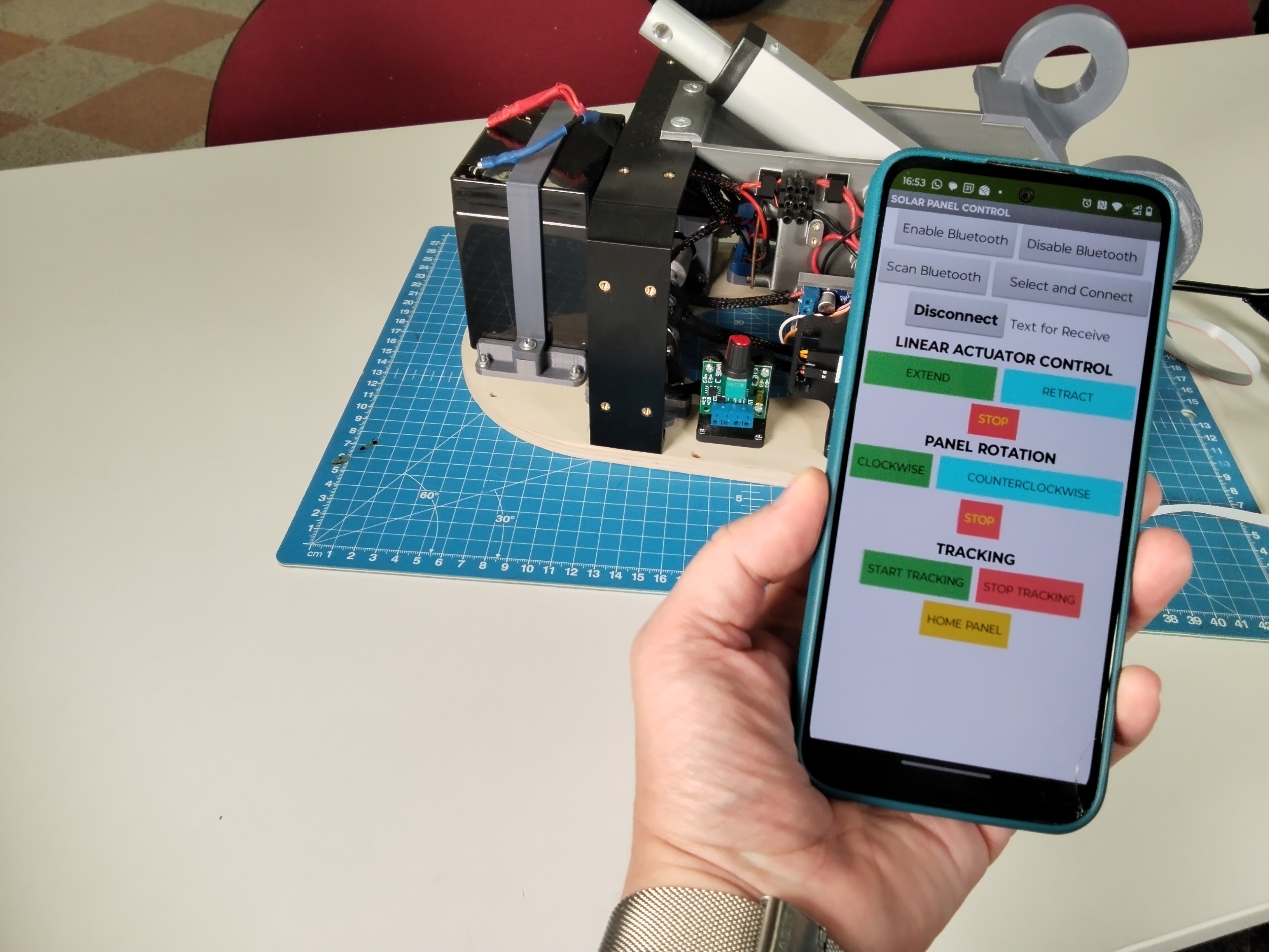
One of the features I wanted for the project was a way to control the solar tracker via wireless communication. Since I was using a XIAO ESP32-C6, I decided to use Bluetooth Low Energy (BLE) to control the tracker from a mobile phone.
BLE provides a low-power way to communicate with the tracker using a standard smartphone, without needing extra hardware like a dedicated remote or Wi-Fi router. BLE has a short short-range (a few meters) but since the user only needs to be near the device during setup, testing, or manual adjustment it is appropriate technology for this case.
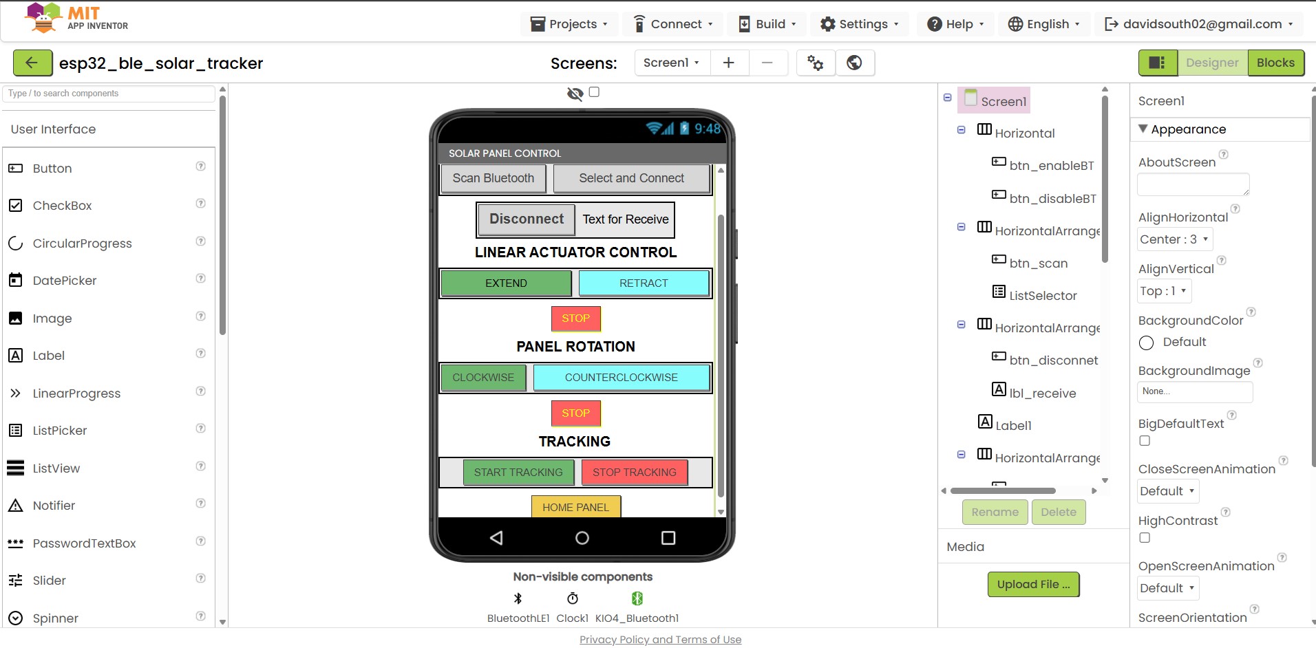
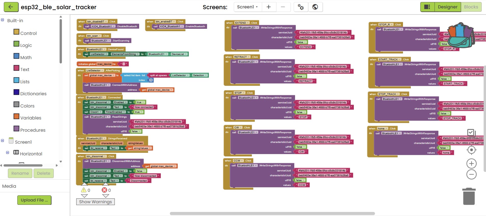
During Week 15 (Interface and Application Programming) I experimented with MIT App Inventor, a free, block-based tool for building mobile apps. I already had a basic BLE example, so I used it as a starting point and extended it to create a custom app for my solar tracker. The app can scan for nearby Bluetooth devices, list them, and let the user select and connect to the solar tracker.
Once connected, the interface provides buttons to control tilt and rotation manually. This allows the user to perform the initial orientation of the panels or to fix the solar panel in a desired position. In addition, the app has a button to start automatic sun tracking, where the panel orientation is updated according to the sensor readings. There are also buttons to stop the automatic tracking and to send the tracker back to its “home” position, with the panel horizontal.
Top
BILL OF MATERIALS
| Ref. | Description | Size | Qty | Unit cost (€) | Total (€) |
|---|---|---|---|---|---|
| Solar panel assembly | |||||
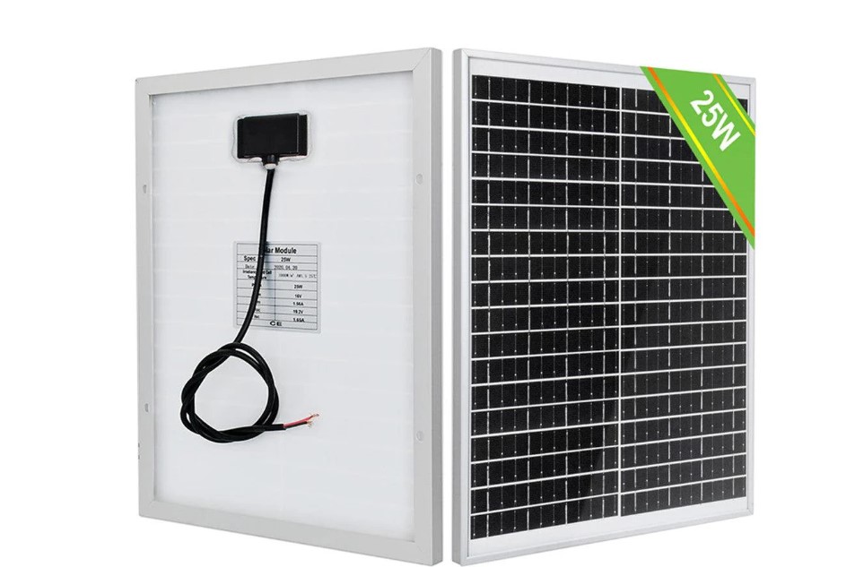
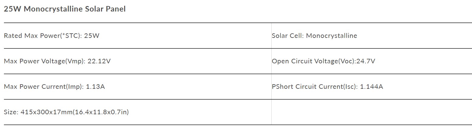
| 1 | 25W 12V Monocrystalline Solar Panel | 420x320x17 mm | 2 | 29.00 | 58.00 |
| 2 | Extruded aluminium profile T-slot 2020 | 20x20x600 mm | 3 | 4.75 | 14.25 |
| 3 | T-slot 90º angle connectors (for 2020 profiles) | 25x25x6 mm | 20 | 0.23 | 4.50 |
| 4 | Ball bearing 6808-2RS (52mm outer diameter) | 40x25x7 mm | 2 | 6.00 | 12.00 |
| 5 | Ball bearing 6262ZZ (19mm outer diameter) | 19x6x6 mm | 2 | 0.65 | 1.30 |
| 6 | Self-locking MC-4 solar panel wire connector | 2 | 1.50 | 3.00 | |
| Electronics | |||||
| 7 | PWM DC motor speed controller (1.8–15 V) | 1 | 2.50 | 2.50 | |
| 8 | Buck converter module DC 12V to 5V | 63x27 mm | 1 | 7.00 | 7.00 |
| 9 | Stepper driver board | 36x36 mm | 1 | 4.99 | 4.99 |
| 10 | DRV8825 stepper motor driver | 1 | 4.00 | 4.00 | |
| 11 | Battery LiFePO4 12V 6Ah | 90x70x101 mm | 1 | 26.99 | 26.99 |
| 12 | Seeed Studio XIAO ESP32-C6 | 21x17.55 mm | 1 | 5.74 | 5.74 |
| 13 | Solar charger controller 12V/24V 30A | 133x70x26 mm | 1 | 15.19 | 15.19 |
| 14 | Ribbon wire and connectors | 1 | 3.00 | 3.00 | |
| 15 | Copper PCB board FR1 | 100x70 mm | 4 | 0.60 | 2.40 |
| 16 | SMD components (resistors, phototransistors, push button, LED) | 1 | 5.00 | 5.00 | |
| Mechanical | |||||
| 17 | Axle 8 mm diameter | diam 8 mm | 1 | 6.00 | 6.00 |
| 18 | Axle bearing block for 8 mm axle | 55x29 mm | 1 | 3.40 | 3.40 |
| 19 | NEMA 17 motor to M8 axle coupling | 25x20 mm | 1 | 4.49 | 4.49 |
| 20 | M8 flanged axle connector | M8 | 1 | 3.00 | 3.00 |
| 21 | Stepper motor NEMA 17 (17HE15-1504S) | 42x42x38 mm | 1 | 11.90 | 11.90 |
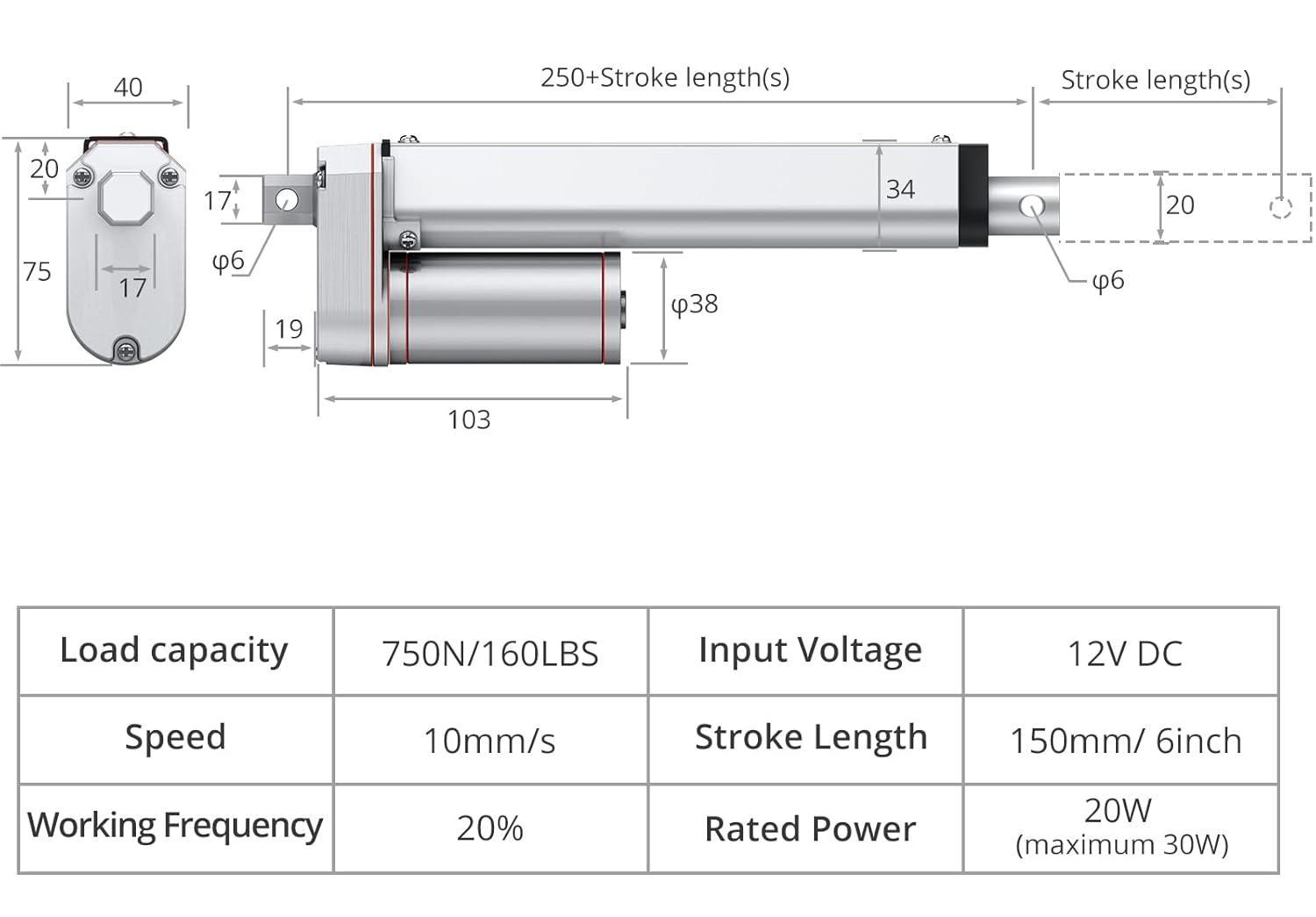
| 22 | Justech DC 12V linear actuator 750N 100 mm | 105x75x40 mm | 1 | 33.99 | 33.99 |
| 23 | Filament PETG 1.75 mm | 1 kg | 1 | 19.99 | 19.99 |
| 24 | Fasteners (screws, bolts, nuts, heat-threaded inserts) | 1 | 6.00 | 6.00 | |
| Base and legs assembly | |||||
| 25 | Turntable 155 mm | 155x155x8 mm | 1 | 11.99 | 11.99 |
| 26 | 10 mm plywood | 1200x600x10 mm | 1 | 18.00 | 18.00 |
| Total= | 288.62€ | ||||
25W 12V Monocrystalline Solar Panel
12v LINEAR ACTUATOR 100mm Stroke
Nema 17 Bipolar 42Ncm(59.49oz.in) 1.5A 42x42x38mm 4 Wires
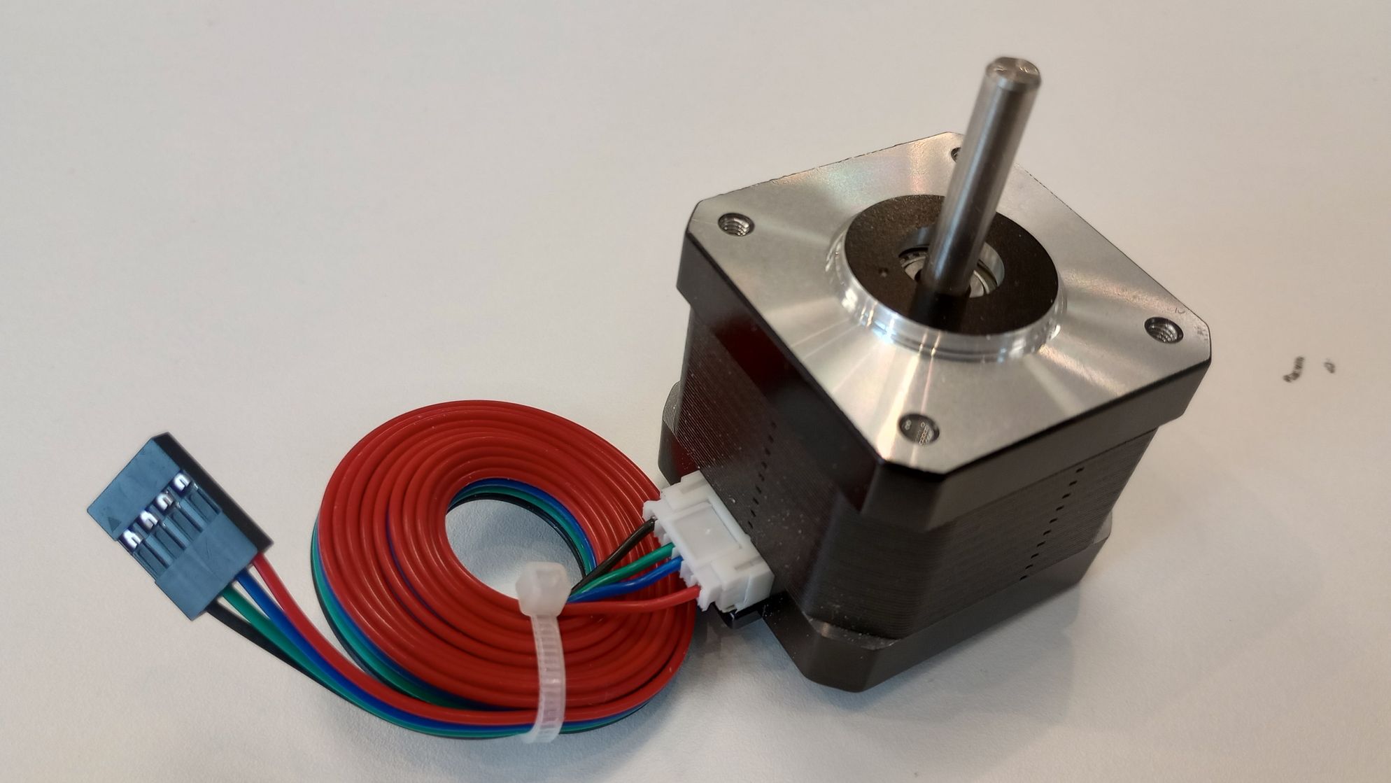
Electrical Specification
- Manufacturer Part Number: 17HE15-1504S
- Motor Type: Bipolar Stepper
- Step Angle: 1.8deg
- Holding Torque: 42Ncm(59.49oz.in)
- Rated Current/phase: 1.50A
- Phase Resistance: 2.3ohms
- Inductance: 4.0mH±20%(1KHz)
Top
USEFUL LINKS AND RESOURCES
- How Do You Control a Linear Actuator with an Arduino? Posted by Firgelli Automations Team on May 29, 2020
- Optimization Controller for Mechatronic Sun Tracking System to Improve Performance Engin, Mustafa & Engin, Dilşad. (2015). Optimization Controller for Mechatronic Sun Tracking System to Improve Performance. Advances in Mechanical Engineering. 2013.
- Low cost solar panel solution (MPPT + sun tracker) by JP Gleyzes
PROJECT FILES
CAD FILES FOR 3D PRINTING
stl files for light sensor case: light_sensor_case.zip
stl files for gear train: gear_parts.zip
stl files for electronics mounts: mounts_electronics.zip
stl files for linear actuator and panels: linear_actuator_and_panel.zip
stl files for enclosure: enclosure_parts.zip
stl files for legs: base_parts.zip
FILES FOR CNC CUTTING
2D CAD file for base andlegs: base_legs_CNC.dxf
ELECTRONICS FILES
Microcontroller PCB
KiCad9.0 files for microcontroller embedded PCB: microcontroller_PCB_KICAD9_files.zip
png files for microcontroller PCB fabrication: microcontroller_PCB_png_files.zip
Light sensor PCB
KiCad9.0 files for light sensor PCB: light_sense_matrix_PCB_KICAD9_files.zip
png files for light sensor PCB fabrication: ligth_sense_matrix_PCB_png_files.zip
12v DC Power distribution PCB
KiCad9.0 files for 12v DC Power distribution PCB: 12v_power_PCB_KICAD9_files.zip
png files for 12v DC Power distribution PCB fabrication: 12v_power_PCB_png_files.zip
BLE APP FILES
Android app installation file: esp32_ble_solar_tracker.zip
MIT App Inventor project: esp32_ble_solar_tracker.aia
FIRMWARE FILES
Arduino IDE code: solar_tracker_firmware.ino
Top