9. Output devices
This week we got to know how to use output devices. During the group work we measured the current (I) consumption of a neopixel led strip using both a multimeter and a usb current measurement devices. Since the voltage U was 5V, the power could be calculated as P=UI.
Testing output devices
Neopixel led strip
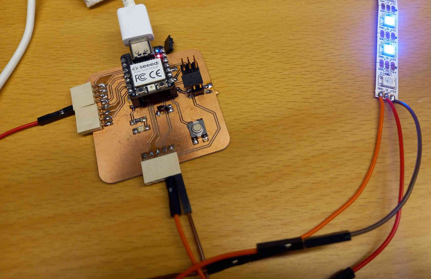
I used the Neopixel led strip to test my board operation. I first used the same code as we did in the group work, which was based on Akseli Uunilas Neopixel code.
I modified the code to output different colors at faster pace, and debugged the switch case block (I noticed that it was needed to add break at the end of each case).
The modified code is:
#include <Adafruit_NeoPixel.h>


#define NEOPIXELPIN D0 // Datapin for the the built-in NeoPixel

#define NUMPIXELS 4 //Amount of NeoPixels

Adafruit_NeoPixel pixels(NUMPIXELS, NEOPIXELPIN, NEO_RGB + NEO_KHZ800);

#define DELAYVAL 500 // Time (in milliseconds) to pause between loop

void setup() {
  pixels.begin();
  Serial.begin(9600);
}

void loop() {

int bl;
int R=0;
int G=0;
int B=255;
for(bl=0;bl<=2;bl++){
  //Serial.println(bl);
  switch(bl){
    case 0:
        R=255;
        G=0;
        B=0;
        pixels.clear();
        pixels.setPixelColor(2, pixels.Color(R, G, B));
        pixels.show(); // Send the updated pixel colors to the hardware.
        //delay(DELAYVAL); // wait between

        //pixels.clear();
        pixels.setPixelColor(1, pixels.Color(R, G, B));
        pixels.show();
        //delay(DELAYVAL); // wait between

        //pixels.clear();
        pixels.setPixelColor(0, pixels.Color(R, G, B));
        pixels.show();
        Serial.println(bl);
        delay(DELAYVAL);
        break; // I noticed that you need to end each case with break to exit

    case 1:
        R=0;
        G=255;
        B=0;
        pixels.clear();
        pixels.setPixelColor(2, pixels.Color(R, G, B));
        pixels.show(); // Send the updated pixel colors to the hardware.
        //delay(DELAYVAL); // wait between

        //pixels.clear();
        pixels.setPixelColor(1, pixels.Color(R, G, B));
        pixels.show();
        Serial.println(bl);
        delay(DELAYVAL); // wait between
        break;

    case 2:
        R=0;
        G=0;
        B=255;
        pixels.clear();
        pixels.setPixelColor(2, pixels.Color(R, G, B));
        pixels.show(); // Send the updated pixel colors to the hardware.
        Serial.println(bl);
        delay(DELAYVAL); // wait between
        break;

  }
  //bl++;
}

}
I tested the digital pins D0, D1, D2, D8, D9, D10 to check they were properly connected by using them separately as the digital pin in the neopixel led strip.
Photoresistor controlled led on my own circuit board
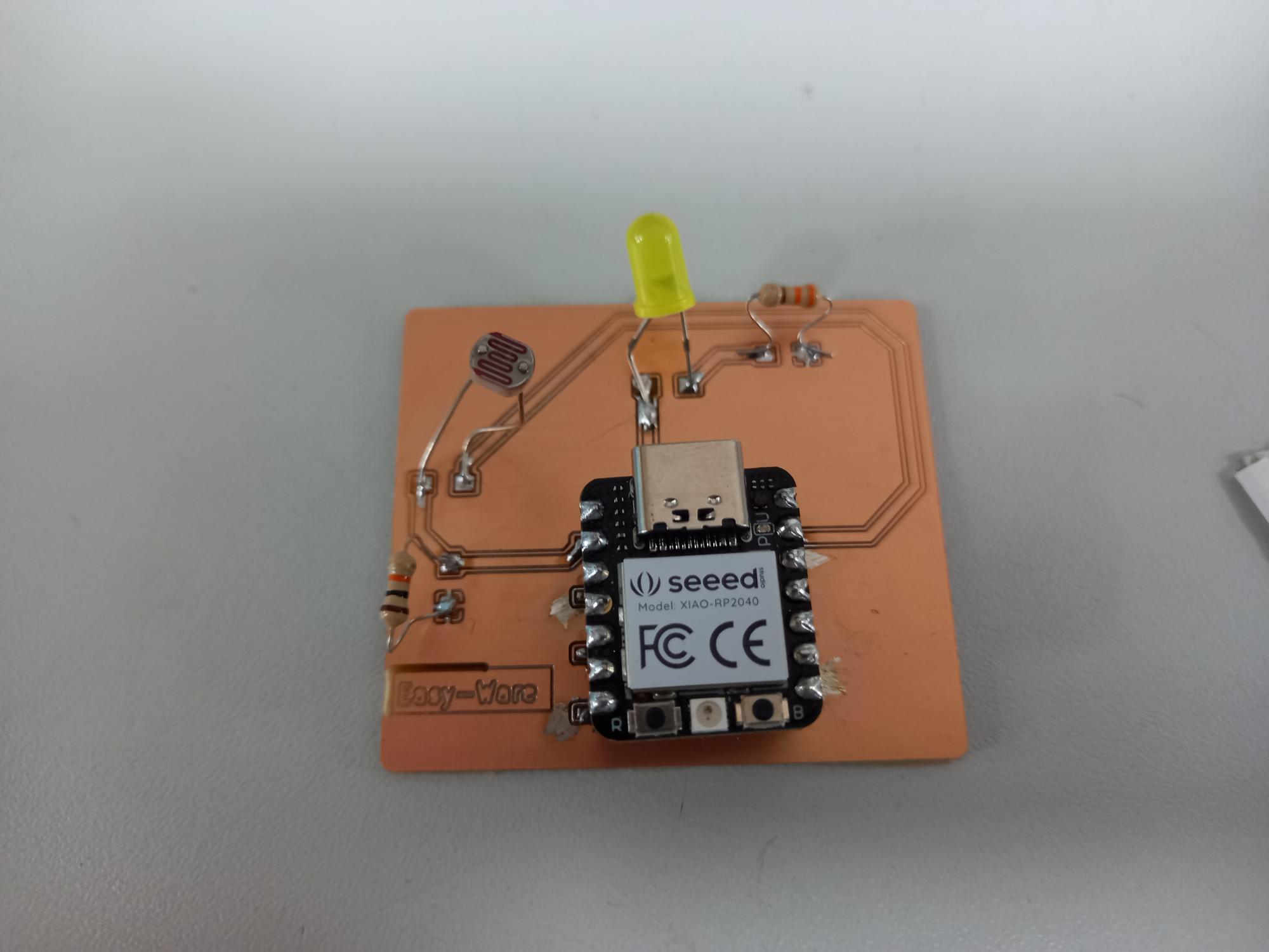
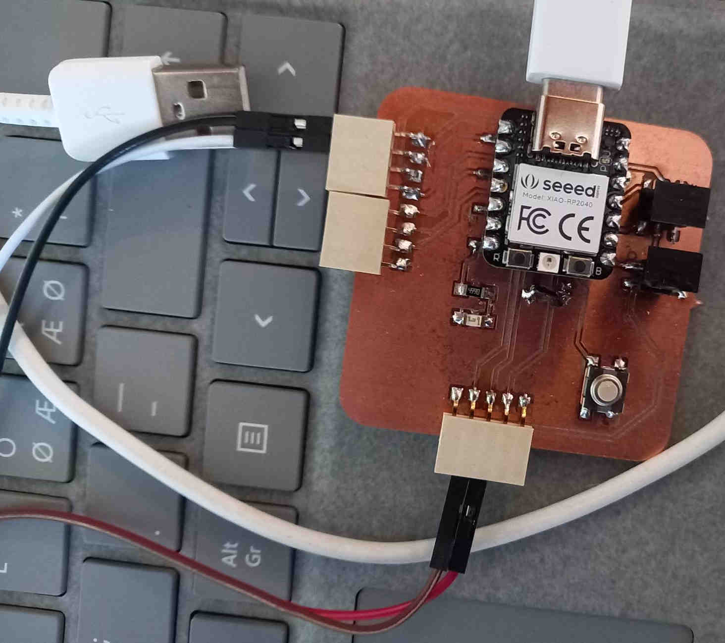
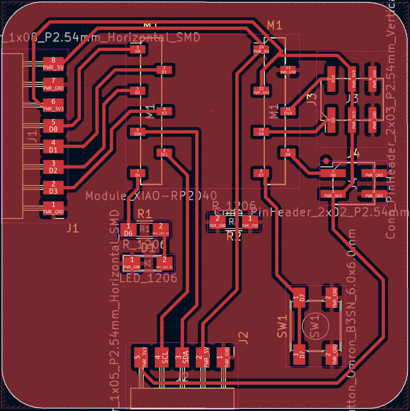
During embedded programming week I programmed a photoresistor controlled led, and during electronics design week I had designed a board for the components (see the links for the original design files). Now I milled a circuit board and soldered the components to it.
I had modified the blink code to read the light level and then turn the led on accordingly using pulse width modulation. The connections are described in detail in the previous weeks documentations, but the main idea is that the photoresistor changes the voltage on analog pin A0, and this is used to change the pulse width modulation on the led, which is connected to pin D1. The MCU that I used was RP2040.
int val =0;
int analogPin=A0;
int lightLevel=1;

// the setup function runs once when you press reset or power the board
void setup() {
  // initialize digital pin LED_BUILTIN as an output.
  pinMode(LED_BUILTIN, OUTPUT);
  pinMode(D1,OUTPUT);
  Serial.begin(9600);
}

// the loop function runs over and over again forever
void loop() {
  //digitalWrite(D1, HIGH);  // turn the LED on (HIGH is the voltage level)
  digitalWrite(D1, HIGH);
  delay(lightLevel-1);                      // wait for a second
  digitalWrite(D1, LOW);   // turn the LED off by making the voltage LOW
  delay(10-lightLevel);                      // wait for a second

  //delay(1000);
  val = analogRead(analogPin);  // read the input pin
  //Serial.println(val);         // print the value to the serial monitor
  lightLevel=map(val,500,1023,1,10);  // map lighLevel to values between 1 and 10
  lightLevel=constrain(lightLevel,1,10); // this clips the values in case they would go above or below 1 and 10
  //Serial.println(lightLevel); // print the lightLevel value to serial monitor

}
Oled screen
During the review lecture, I heard that fellow students from the other group from Oulu, Essi, Petra and Tapio, had tested the oled screen. I wanted also to get to know how to use the oled screen. I checked Essi‘s student page, and followed the procedure:
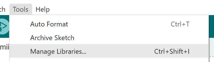
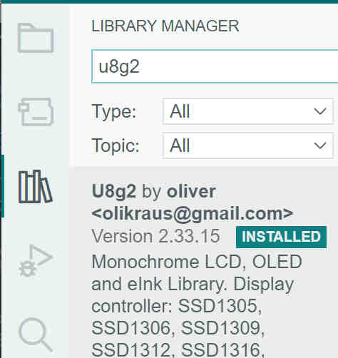
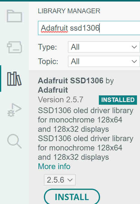
I checked Adriano’s page, which contains the links and instructions for using the oled screen. Using the library manager (tools->manage libraries) I installed the required libraries: u8g2 library and the Adafruit SSD1306 library.
I downloaded the test file by davekw7x from the original source, as suggested in the Adriano’s page.
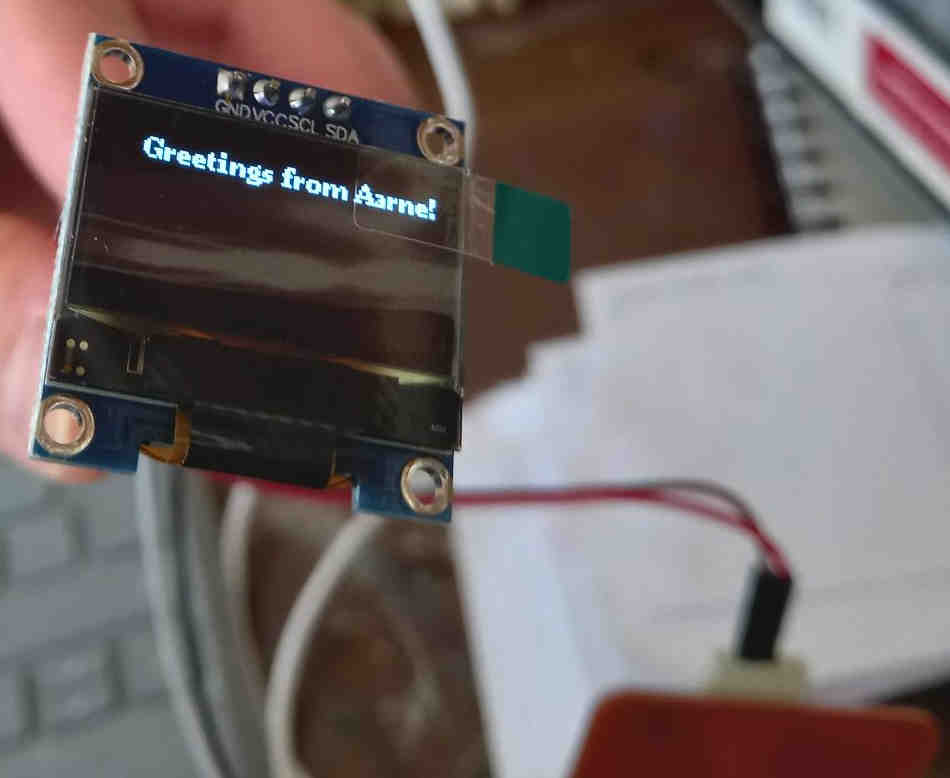
I connected the 5 V and ground pins to the GND and VCC pins of the oled screen and SCL and SDA pins of the board to the respective pins of the oled screen. For this point I received feedback that I should be more careful in connecting the device. The OLED screen in fact would operate with 3.3 V, and it needs pull-up resistors to be connected to the power source. Some devices could break if I use too high voltage and might not work properly if I omit the pull-up resistor. The OLED screen worked only because it had in-built regulator and pull up resistors, as described in the datasheet, so I was lucky this time. To avoid problems in the future I should always look the datasheet in advance.
After initial testing, I changed the output text to send greetings from myself to the world.
The modified code is here.
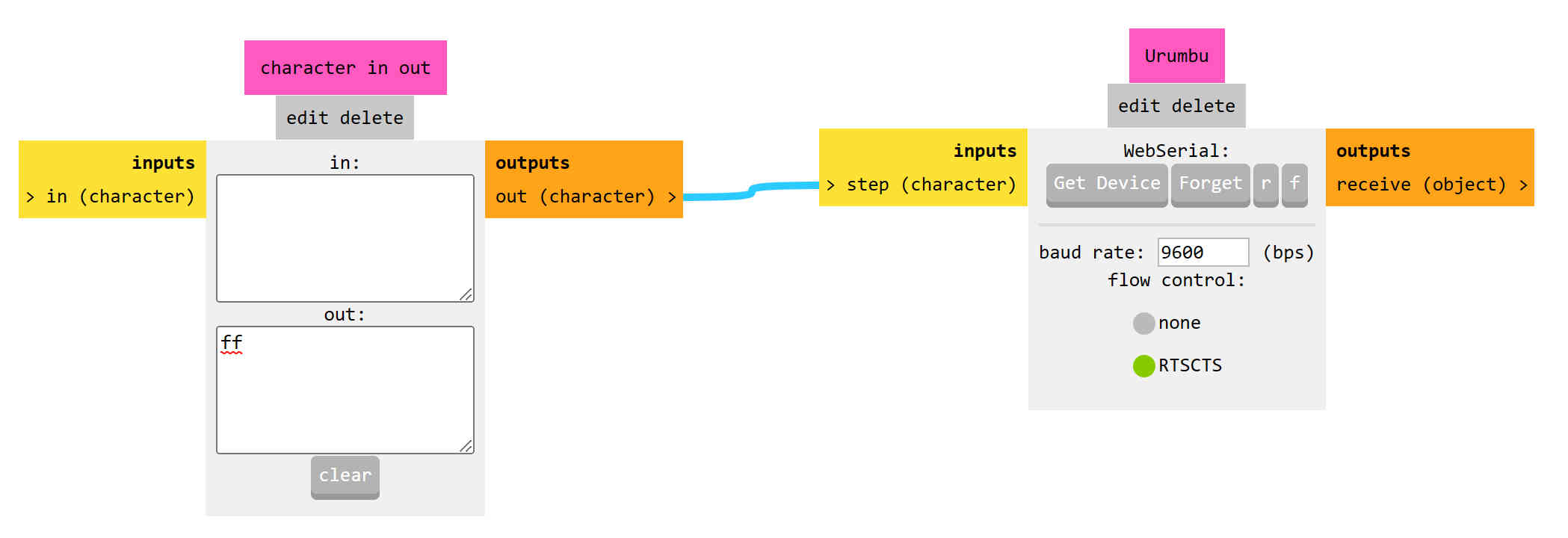
Urumbu and stepper motor
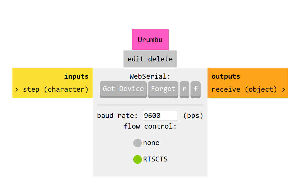
I tested using Urumbu and stepper motor. First, I connected the stepper motor driver to a usb hub provided by the fab lab. The motor driver was also provided for us.
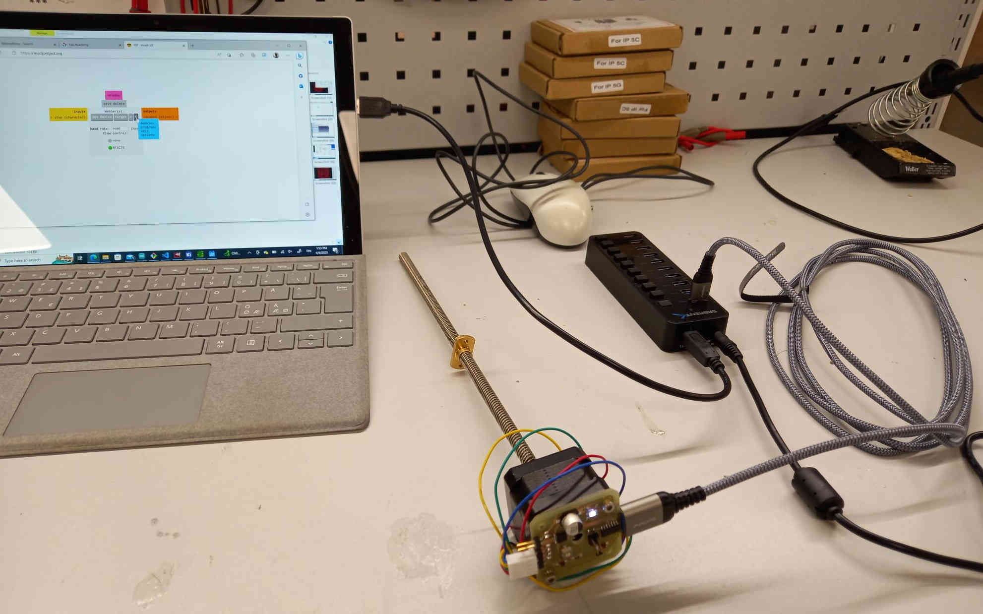
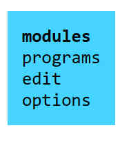
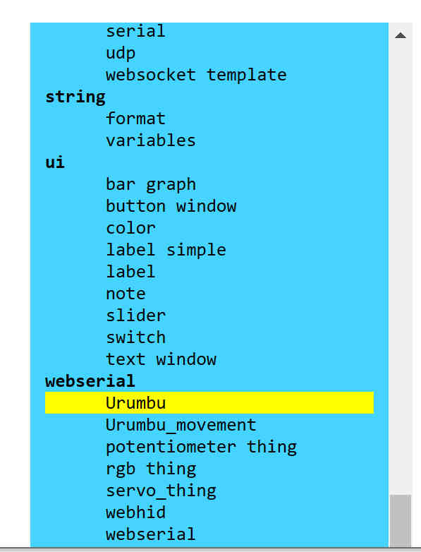
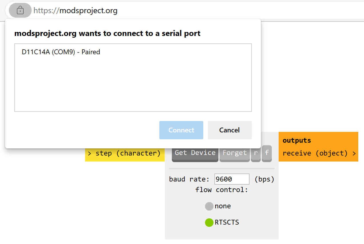
Then I used Mods to connect to the stepper motor.