4. Embedded programming
This week we started to get to know embedded programming. I have some experience in simple programming of Arduino boards, but already the first session gave me new information on how to install new boards to to the Arduino IDE, and where to look for the information on the pins.
Datasheet and board information
¶We were instructed to browse through the datasheets. From the datasheet (Raspberry Pi Trading limited, attributions no derivations licence 4.0, CC-BY-ND), it seems that the most important information for a complete beginner are the beginning chapters 1.1 and 1.2 on page 15. REP2040 has two processor cores and it runs at 133 MHz speed. The amount of memory is given (264 kB), which is important for the program size.
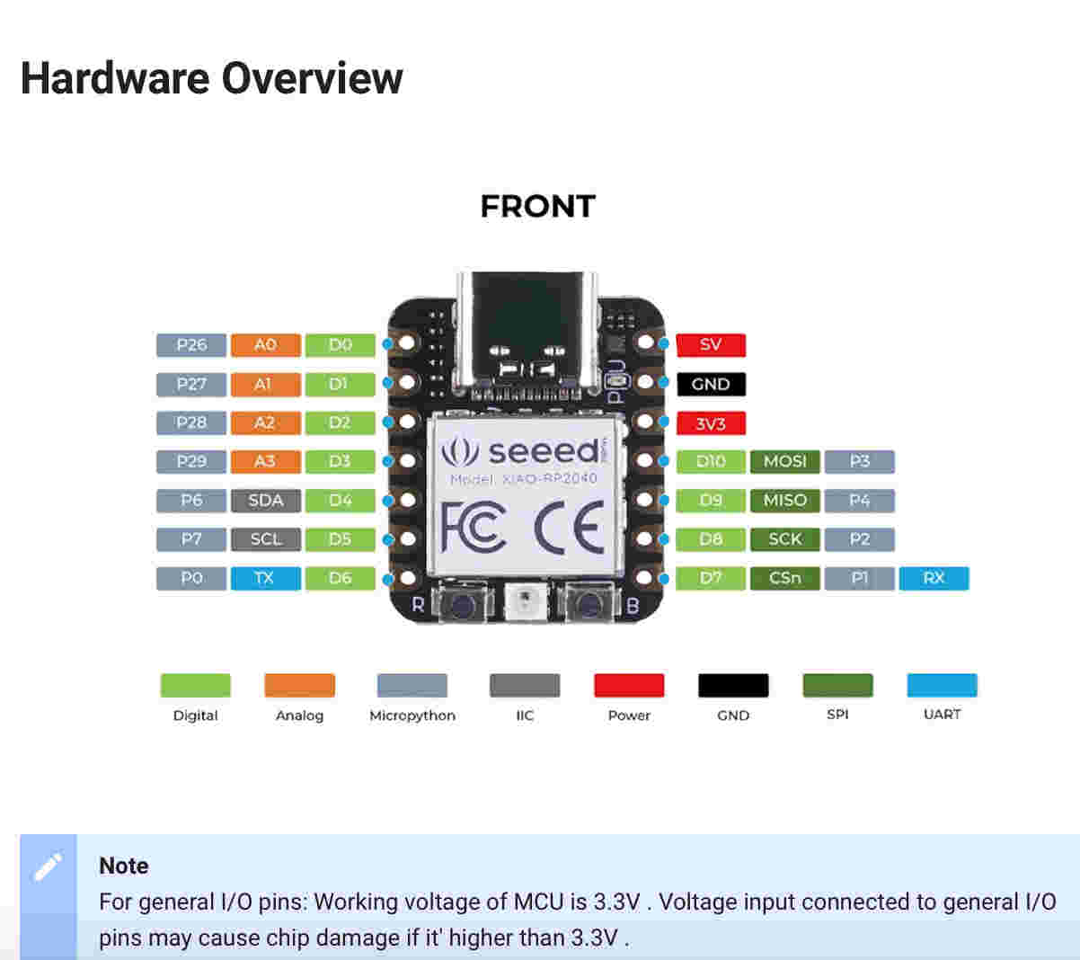
From the datasheet table of contents, I thought that the pin locations (Chapter 1.4.1) on the page 17 would be very important from the viewpoint of programming the board. I had not earlier looked at datasheets, and I was expecting to understand the pins that I saw in the board. However, I was bit surprised when I saw the pinout diagram. I could not relate it to what I was seeing on the board.
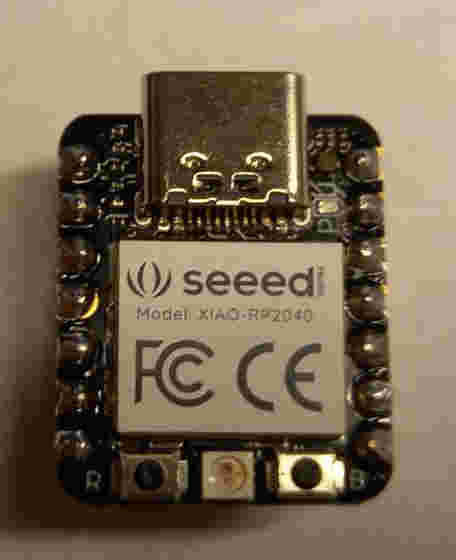
Then I realized, that it is actually the board information given by the board manufacturer (Seed Studio), which I should look to understand which pins I should actually connect.
So, if I understand it correctly, the datasheet is useful for the board manufacturer, who makes the connections. If I buy the board, it is the information provided by the board manufacturer (Seeed Studio in this case), that I should look for understanding what the pins are when I want to make the actual connections.
Installing new board to Arduino IDE and uploading a simple program to it
¶Prior to the group work, we installed Arduino IDE, added the boards to it, and tested blinking a led.
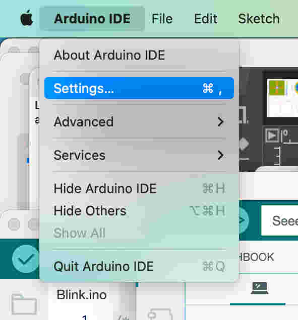
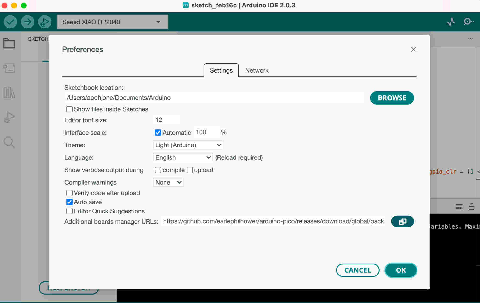
In Mac, the menu selection was a bit different from that on Windows machine, but I found it after searching for a while: Arduino IDE -> Settings.
In the window which opened, I pasted the board manager URLs.
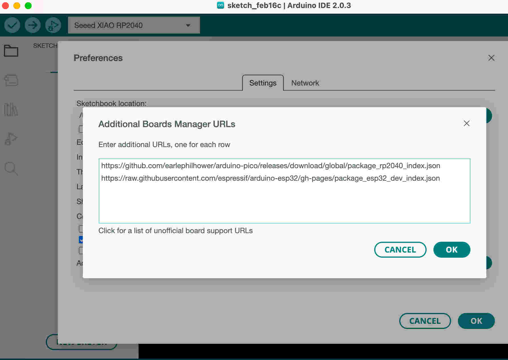
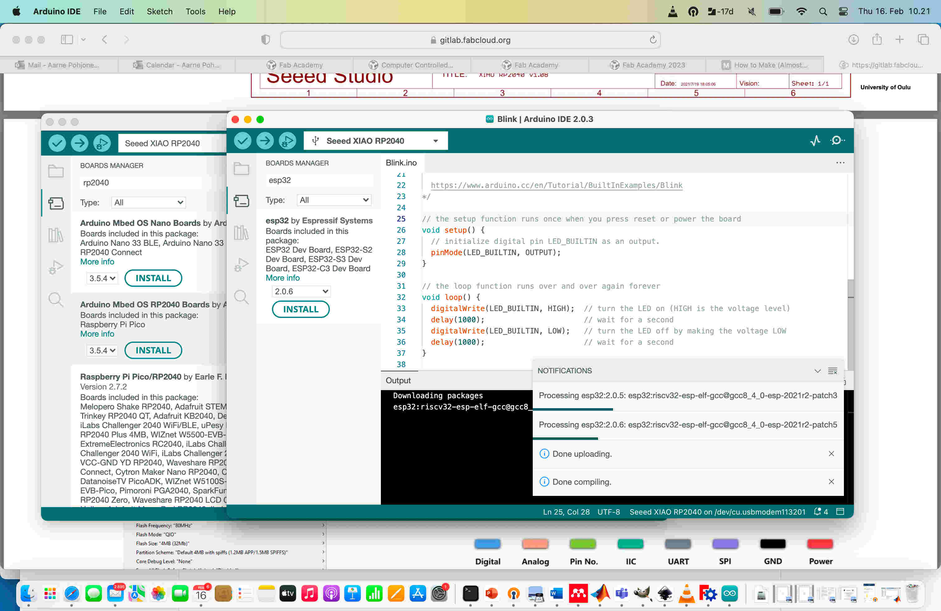
After pasting the URLs for RP2040 and ESP32 development boards, I pushed OK.
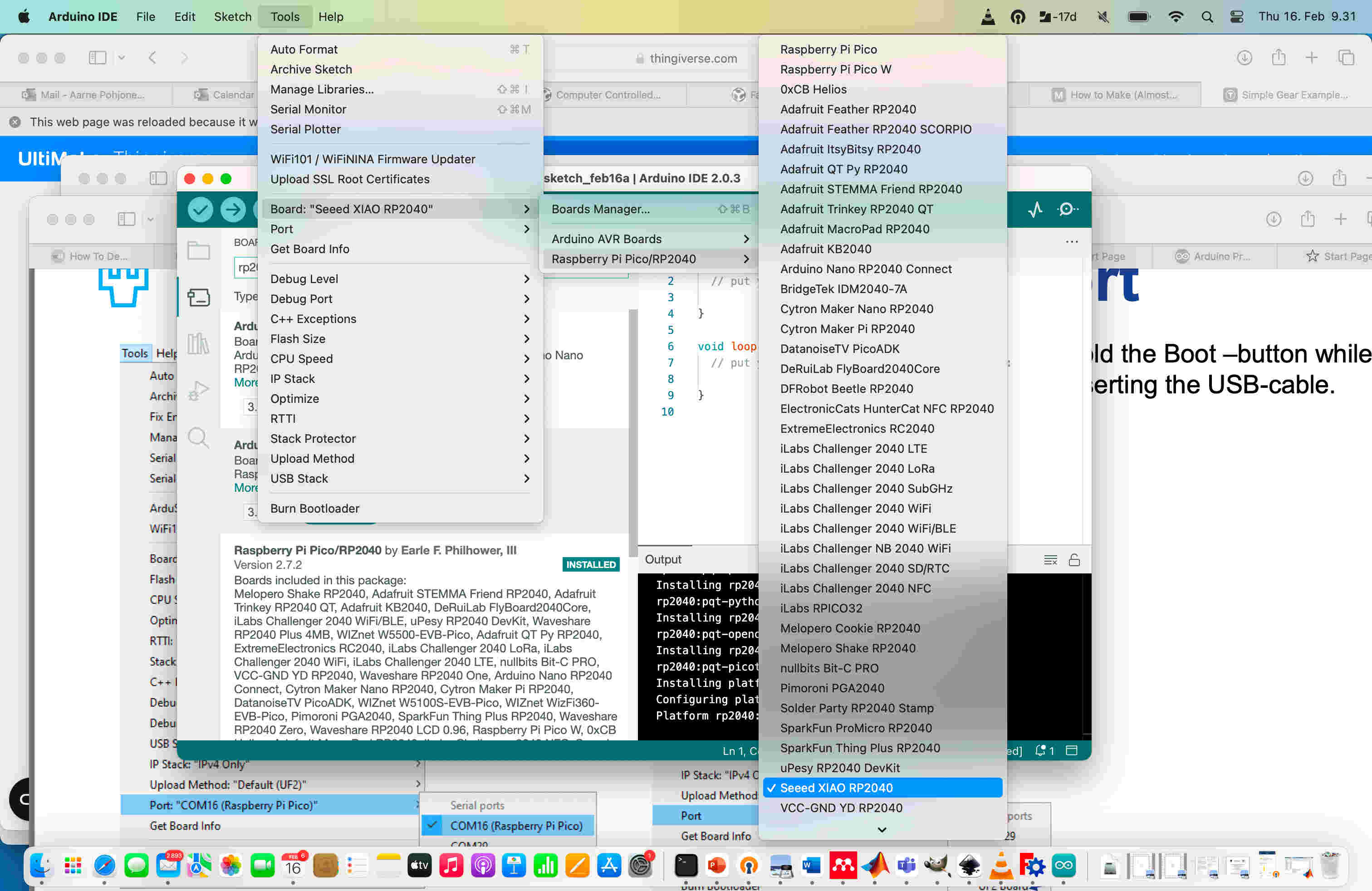
After installing the boards I then selected the correct board from the menu, and uploaded the example program for blinking a led to the board (File -> Examples -> 01.Basics -> Blink).
Speed test
¶We used the program (link) to test the speed of the processor.
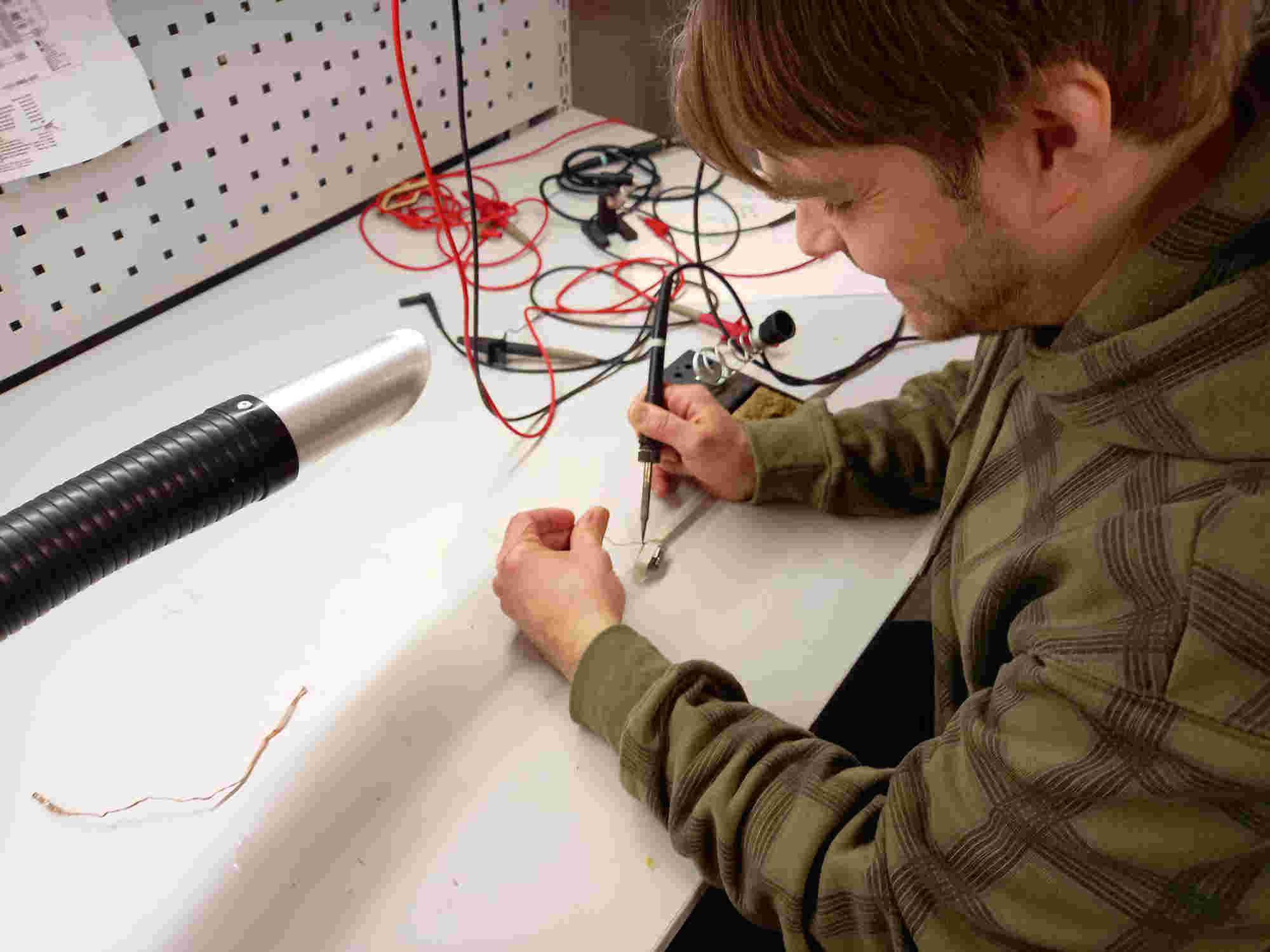
We soldered pins to the boards, so they could be easily attached to breadboard.
After this we proceeded to do the assigned group work. The idea of the test program is that one pin is used to send digital output and another pin is used for reading, and it is connected to the first pin. The output of the first pin is set to the opposite value of the reading of the second pin. This causes the output pin (first pin) to change the output value as soon as the value is received from the second pin. The program was uploaded to the microcontrollers.
During the group work, we connected the input and output pins using breadboard and jumper wires, as shown in the group work page. We measured the write/read speed of the different microcontrollers using an oscilloscope. There was not much problems, once we figured out the correct pins that we should measure. Finally we calculated the speed of the write/read operation per processor speed.
Interacting with a microcontroller
¶I tested to upload programs to the RP2040 and tried few ways of interacting with it through the serial monitor in Arduino IDE.
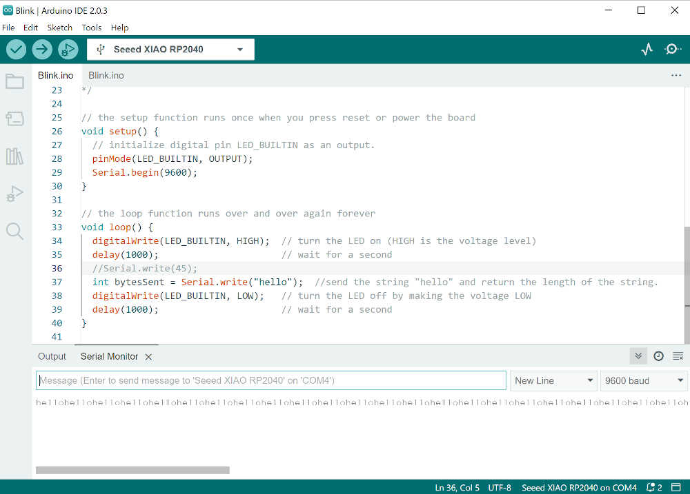
At first, I tried to get some output from the Arduino, so I modified the led blinking code so that the RP2040 would output the word "hello".
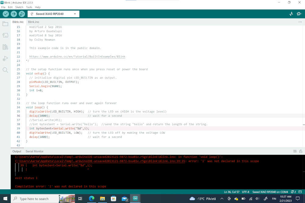
Then I tried to make the output change during the operation. First I encountered a problem: I thought that it would be enough to declare variable in the setup section of the code, but this was not the case.
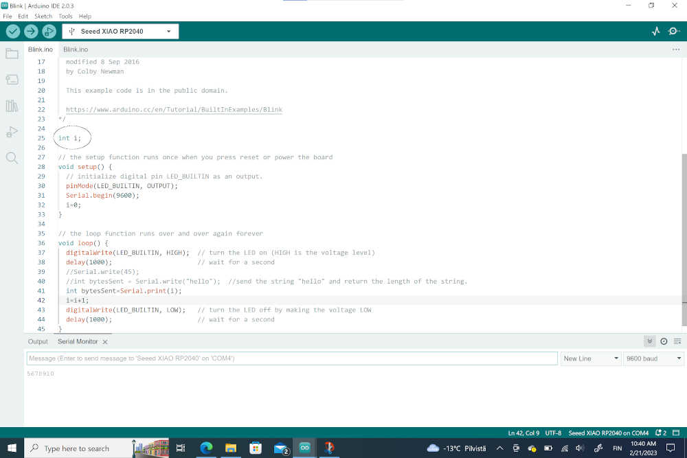
I then found that the variable should be defined already before the setup loop.
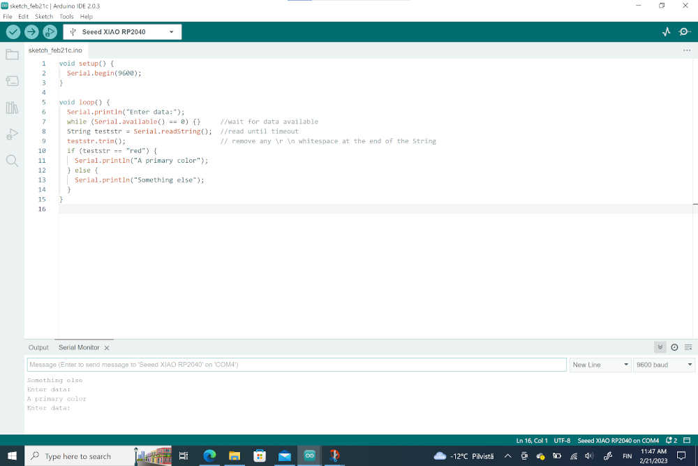
After these initial tests, I tried a codes which allowed me to interact with the board using the serial monitor.
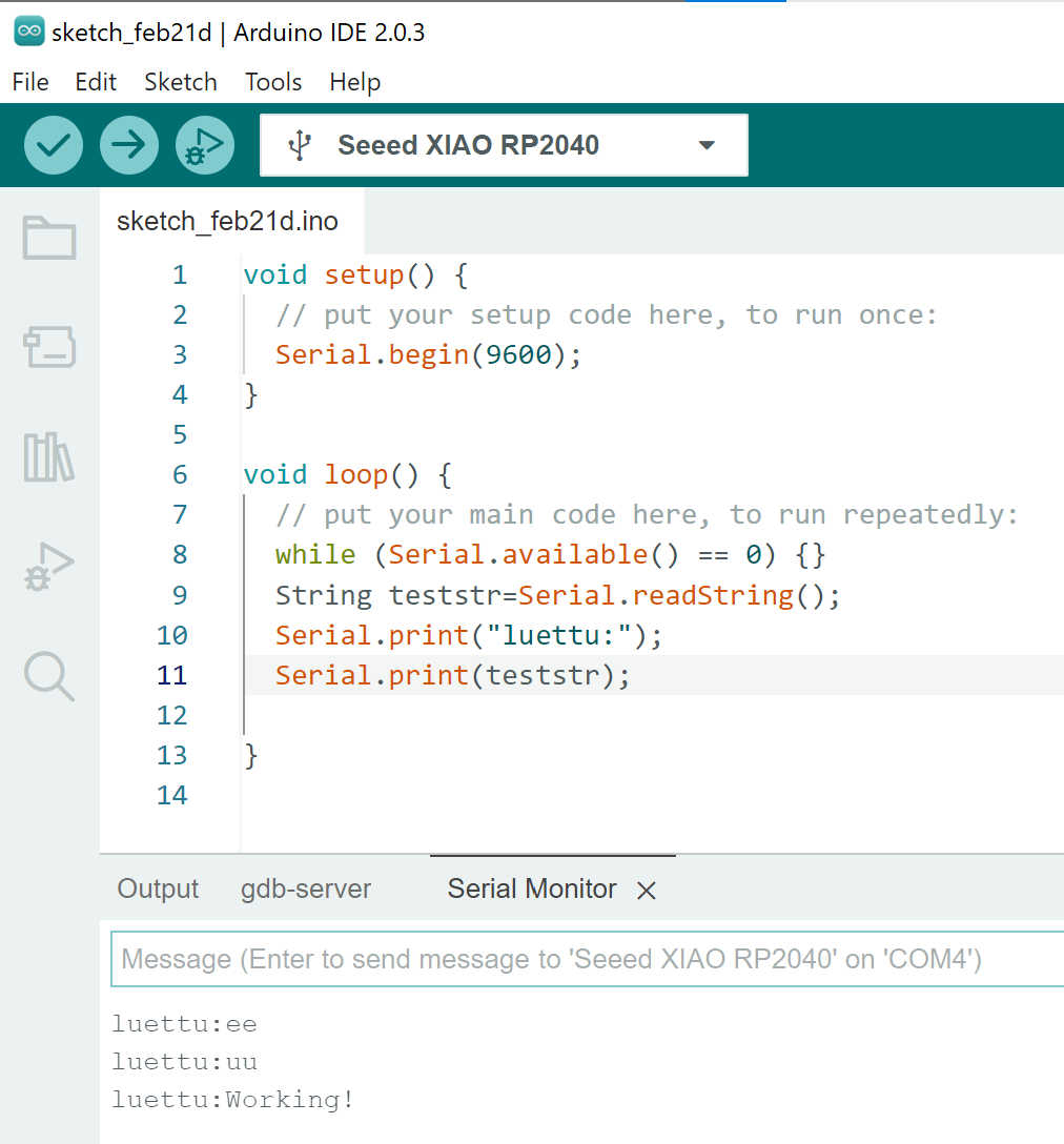
I made a similar code from scratch for interacting with the RP2040.
void setup() {
// put your setup code here, to run once:
Serial.begin(9600);
}

void loop() {
// put your main code here, to run repeatedly:
while (Serial.available() == 0) {}
String teststr=Serial.readString();
Serial.print("luettu:");
Serial.print(teststr);


}
The program was working when I tested it:
Using photoresistor to control led brightness
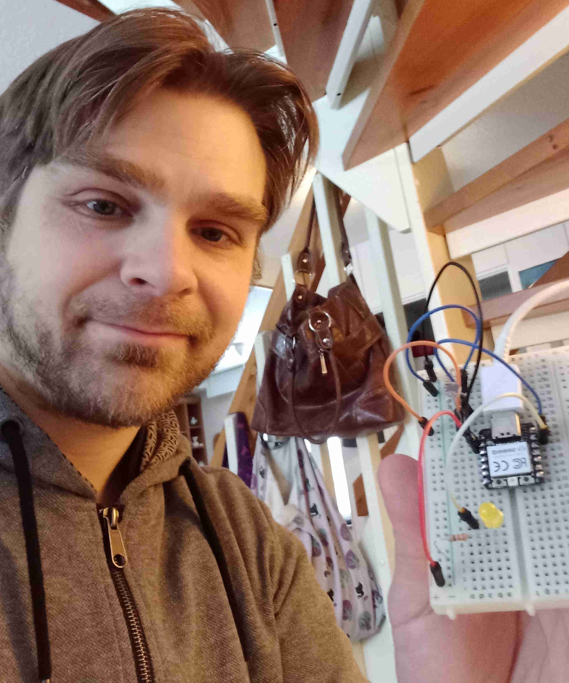
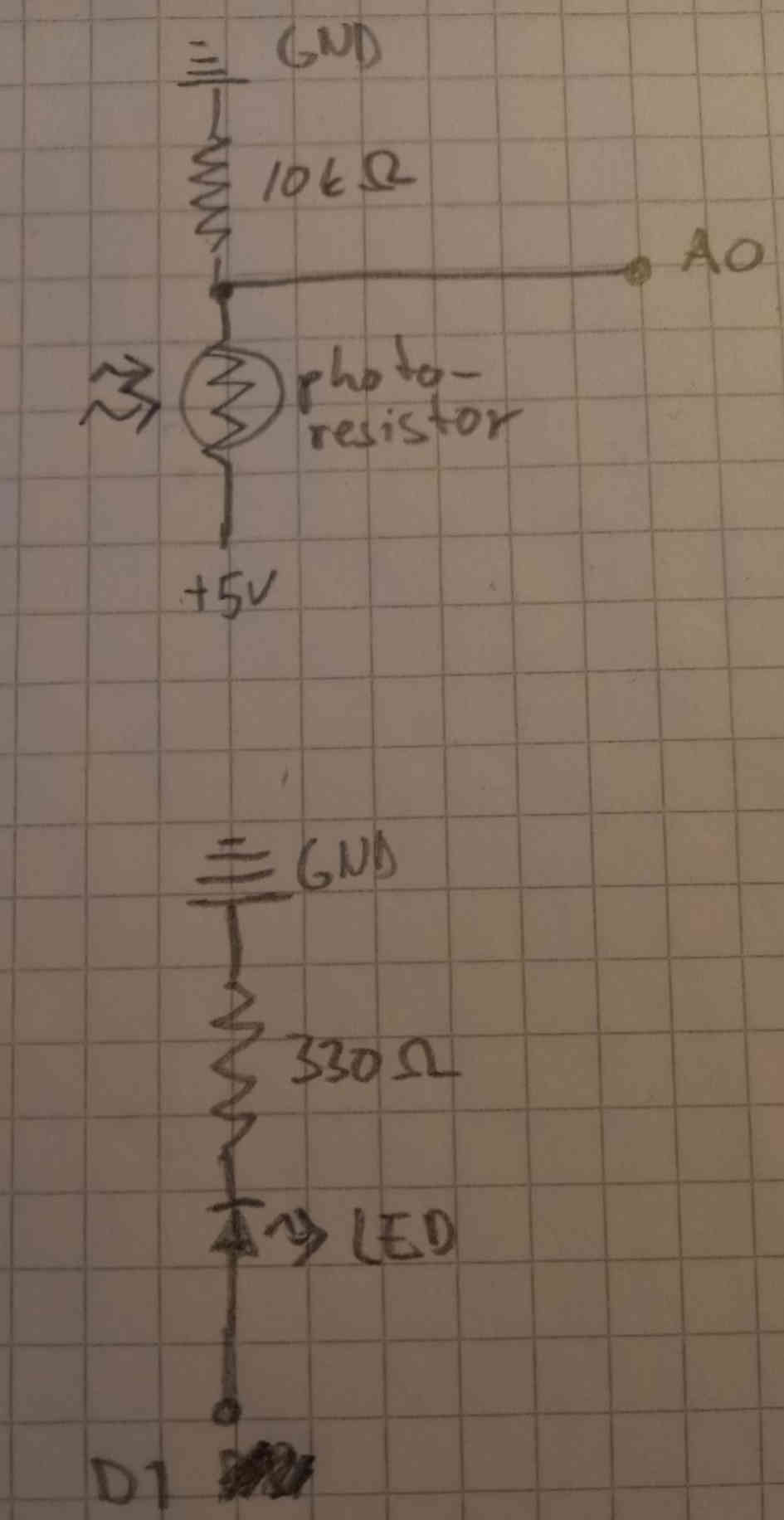
¶Next, I wanted to make my own circuit using breadboard and jumper wires. I thought to make a circuit which would consist of a led and a photoresistor. The resistor values and similar connection was described in the Sparkfun Inventor Kit, but I made the code myself instead of using the ready made code, although I got some ideas and function names from the inventor kit code. The idea would be that the photoresistor would sense the amount of light exposed to it, and the led would give an indication of the light level so that if there is more light, the led would emit more light, and if there is less light the led would be dimmer.
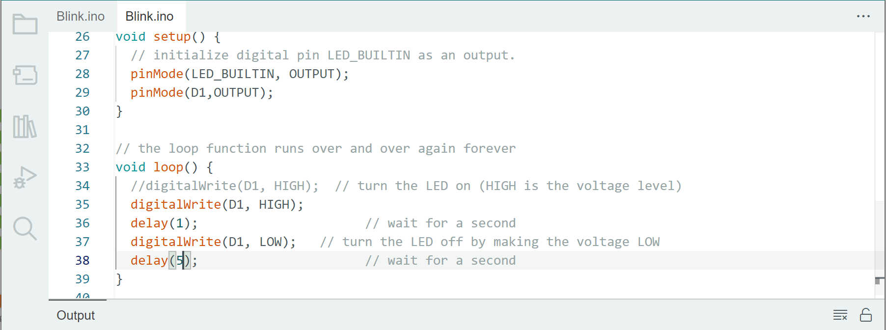
I started by connecting a led to the microcontroller board with breadboard and jumper wires.
To test that the connections worked I uploaded a simple test program to the microcontroller.
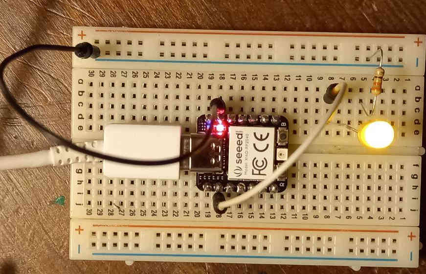
After this I added the photoresistor to the breadboard and connected it with jumper wires.
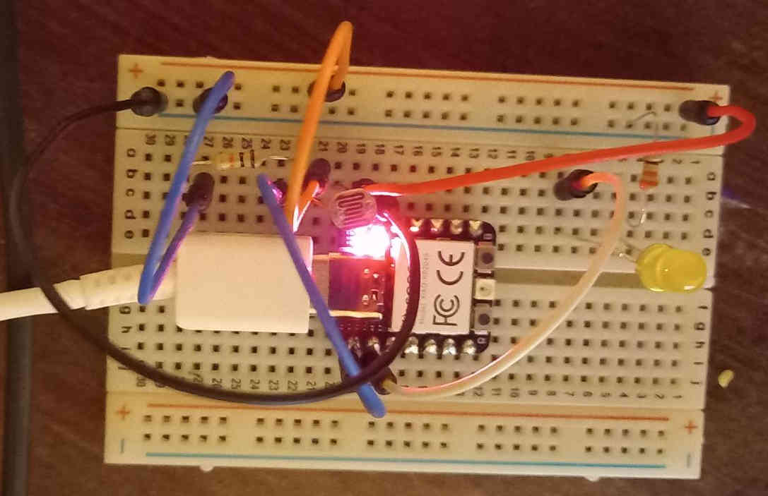
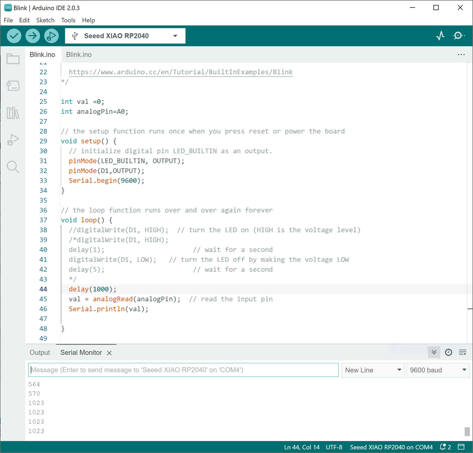
I uploaded a simple code to test the operation of the photoresistor.
After checking that the photoresistor was working, I changed the code so that the value read from the photoresistor can control the brightness of the led.
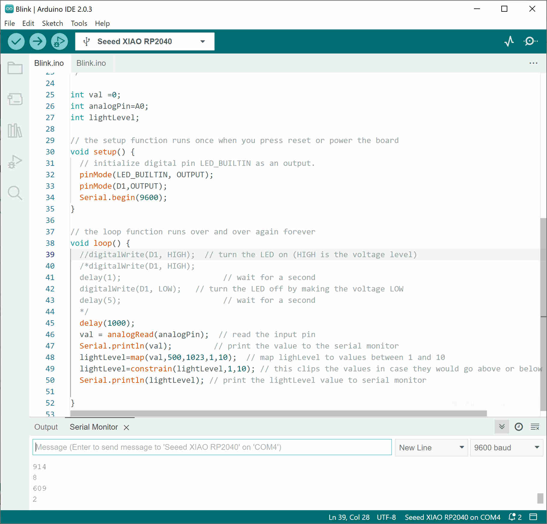
The final code for controlling the lighvalue with the photoresistor is below:
int val =0;
int analogPin=A0;
int lightLevel=1;

// the setup function runs once when you press reset or power the board
void setup() {
  // initialize digital pin LED_BUILTIN as an output.
  pinMode(LED_BUILTIN, OUTPUT);
  pinMode(D1,OUTPUT);
  Serial.begin(9600);
}

// the loop function runs over and over again forever
void loop() {
  //digitalWrite(D1, HIGH);  // turn the LED on (HIGH is the voltage level)
  digitalWrite(D1, HIGH);
  delay(lightLevel-1);    // wait for a second
  digitalWrite(D1, LOW);   // turn the LED off by making the voltage LOW
  delay(10-lightLevel);    // wait for a second

  //delay(1000);
  val = analogRead(analogPin);  // read the input pin
  //Serial.println(val);   // print the value to the serial monitor
  lightLevel=map(val,500,1023,1,10);  // map lighLevel to values between 1 and 10
  lightLevel=constrain(lightLevel,1,10); // this clips the values in case they would go above or below 1 and 10
  //Serial.println(lightLevel); // print the lightLevel value to serial monitor

}