Embedded programming. Group 2 Work.
Group members
Group work for week 4
In this group assignment, we learned about different tools for embedded programming.
We used three different microcontrollers all in the Seeed XIAO form factor. We first learned putting simple sample codes to those and later used the "ring oscillator" codes and measured the signal frequencies.
Programming the microcontrollers
We first load the program into microcontrollers. We used programs given by our instructor. Detailed steps of this process could be found in our individual documentation for this week as each one of us did one microcontroller.
We used these "ring oscillator" codes from Neil:
Pin connections
We first soldered microcontrollers (XIAO RP2040, XIAO ESP32C3, and XIAO SAMD21 with pin connectors. Then, we were smoothly able to plug it into the breadboard for a group assignment with ring oscillators.
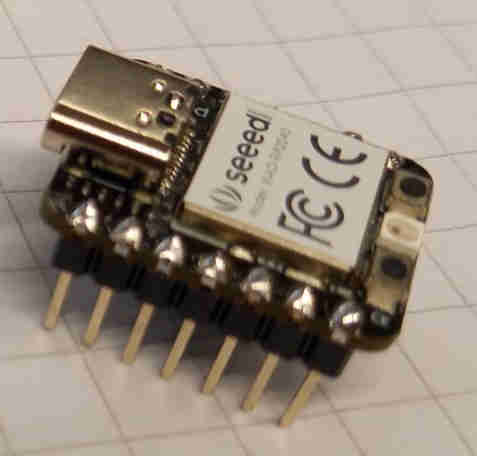 Figure: Example of a microcontroller board with soldered pin connectors.
The idea is to connect one input and one output pin together. In the programmed code the input will be read and the output will be set to the opposite boolean value. This will result in a square wave of which frequency we will measure with the oscilloscope.
XIAO RP2040
XIAO ESP32C3
XIAO SAMD21
The code for this was not presumably specifically for the SAMD21 but an earlier model. Therefore, there wasn't direct instructions on which pins to connect. From the rather complex looking C code we were able to figure out that the pins used were PA02 and PA04 which we found from the schematic. From which we saw that those pins were actually D0 and D1 which are labeled "1" and "2" in the physical XIAO board.
Measurements
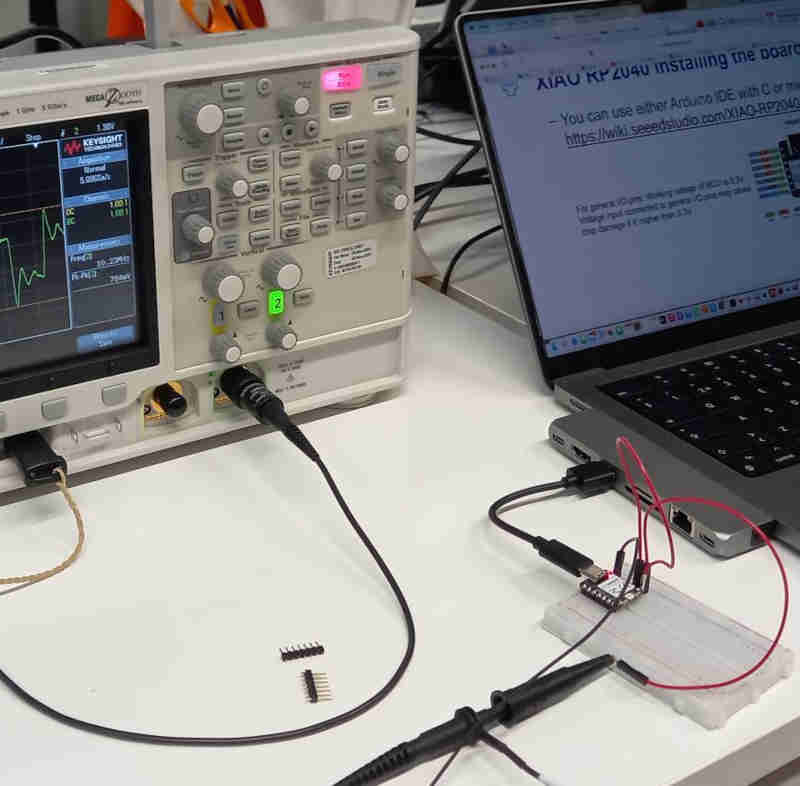
We used Keysight InfiniiVision DSOX3102A, a digital storage oscilloscope to measure the frequencies of the square waves.
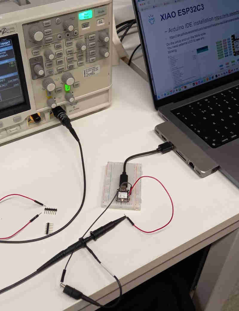
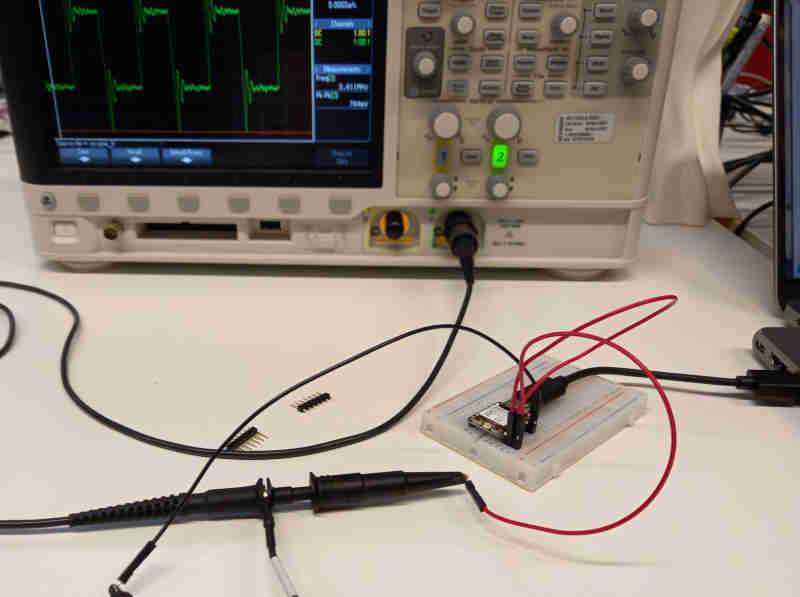
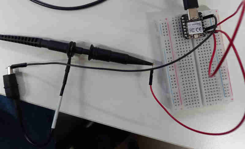
We used breadboards and jumper wires for the connections. The "input" and "output" pins are defined in the codes previously mentioned in this section. For each board, we connected the input and output pins together with a jumper wire. Then we connected the oscilloscope's measuring probe to the same jumper wire. Finally, we connected the oscilloscope probe's ground reference to the ground of the microcontroller.
Now we could power the microcontroller from the USB-C port and see the signal from the oscilloscope.
Images of the procedure
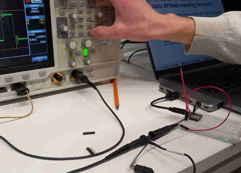
The following figures show how made the connection between the programmed microcontroller and oscilloscope.
Results
The following figures show measurements from the oscilloscope.
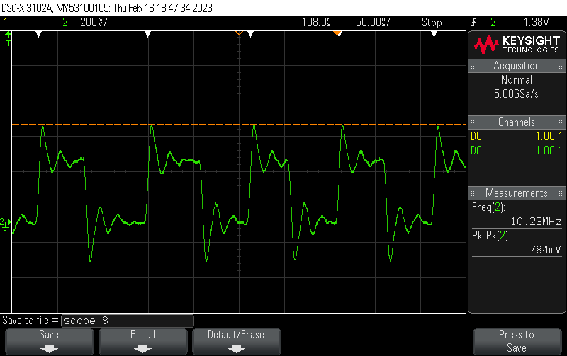 Figure: XIAO RP2040 measurements
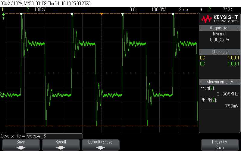 Figure: XIAO ESP32C3 measurements
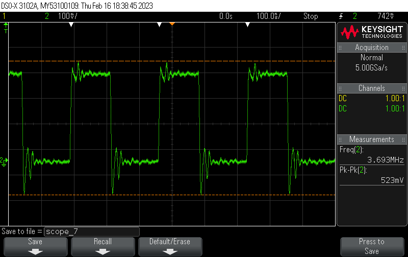 Figure: XIAO SAMD2 measurements
The signal frequencies for XIAO RP2040, XIAO ESP32C3, and XIAO SAMD2 are 10.2 MHz, 3.81 MHz, and 3.69 MHz respectively.
Since the processor clock speeds are different, it is interesting to calculate the signal frequency per processor speed. This is shown in the following table.
| read in-out speed (MHz) | processor speed (MHz) | ratio | |
|---|---|---|---|
| xiao RP2040 | 10.23 | 133 | 0.07692 |
| xiao ESP32C3 | 3.81 | 160 | 0.02375 |
| xiao SAMD21 | 3.69 | 49 | 0.07688 |
Table: Signal frequencies, the processor clock speeds, and the ratio of the signal frequency to the processor speed.