Electronics Production. Group 1.
Group members
Week 8 group assignment Electronics Production
Weeks assignments
This week assignment was to characterize the design rules for your in-house PCB production process.
Desingning boards
We used MODS to make files for the milling of our test pieces. We created and saved files of the circuit board traces and the outcut.
First we saved our test files (png) from Fab Academy pages (traces and traces outline).
In Mods (mods.cba.mit.edu) we created the toolpaths for our test design. We used a precompiled program and added a module for saving.
We right clicked for menu. Select Programs -> Open server program -> Roland Mill -> SRM-20 (our machine)-> PCB png.
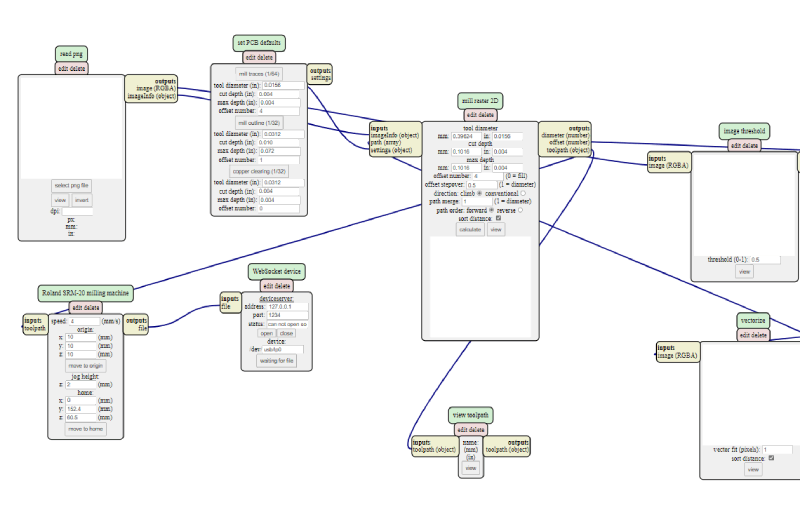
Picture1: MODS workflow for Roland SMR-20
We didn't need the Websocket module, so we deleted it. We wanted to save the output file locally, so we added a module. Select Module -> Open server module -> Save file. Then we had to connect the elements by clicking on Output of Roland machine SMR-20 and clicking on Input of save file modeule to make the connection between them.
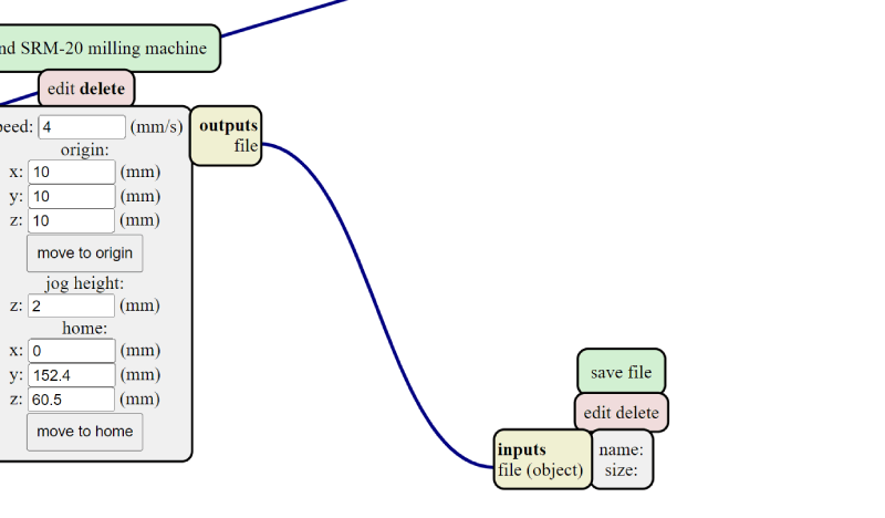
Picture2: MODS added new module for saving
We also set the milling machines coordinates x,ya and z to zero.
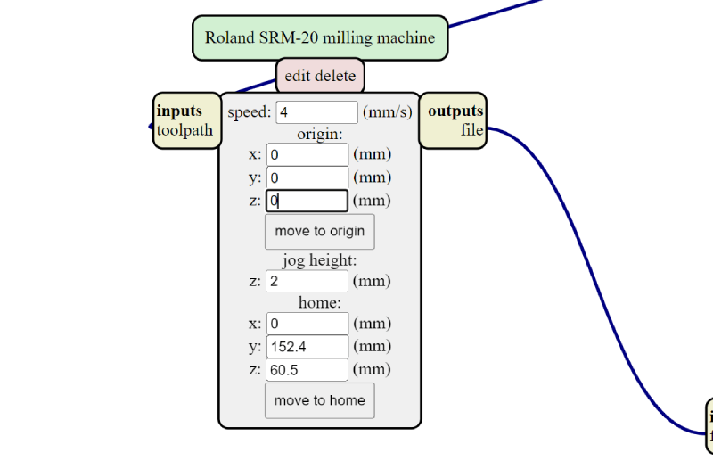
Picture3: MODS setting new origin point
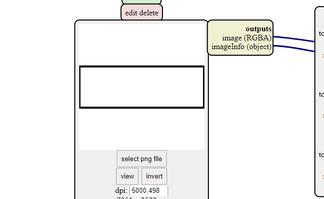
Then on the Read png module we aded the first of our designs in Select png file.
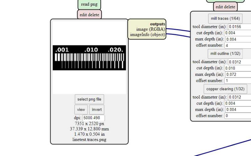
Picture4: MODS read png
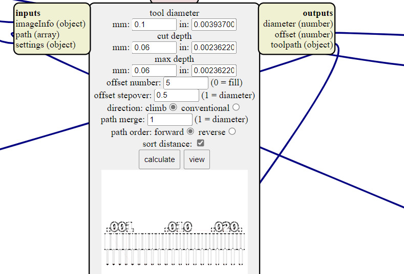
To Mill raster 2D module we changed the tool diameter to 0.1 mm, cut depth to 0.05 mm, max depth to 0.05 mm.
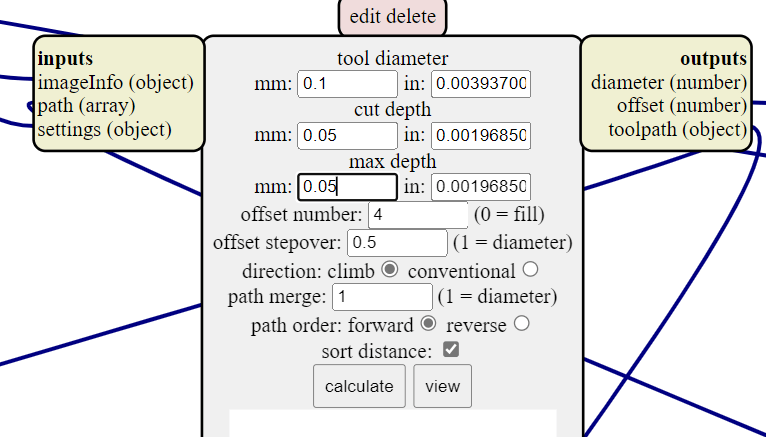
Picture5: MODS tool settings
Then we pressed Calculate. The file is automatically saved to download folder.
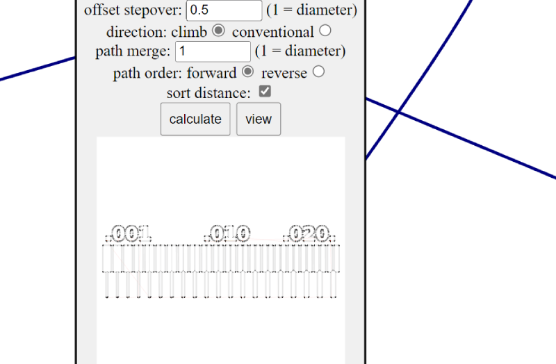
Picture6: MODS calculating tooling paths
From the View button we could observe the results more closely and check it looked ok.
Picture7: MODS view tool path module
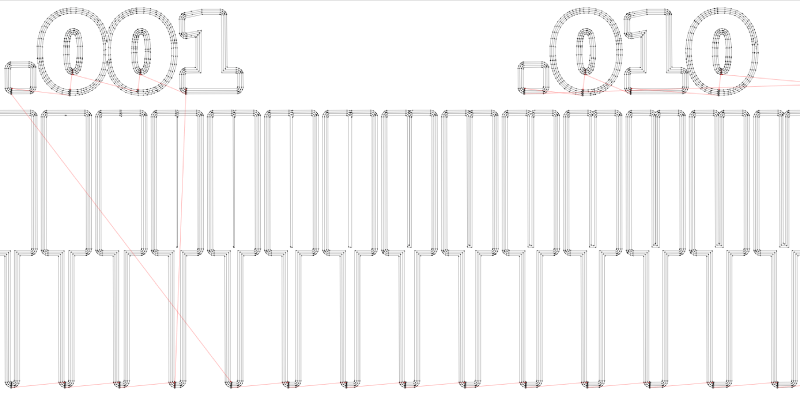
Picture8: MODS view of tool paths
We repeated the process multiple times by adding 0.01 mm in every step to both cut depth and max depth. Also offset number was set to 5 at this point.
Picture9: MODS creating different versions for cutting depth
Then we did the same steps with a tool diameter of 0.2 mm. Cut depths and max depths from 0.05 to 0.120 were calculated and the files saved.
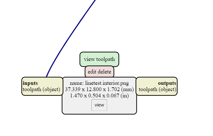
At the end we also loaded our interior file png. Tool diameter was set to 1, cut depth to 0.6, and max depth to 1.7 mm. Offset number was 1. After calculating, we saw the result in view and it looked good.
Picture10: MODS creating outline for the board
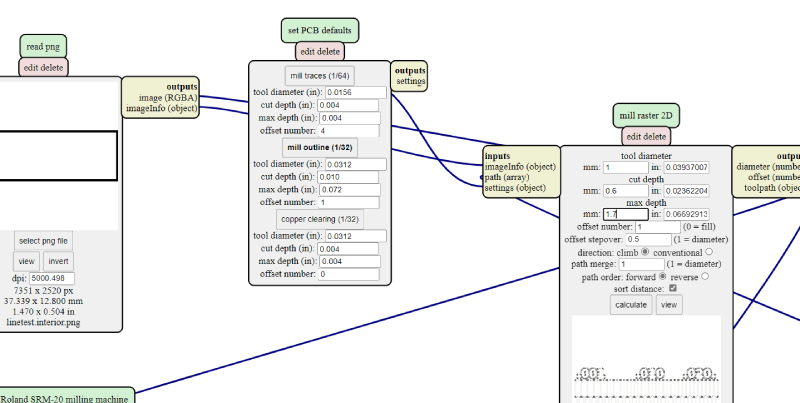
Picture11: MODS outline tool settings
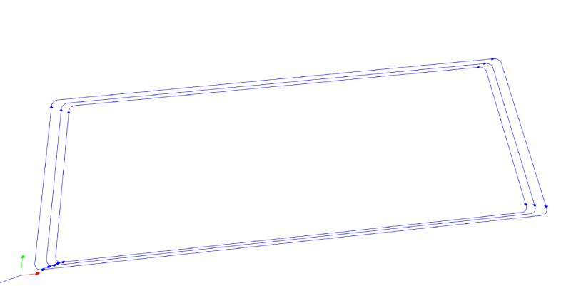
Picture12: MODS finished outline file
In the end, we had the outcome files for both tools (0.1 and 0.2 mm) with 8 different cut depths. Then we were ready to go to the machine!
Milling the boards
Our machine is Roland SMR-20 milling machine. Before doing our tests we looked that everything is tidy and the working surface is flat. We did some cleaning with a vacuum cleaner to make sure there was no dust etc. We also cut a piece of the material that we do our test with.
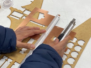
Picture13: Cutting FR-1 board
We checked that the board is not bent.
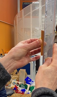
Picture14: Not bent
We then attached it to the machines milling surface with double-sided tape.
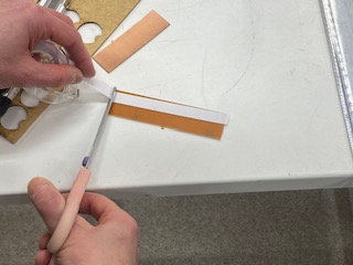
Picture15: Adding double-sided tape to the board

Picture16: Attaching board to the sacrificial layer
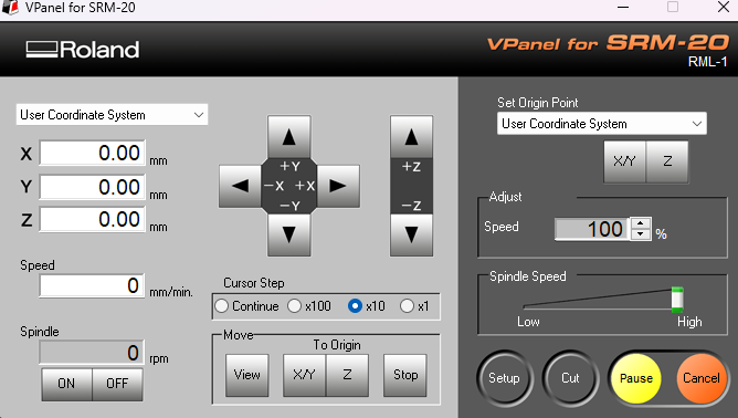
The program we used with the machine is VPanel for SMR-20. It's screen has the user coordinate system in which you can move the milling head, set origin, move to origin and adjust the speed and spindle speed. Also there are the buttons for setup, cut, pause and cancel.
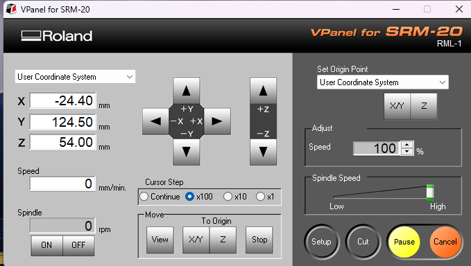
Picture17: Roland VPanel
We used the 0.1 mm and the 0.2 mm milling bits, v-shaped. To attach the 0.1 mm drill, we held it to the socket in the milling head and tightened gently the screw with a hex key tool.
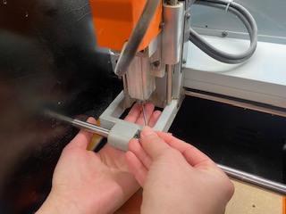
Picture18: Changing the bit
The first thing we did was setting the origin point. We moved the milling head with the program. We sent it to the left bottom corner of our material. The x and the y were set there by pressing the buttons (set origin point x/y).
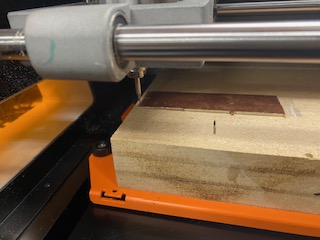
Picture19: Milling head placement
Then we moved carefully the milling head down closer to the surface. When it was fairly close, we loosened the screw and let the milling bit fall down to the surface by gently holding on to it. Then we tightened the screw again and now we were able to define this point as z origin.
Picture20: Origin is set
Then we downloaded our linetest traces file (rml). From cut popup window you clear earlier selections by selecting "delete all" and then add your current file. When you press Output the milling will start right away.
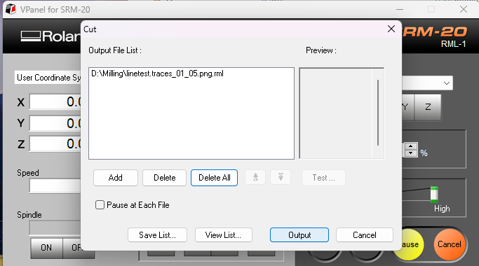
Picture21: Cut window
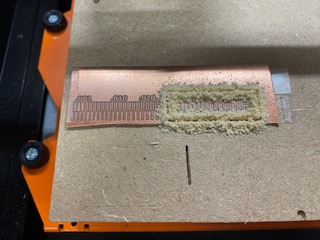
In our first test, some tape got in the way of our test pieces left edge. Otherwise the milling went perfect. The file was done with 0.05 cut depth. We cut the second piece right after this. Before that we changed the milling bit, set the z origin and moved the x/y origin 40 mm to the right.
Picture22: Second origin
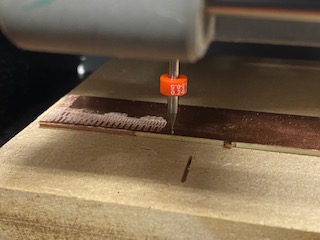
Finally we also cut the outlines to both our pieces, first to the second one and then after resetting the origin back to left corner, the first one. For that we had to change the tool to 1 mm milling bit.
Picture23: First outline after the cut
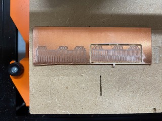
Picture24: Checking the result
When everything was done, we moved to the view and removed the milling bit. We cleaned the machine with a vacuum cleaner.
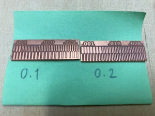
Picture25: Finished test pieces