Electronics design. Group 2 Work.
Group members
Group work for week 6
This week we tested a microcontroller power usage with a multimeter. We have previously demonstrated the use of an oscilloscope in week 4.
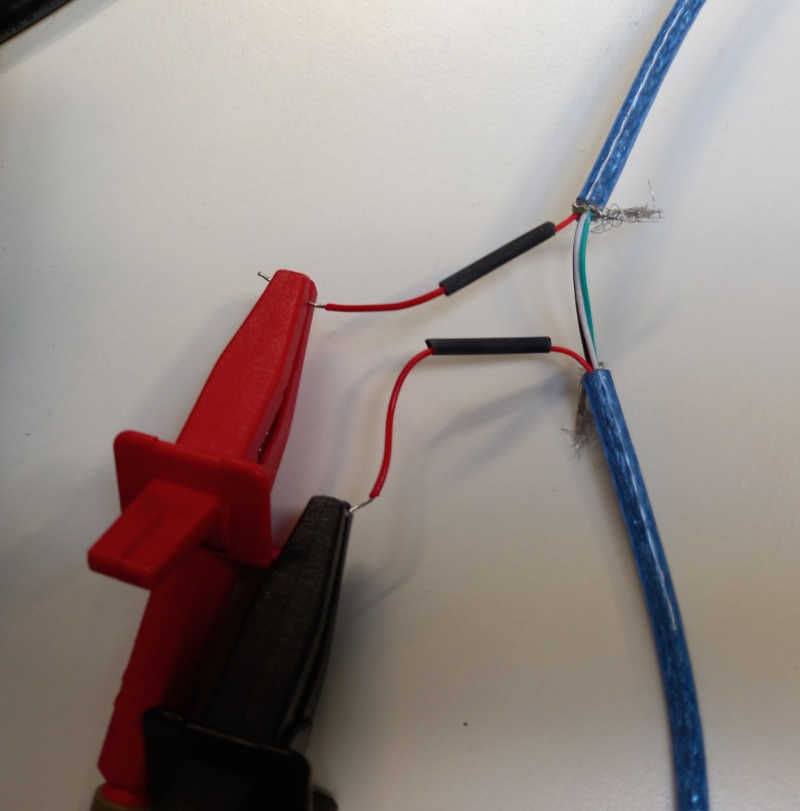
To measure the current we used a modified USB extension cable.
The voltage wire has been cut to allow connecting the multimeter in series.
This way we can use any USB power supply.
For testing the board, we uploaded Akseli's code written for the Seeed XIAO RP2040 in week 4.
The code has two stages that can be changed using serial communication.
- Blinks the on-board NeoPixel with two colors
- Blinks the small built-in LED on/off
We changed one color to be full white (255,255,255) to see the maximum power usage. The other color is a medium blue (25,25,180).
So in total four states ranging from both LEDs off to the full white NeoPixel. We measured the current for each of the states.
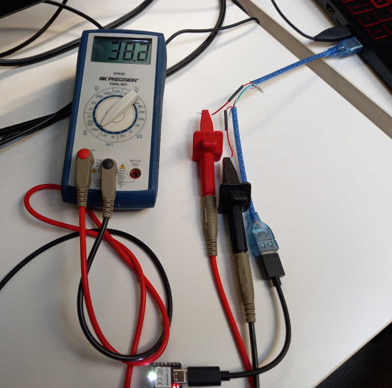
In the first one, the color of the neopixel led was set as bright white color
which drew highest amoung of current.
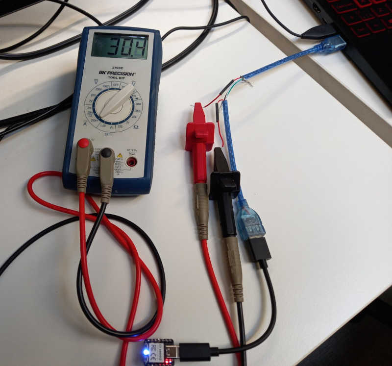
In the second one, the color of the neopixel led was set as blue color
which drew significantly less current.
In the third one, only the small built-in led is on
which is almost the same as the next state.

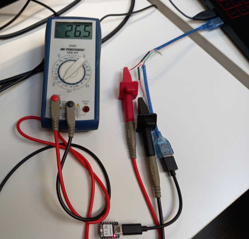
Finally, neither of the LEDs was on, which drew the least current.
| Measurement | Current (mA) | Voltage (V) | Power (W) |
|---|---|---|---|
| 1 | 38.2 | ~5 | 0.191 |
| 2 | 30.4 | ~5 | 0.152 |
| 3 | 26.8 | ~5 | 0.134 |
| 4 | 26.5 | ~5 | 0.1325 |