Electronics Production. Group 2 Work.
Group members
Group work for week 8
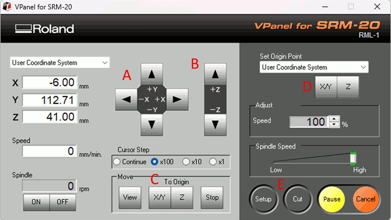
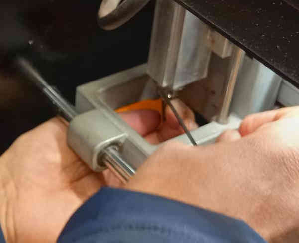
The Roland Milling machine could be controlled with the VPanel for SRM-20 program. There are controls for movin the milling head in x- and y- direcions and in z-directions, setting the origin and starting cutting. The procedure is 1. Attach milling head, 2. Move the milling head to x- and y- origin. 3. Set x and y origin. 4. lower the milling head next to board (so it does not touch the board but is very close). 5. Loosen the milling head with hex key and lower it manually on the board. 6 set z origin. 7. raise the milling head a bit and 8. select cutting program and start cutting.