Computer Controlled Cutting. Group 1.
Group members
Week 3 group assignment Laser cutting
First task of the day
The day started with Fablab Oulu bigger laser cutter (Epilog laser fusion 75 watt CO2 ). First task was to cut test piece to measure kerf. We used premade settings for the material(HDF 3mm) Speed 12, Power 100 and Frequency 20. We used same setting for default starting point for all the tasks, with this laser cutter.
When we were measuring finished piece with caliper, we noticed that cube sides were different. So we run the test again and marked the cut piece orientation. With this test we were able to calculate kerf.
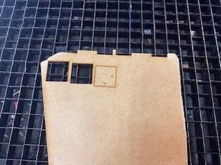
Picture1:Orientation marked on the cutting bed
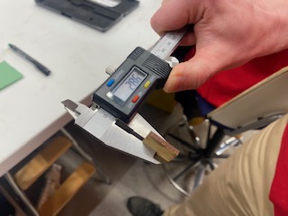
Picture2:Measuring material thickness
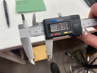
Picture3:Measuring X axis
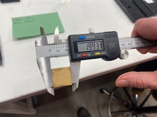
Picture4:Measuring Y axis
We calculated kerf with following formula kerf = designed width - measured width
Second task of the day
Second task for the day was to test what effect laser focus is playing in the cutting process.
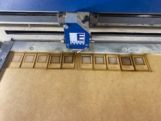
Picture5:Cutting and engraving test pieces
When we were running the test we noticed that used material (3mm HDF) and Laser cutter materials setting (3mm MDF) were different. So we had to change settings for correct material and run the process again. Tested focus points were 1mm above/below and 4mm above/below. Material we used was 3mm HDF.
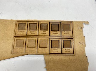
Picture5:MDF vs HDF setting in HDF
1 mm below there was variation in the engraving so it is not even. 1 mm above the text is ok but isn't as clear as in 1 mm above.
When focus was 4 mm above the laser didn't cut through the piece. 4 mm above ja 4 mm below are both a bit burned up and don't look so nice. The best combination though is the first one!
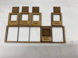
Picture5:Cutting and engraving test pieces
Laser beam does not cut when it's 4 mm above because the beam doesn't hit material surface in optimal height.
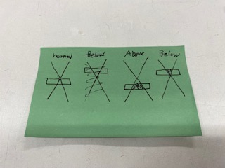
Picture5:Focus point in a cutting plane
Third task raster images
For this task we changed power and speed settings to test engraving quality on raster image.
The default values for Raster setting: power(P) 100 and speed(S) 80. Material is 3mm Plywood. Power was adjusted to 3 pictures above and speed was adjusted to 3 ones below those.
- Power set to 70%. The engraving quality lightens up just a bit compared to default values.
- Default P,S
- P40 is really light.
- Speed set to 90% results in very small difference in depth and level of detail of the engraving.
- S40 when laser moving speed is slower, engraved parts start to darken more.
- S20 when speed is this slow, cutting piece is already starting to burn.
It can be clearly seen that with less power, the engraved parts are lighter than those of stronger power.
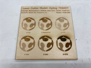
Picture5:Different settings for the raster image
Fourth task Vector testing
Settings for the vector P100 S12
Firstly, we keep the Frequency constant, and adjust first the Speed and then Power.
With P100 S12, S7, S17, S30
With slow speed the laser works well in cutting through. Until the speed is increased to 30%, we observe that the cut doesn't happen.
With S12 P100, P80, P20
With lowering the power a small change does not affect, but P20% is too little and it doesn't cut. So basically for cutting the power settings could easily be only 80% and still it would cut fine.
With changing the frequency there is no affect (P100, S12).
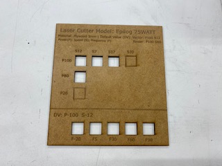
Picture5:Different settings for the vector image
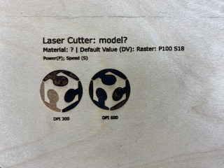
Fifth task DPI test
We tested how DPI settings affect the engraving.
We used the smaller laser cutter (Epilog laser mini 60 watt CO2) for our DPI testing. Setting used were for raster Speed 50, Power 40.
At first we used plywood and when cutting there was a clear flame so that was not good. One of our instructors cleaned the laser, and we also changed the material to HDF in this point. After that it worked out fine.
Picture5:Failed test piece
DPI means dots per inch.
The less DPI we used the the lighter the outcome of the picture was. Bigger the DPI is the deeper and therefore darker the picture and the engraving also takes more time. There is no right or wrong value for the DPI setting. DPI value depends of what you want to achieve and what you like.
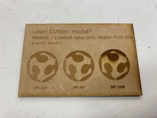
Picture5:Testing DPI
Sixth task Press fit pieces
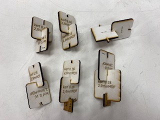
For using parametres and checking also our measured kerf, we did some exploring with pieces. We cut some pieces that were already desingned by our instructor. At first we didn't take into account kerf in a parametre called slotwidth and after cutting the slotwidth was bigger than it should.
Next time we added the kerf to the parametre as: slotwidth = slotwidth-kerf. When we cut, the was fit was now very tight but we did get the pieces together. Overall the edges easiest to put together, were the ones with chamfer on it. Also with those the material doesn't break so easily.
Picture5:Drop test for second pieces
We discussed what could be made differently to have just the perfect size measurements. The kerf we measured initially (0,22) sounded a bit big to begin with. The last test pieces we made were really tight fit, so little smaller kerf might give better result. It is good always to cut a small test piece when you start a new project and check for the kerf. Then remember when to add the kerf and when to reduce it.
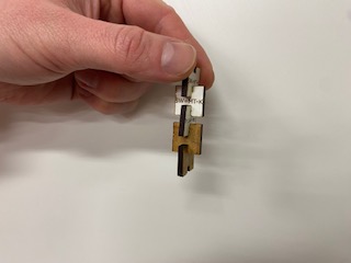
In the end we examined some example pieces that were found in the lab. In the last image our instructor is demonstrating model with series of identical slots and how the cuts are lightly varied.
Picture5:Kerf example pieces from the lab
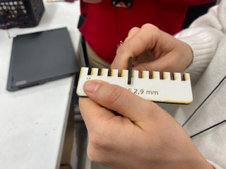
Picture5:Differences on series of identical cuts