Computer controlled machinining. Group 2 Work.
Group members
Group work for week 7
We begun with a lecture recapping the machining principles and proceeded with our machine specific stuff.
The processes are documented with more accuracy and depth in the individual pages.
Machining
Our instructors demonstrated the process by milling a clothes hanger from plywood. Later we measured the piece to see if it fits specifications in the design.
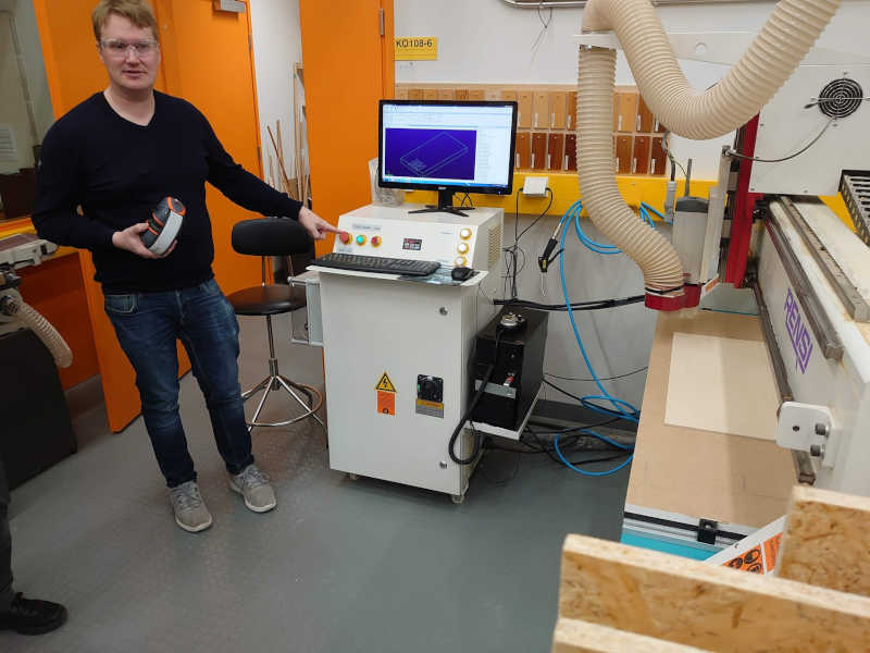
Figure. Here we are given the safety talk.
Main points about the safety:
- Operate the machine only when well rested and focused.
- Make sure you know how to stop the machine before starting.
- Stay outside of the machine's perimeter when it's running.
- Observe the operation the whole time and don't hesitate to stop it if needed.
Fixturing
In our machine we have a vacuum table which makes it really easy to hold especially the larger sheets. On the otherhand even though it's sacrificial, we don't want to unnecessarily wear the table. That's why the Z height is zeroed on the table (bottom of the stock) instead of the top of the stock sheet as seen below. This has to be taken into consideration also when making the toolpaths.
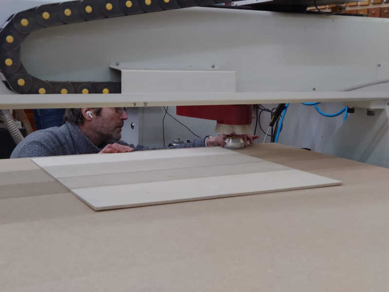
Figure. The Z height is being calibrated.
The plywood was a little twisted which made it difficult to get sucked onto the table.
For smaller pieces those are usually screwed on a larger sacrificial piece that sucks onto the table. Porous materials can also be difficult.
About materials and speeds
During the machining we begun with slower (80%) feedrate to see that there are no resonance sounds. The OSB board that would be used for the individual assignments is so soft that there it's unlikely. However, this birch plywood is considerably harder and therefore it's a good idea to start slowly. In the end there was no issue when the speed was increased to 100%.
Measuring the results
We measured the outcome to compare those to the design. The measurements are presented in the table at the end of the page.
Due to having set the Z height incorrecly (vacuum was not on when zeroing) The pieces were not cut all the way through. However, that doesn't matter for us as we can still take the measurements.
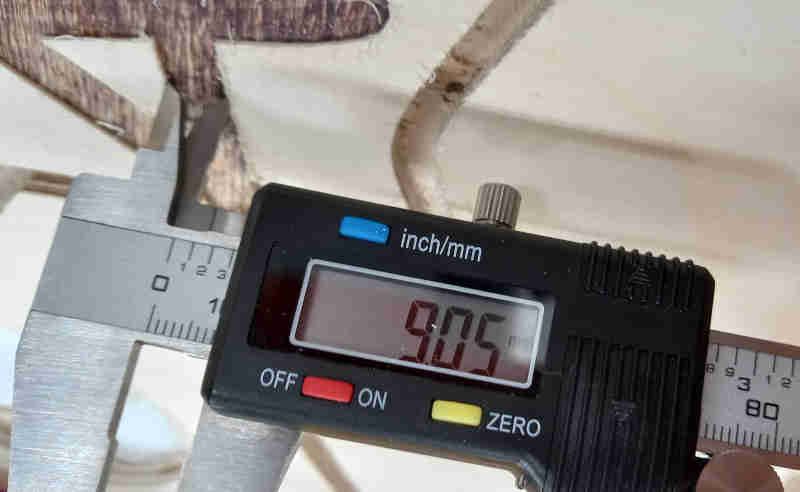
Figure. The width of the gap in the letter.
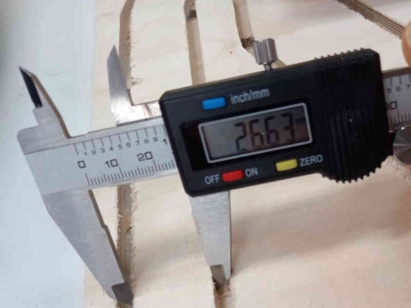
Figure. The width of the bottom beam.
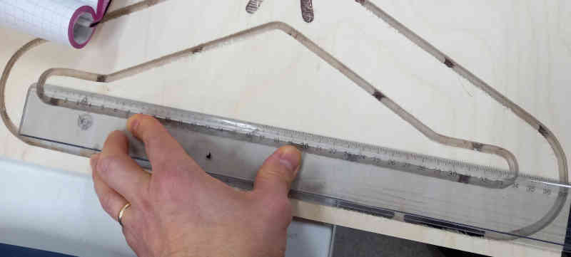
Figure. The width of the inside opening.
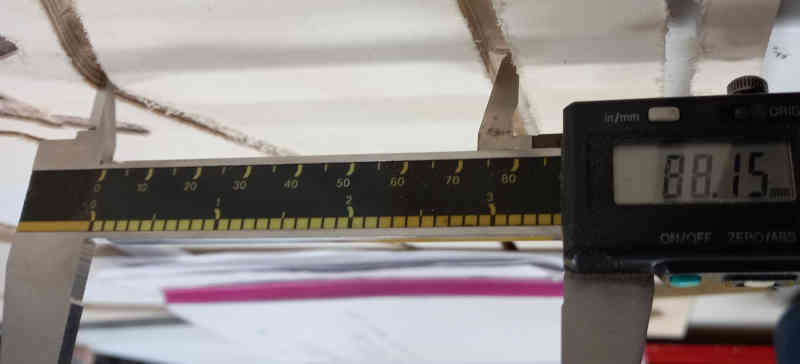
Figure. The height of the inside opening.
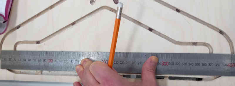
Figure. The outside width of the piece.
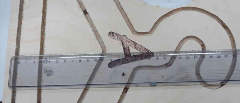
Figure. The outside height of the piece.
Table of the measurements
Our instructor provided the values used in the design.
| Region | Measured Extents | Designed Extents |
|---|---|---|
| Outside | 40.0 cm x 27.9 cm | 40.0 cm x 28.0 cm |
| Inside opening | 33.5 cm x 8.815 cm | 34.82 x 8.84 cm |
| Bottom beamwidth | 26.63 cm | 26.4 cm |
| Letter A horizontal beamwidth | 9.05 cm | 8.7 cm |
Majority of the differences in the measured versus designed dimensions are most likely due to inaccuracies with the measuring.
Although parts of the milled plywood can look burned in the pictures, it's actually the glue as this plywood was "exterior plywood".