Electronics design. Group 1.
Group members
Week 6 group assignment Electronics design
Measuring current of the development board
In group assignment 1 (week 4) we measured with an oscilloscope and the results can be seen here.
This week we used a multimeter to measure current of Seeed XIAO RP2040 development board. The multimeter we used was BK Precision Tool Kit 2703C.
Test setup: Our instructor prepared for us the cabel set up, so we were able to measure the current the RP2040 was using. The current draw was so low, that we used the mA setting from the multimeter.
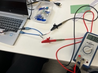
Picture1:Test setup
We opened Arduino IDE, connected the board to computer and selected port.
Test 1
First we measure the value when we had connected the board but it's not running any task. We got a reading of 32.0 mA.
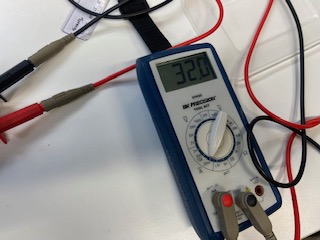
Picture2:Test 1 result
Test 2
We uploaded code for blinking the RGB LED from how2electronics tutorials here. The program makes the RGB LED blink with five differents colors. When we check for the values, we got a reading that was varying according to differrent colors between 29.5-36.8 mA.
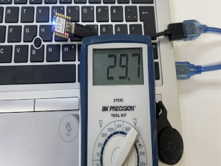
Picture3:Test 2 result
Test 3
We opened the built-in example code for blinking the user LED. We got a reading that varied between 25.3-25.7 mA. The highest reading 25.7 mA appeared when the LED was ON.
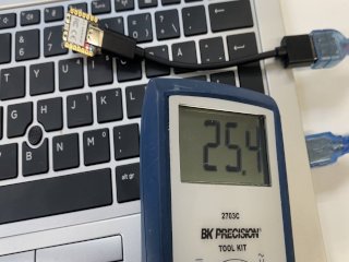
Picture4:Test 3 result
Test 4
We uploaded the code for ring oscillator test by Neil Gershenfeld that we used before with oscillator measurements. Functionality for the provited code was writing value to one pin and read from another. The pins are connected and value inverted in a loop. We got a reading of 33.8 mA.
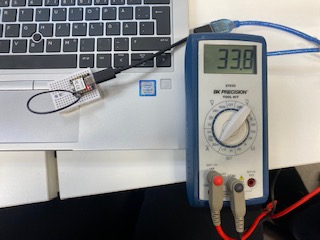
Picture5:Test 4 result