Teppo the Gripper
Group members
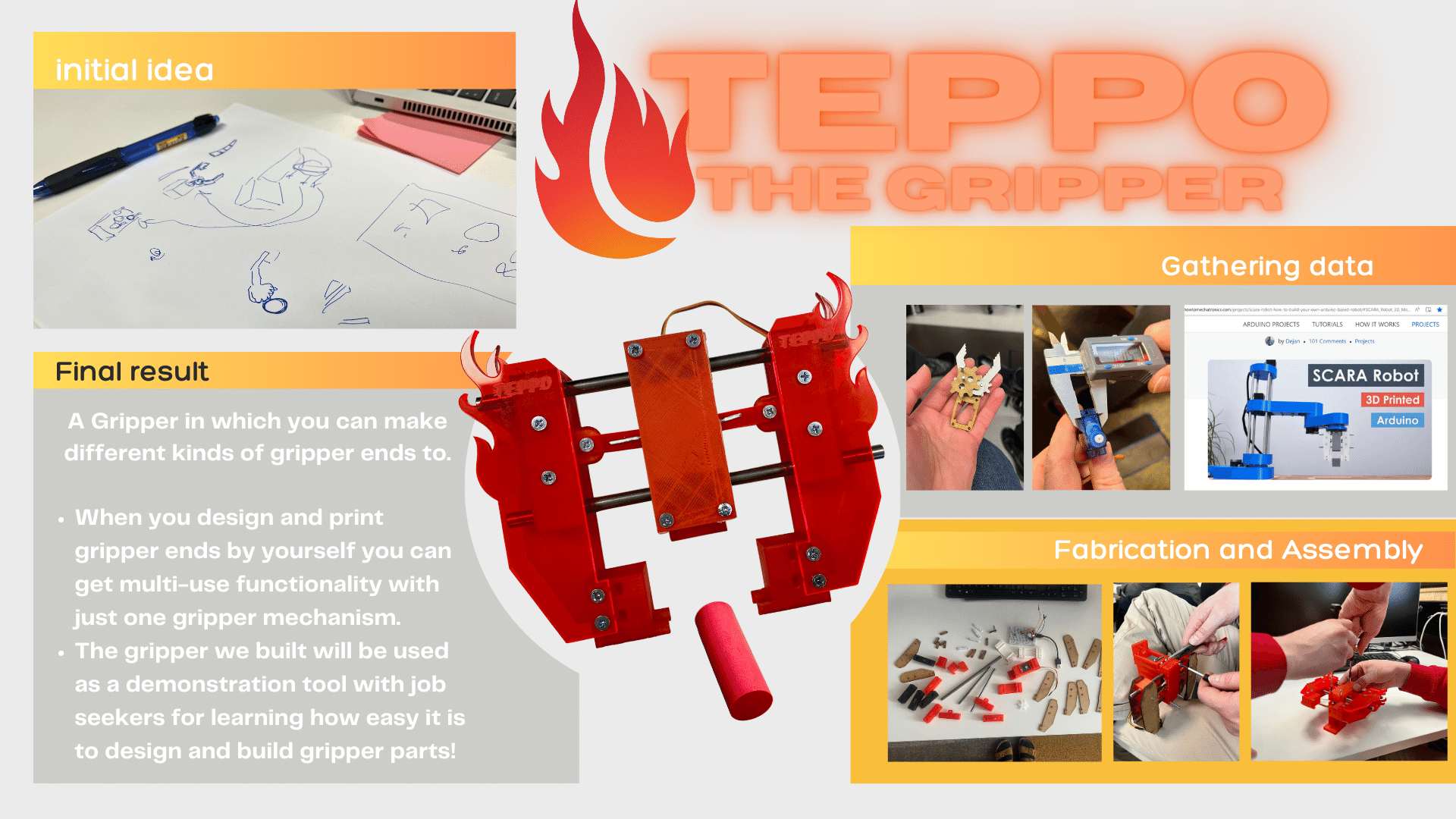
Teppo the Gripper
Brainstorming idea for the machine
This weeks local class started with our instructor describing that this weeks topic was huge, and it would actually take years of study to learn machine design properly. To that note, we started brave and not scared at all.
Fortunately, Tapio had already thought about an idea. They are planning a project at Business Asema, that would give possibilites for job seekers to learn how to design and fabricate their own gripper parts, especially the end parts. For that purpose, we thought it would be good to make a prototype of a gripper.
Research
Making of MeArm for demonstration purposes
Tapio already had some knowledge of grippers, but escpecially Petra and Essi wanted to see something tangible to understand the mechanisms needed. We searched the internet for grippers and especially projects that could help us to a start. One that we found and looked interesting was this Pocket size robot arm MeArm on Autodesk Instructables page here.
We were interested in the gripper part of the arm. We read the project documentation and decided to make a test piece for ourselves. As this was to be only a test for the purpose of understanding, we just downloaded the parts from Ultimaker Thingiverse here. We opened the pdf in Inkscape and modified the line thickness for laser cutting. We laser cut the parts from MDF. By looking at the project documentation, we did a quick assemble of the main part of the gripper.
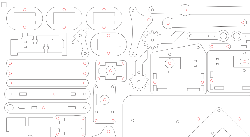
Picture1: MeArm gripper pattern
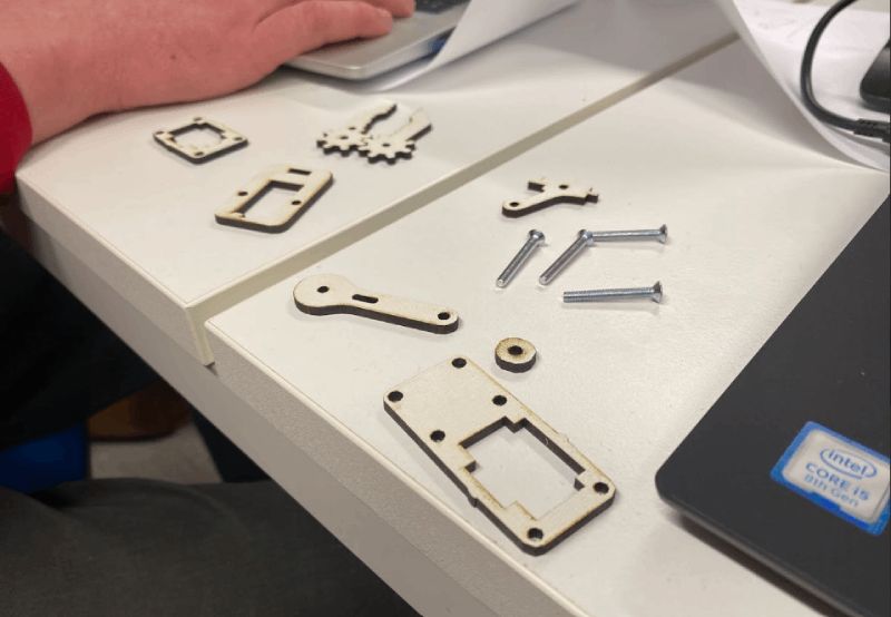
Picture2: MeArm gripper parts
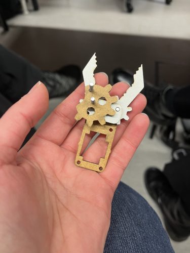
Picture3: Assembled MeArm gripper
Idea of scara type robot gripper
It was working fine. We got the idea, and initially thought we could work on this kind of model. But then we thought we could have a more suitable gripper for our purposes. After some reasearch, we found this very nice Scara project from howtomechatronics.com here. It is an Arduino based robot. We were again interested in the gripper part. As we got to know the project we decided to assimilate something like this in our project. The gripper is driven by servo motor, and it is easy to change the gripper ends to suite different needs.
Task assigments before next weeks first test
We talked about our design, the goals and what should be made to make the machine to operate. We looked into our individual skills and devided some tasks before we would meet again in a few days. Tapio who has skills in programming, was assigned to write code for using the servo. Essi and Petra were assigned to design and fabricate the parts for the machine, that would be either printed or laser cut. We also needed to buy the steel bars and some screws or bolts and Tapio got them from the store.
The parts that needed to be made were: the gripper hands, the gripper end parts, the links, the casing for the servo, and the box parts connecting the hands to the servo. The steel bars go throuhg the casing and the box parts.
You can look at the individual work we did from each of our web pages. Tapio's page here. Essi's page here. Petra's page here.
First test assembly of assorted pieces and testing the code
When we got together next week we had parts and code that we could assemble and test the first demo. At this point we were using smaller SG90 servo motor and thicker 10 mm steel rods. We used breadboard and jumper wires to connect test pieces.
We noticed that the links are too long for optimal gripper movement and steel rods were too heavy for the demonstration purposes.
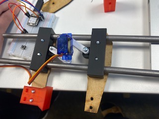
Picture4: First test assembly
More modelling and new batch for printing
We needed to model new slider bodies for thinner 6 mm steel rod. We decided to cut new links with laser cutter, because it's faster than 3D printing. Links thickness was close enough with the material that was available.
In this point Tapio also bought more screws and metal wire for attaching the links.
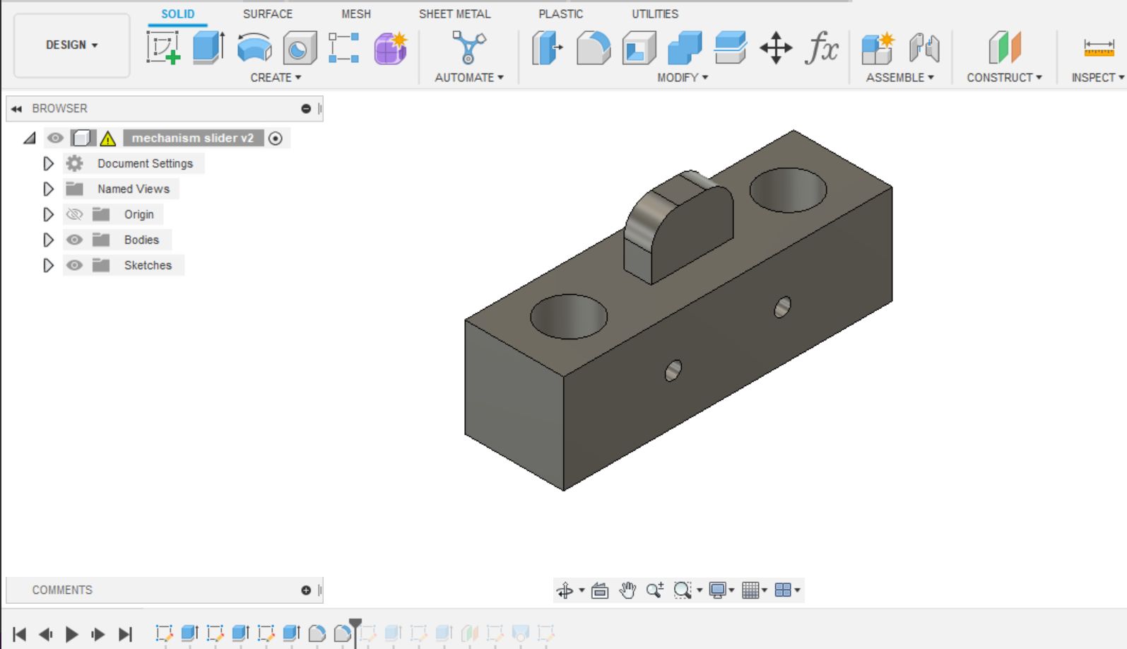
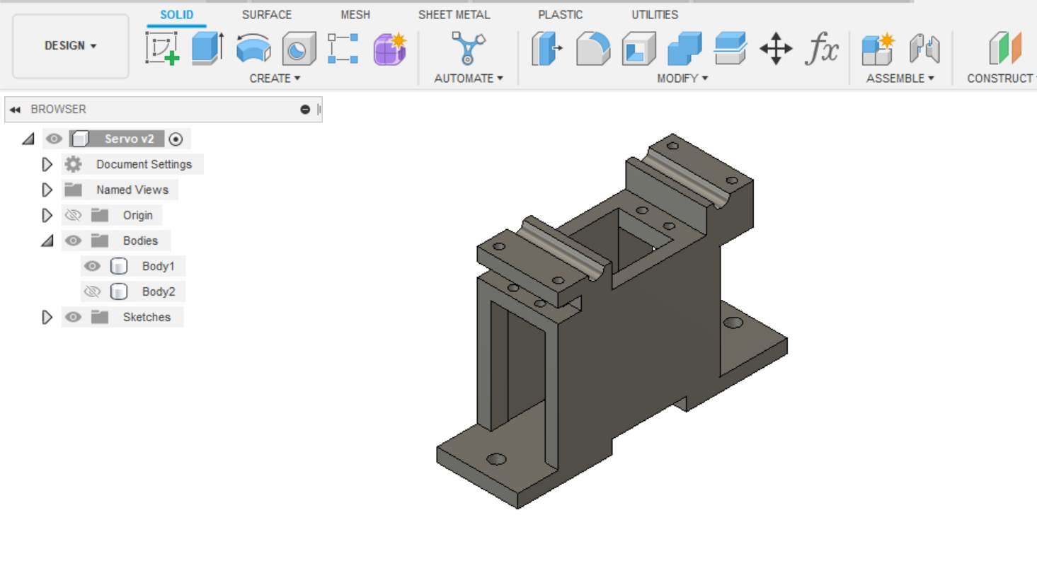
Picture5: Modelling slider body
Testing new pieces and bigger servo motor
Next we tested new pieces and bigger servo motor HK 15138. The links we cut were now too short for this servo and we measured that links are good if we add 6 mm to lenght.
We increased rod spacing in slider body to accommodate the bigger servo motor.
We also noticed that slider panels would work better for our purposes if the connection to end parts moved little bit more to inside of the design.
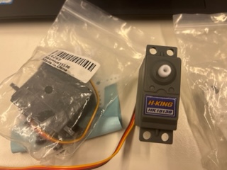
Picture6: Servo motor HK 15138
Picture7: Second assembly
More modelling
We modified the designs and modelled the body for the gripper. Then we cut and printed the new parts. 3D printers worked whole night!
Picture8: Modelling the body
Test assembly
Next morning we had all the pieces ready and we were able to test whole assembly for the first time.
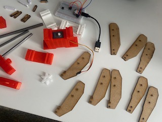
Picture9: Pieces
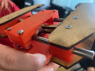
Picture10: Third assembly
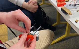
Some problems occured... The way we had to attach links to the slider body caused problems. As we did not have small enough screws for the links we had to use metal wire and bend the ends. Therefore main body was too high to accommodate the links.
As we wanted to finish assembly and printing time for the main body was so long, we decided to manually modify the body by filing.
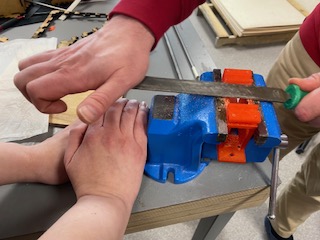
Picture11: Filing
We also added some washers between the servo links and slider connection to reduce link angle to ensure smooth movement.
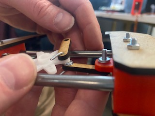
Picture12: Adding washers
Final pieces and assembly
The assembly worked so we decided to modify gripper's visual appearance. We designed new flaming panel pieces for the sliders and cut them and links from acrylic to better suit for the color theme.
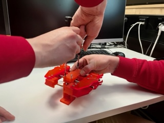
Picture13: Building the final assembly
At this point Tapio connected gripper to MCU via breakout board and modified the code to accommodate the button on the board.
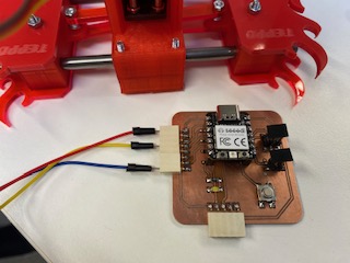
Picture14: Connecting to breakout board
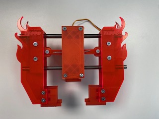
Picture15: TEPPO IS READY TO GRIP
We named this master piece Teppo the Gripper. In the presentation video you can see Teppo dancing. ;)