Computer Controlled Cutting. Group 2 Work.
Group members
Group work for week 3
Cutting a test piece and measuring the dimensions
First we laser cut a 20.0mm x 20.0mm square. However, closer inspection reveals that is not what we get:
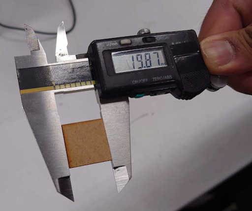
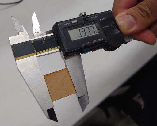
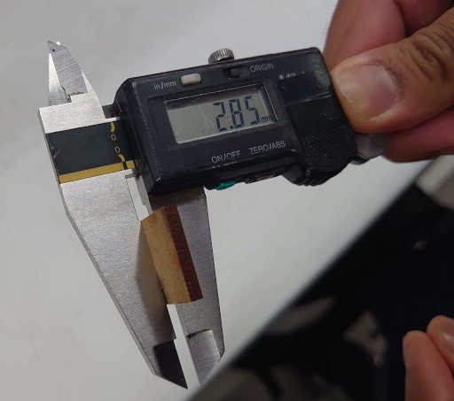
drawing: 20.0 mm x 20.0 mm
measurements: 19.77 mm x 19.87 mm x 2.85 mm
From this we can calculate the kerf. It is the theoretical width - measured width, which for this material was 0.18mm.
Testing to change the focus of the laser cutter
We tested the change the focus of the laser cutter. First we set the optimal focal point using a tool with the laser cutter. We changed the focus 1 mm above and below the optimal focal point, and also 4 mm above and below the optimal focal point. The results are shown in the Figure 1. We first used settings for MDF material but later we realized that the material was actually HDF, and we changed the settings. As can be seen from Figure 1, there is little difference but we used HDF setting from that point on.
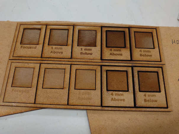 Figure: HDF setting used for above and MDF below (both materials are HDF)
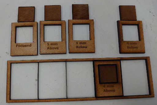 Figure: Varying focus height
We can see that going too far with the focus causes excess burning. Even still, others were cut through but not the 4 mm above. Maybe the next figure explains why:
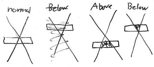 Schematic figure
As shown in the schematic figure, when the focus is above the laser need to burn more material, the energy is deposited to larger volume. This is probably the reason that the 4mm above did not cut.
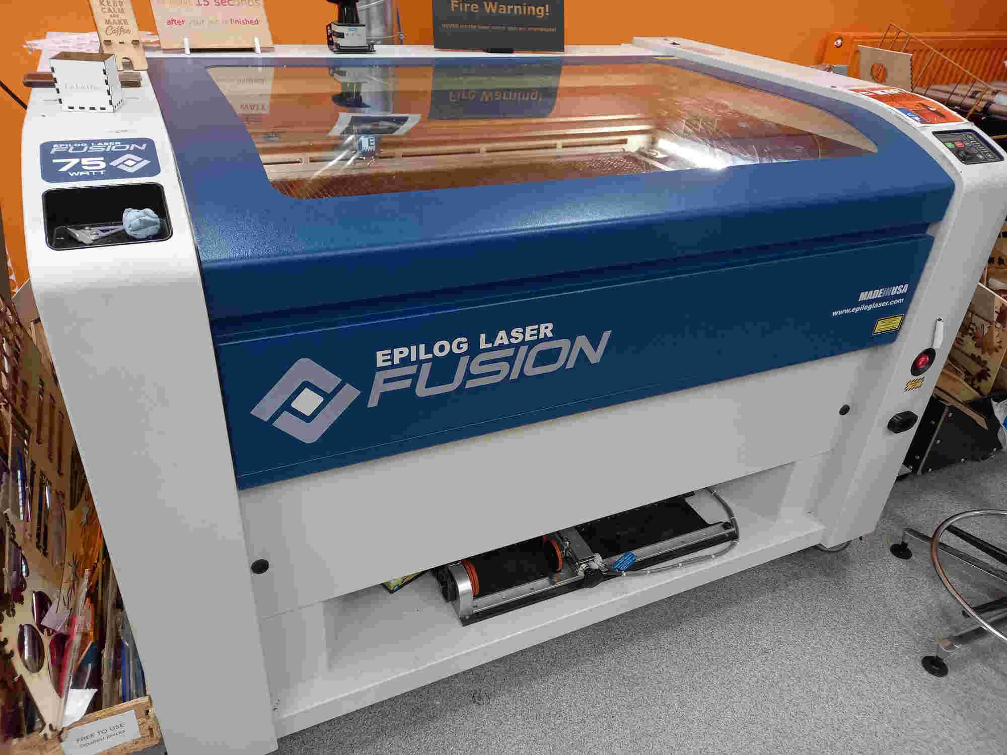
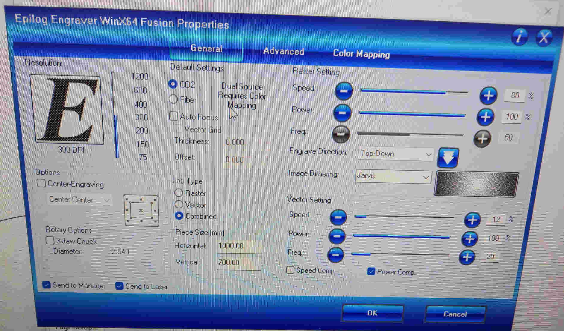
The laser cutter is 75 watt Epilog laser fusion
The settings for the cutter could be loaded from the menu
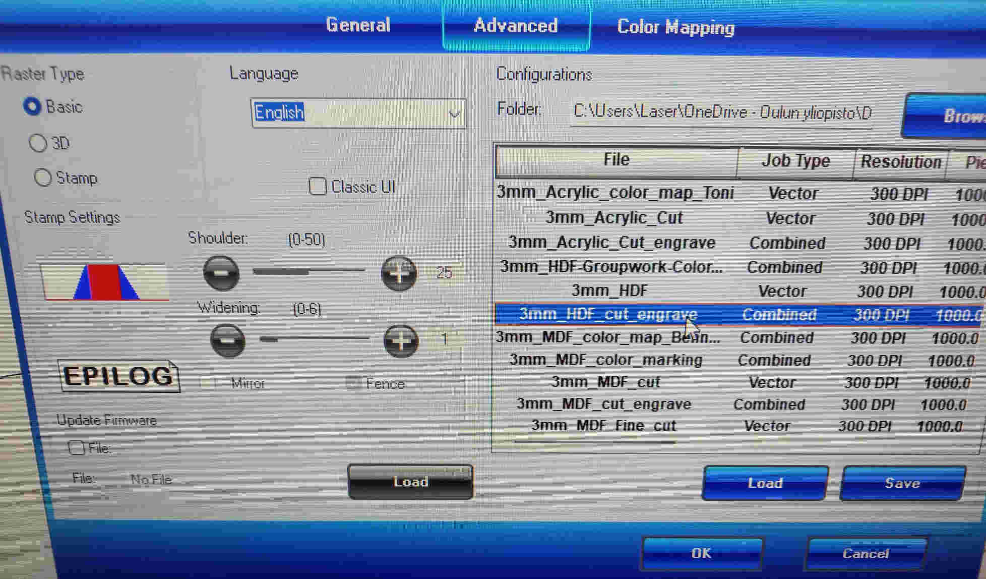
The settings for the cut and engrave 3mm HDF material are shown below
Testing the effect of laser cutting speed and power
We tested the effect of laser cutting speed and power on the cut. We set different values for different squares. The result is shown in the following figure. We used RGB codes to control the speed and power.
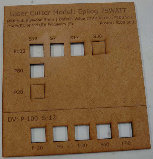 figure on the cut squares
We could see that for fastest cutting speed (S30) the laser was not able to cut through, even if the power was highest (P100). Also, for the lowest power (P20) the laser was not able to cut through, even if the cutting speed was the slowest (S12).
Engravings and contrast of raster images
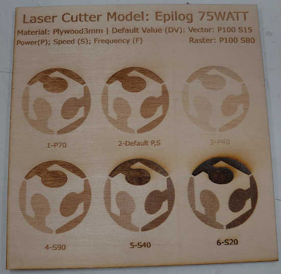 Figure on engravings and contrast.
Raster settings were applied. Default power in the figure is 100, and default speed is 80.
Effect of Dots Per Inch (DPI) setting on laser engraving.
We tried to make engraving with different DPI settings. In a first attempt there was something wrong with the laser focus, and the material seemed to catch quite big flame.
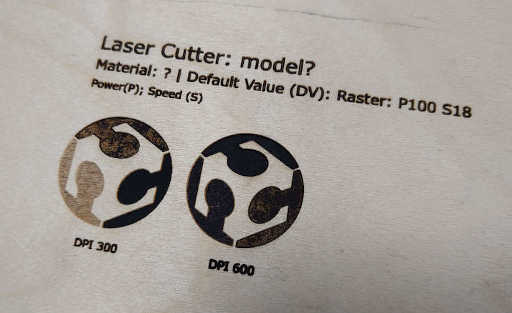 Figure of the first engravings
The material was changed to HDF and the laser was cleaned. After this there was no problem, and we could engrave with different settings. The results are shown in the next figure
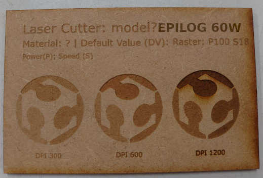 Figure of the second engravings
With more dots per inch, there is more energy deposited per line length, and for this reason the material is burned more with higher DPI setting. The power was set to 100 and the speed was set to 18.
Parametric design
Test cut without considering kerf. We cut several test pieces, ones with chamfer and ones without. When kerf was not taken in to account, the connection was loose, and the pieces did not stick well to each other.
Then we cut pieces, where the kerf was taken in to account. We used the value for kerf based on the measurements we made first in the group work. In these cases the pieces were well attached. It was even difficult to push the pieces together. The reason for this was that the material that we cut was thicker than the one we initially measured.
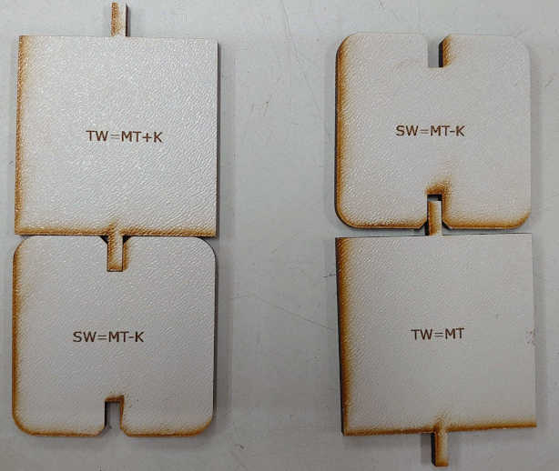 Figure of pieces with and without compensating for kerf
We tested with the pieces, where the correct thickness was used in the design. For one pair, the kerf was not taken in to account in the other part, and it was loose. For the other pair the kerf was correctly taken in to account, and the connection was good.
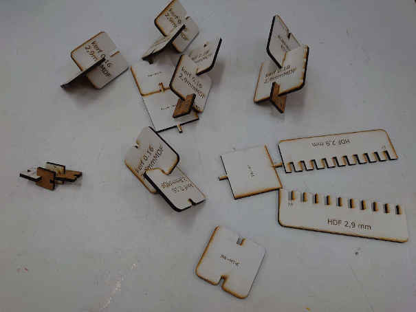 Figure of the ready made parts