Input week. Group 2 Work.
Group members
Group work for week 11
This week we analysed digital and analog sensors with an oscilloscope.
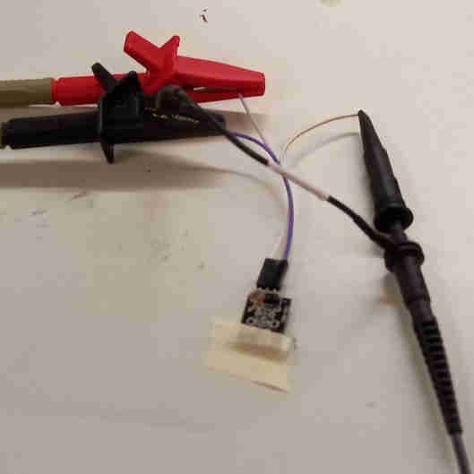
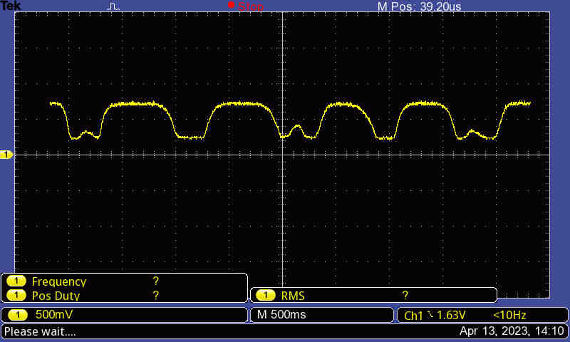
Analog
With the Fab Academy instructor Aleksi, we observed the readings from an analog photoresistor sensor using oscilloscope. The ground and the input voltage wires were inserted to their respective sockets. The voltage difference between the analog output pin and the ground wire were measured.
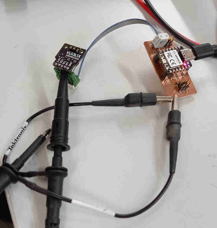
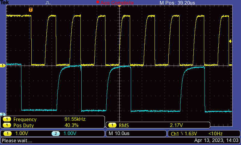
Digital
Using oscilloscope, we also observed the clock and digital signals of the I2C communication transmitted between a VL53L1X time of flight distance sensor and an RP2040. The 5 V input and ground as well as SCL and SDA pins of the RP2040 were connected with breakout board and a cable to the respective sockets of the distance sensor. We probed the clock (SCL) and the digital signal (SDA) pins.