Input Devices. Group 1.
Group members
Week 12 group assignment Input Devices
Weeks assignments
This week assignment was to measure the digital and analog signals from input devices. The test boards and sensors were provided by local instructor.
Test 1: Analog signal from photoresistor LDR
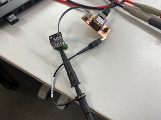
With photoresistor LDR we created circuit where oscilloscope was connected between data pin and ground. We powered the sensor straight from the power source.
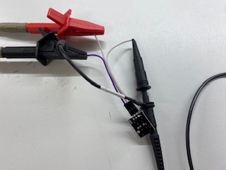
Picture1: Test 1 setup
First measurement was data pin signal when the sensor is freely on the desk.
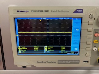
Picture2: First measurement
Next we covered the sensor fully and took picture of the signal from the oscilloscope.
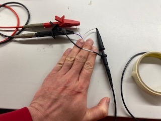
Picture3: Sensor covered
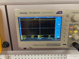
Picture4: Second measurement
Lastly we used the LED light to flash the sensor.
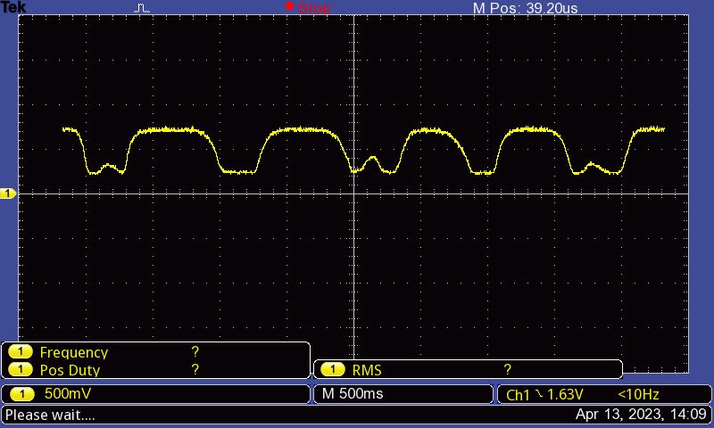
Picture5: Third measurement
Test 2: Digital signal from distance sensor VL53 L1X
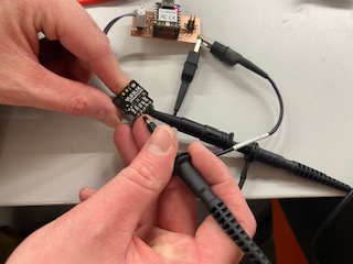
With digital sensor we created circuit where oscilloscope channel 1 was connected between SCL pin and ground. Channel 2 was between SDA and ground.
Picture6: Clocksignal test setup
During local lecture we talked about how the pullup resistors work and how internal and external components differ. In first measurements we looked at the clock signal to get idea where and how pullup resistors effect to the raising edges of the signal.
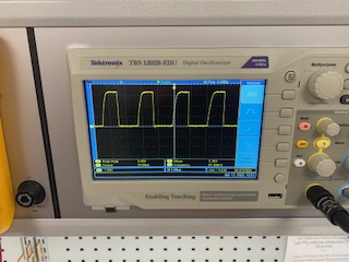
Picture7: Channel 1 clocksignal
In next measurement we added data signal to the second channel.
Picture8: Test 2 setup
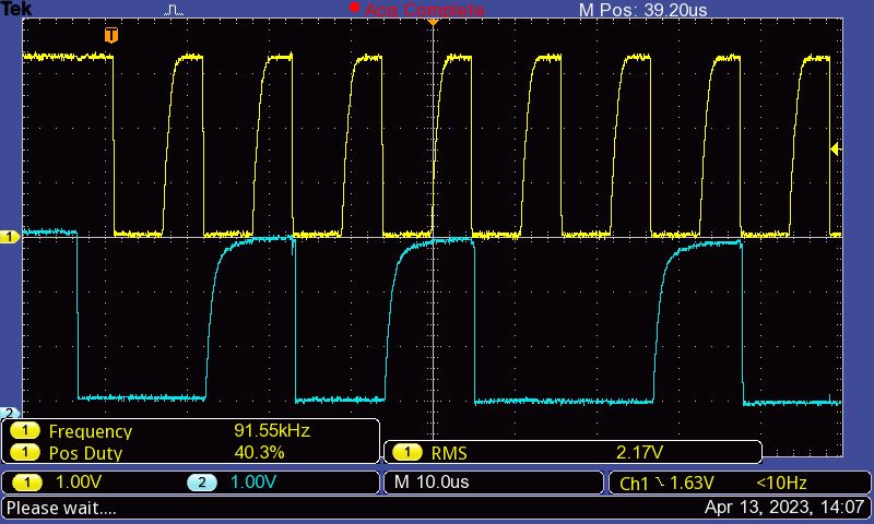
Picture9: Both channels