10. Mechanical Design, Machine Design
Group assignment:
Individual assignment:
Document your individual contribution.
Go to:
Groupwork
Most of the assignment this week is documented in the group work page here on our Fablab Oulu pages. Check out the machines rising!
Our beautiful team consisted of Essi Huusko, Tapio Lappalainen and myself. You can find their individual work on their pages.
Mechanical & Machine design
The start
This week we worked really hard as a group. We did much of the planning, ideation, gathering data, fabrication, assembly and testing together. It was a really fun project, and I'm very fortunate to have such a good team members!
We put our heads together and solved every problem we faced. I don't think finishing this project would've been possible just by myself, or at least not in this tight schedule. So thank you to my team!
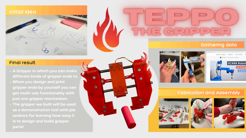
Our group member Tapio had thought about an idea of making a gripper. If it worked out, it could be used in a coming project where job seekers are taught how to make gripper parts by themselves. We all liked the idea that this machine would be in real use.
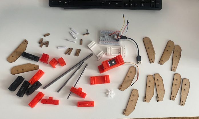
After the initial idea of making a gripper, we did some reasearch on grippers that already exist. We tried a small prototype to get the idea. We got stl files of an existing project, took the files to Inkscape and cut them with laser cutter. We then assembled the prototype. After looking at this linear gripper, we came up with the idea of trying a different kind. We searched and found a nice project page of an Arduino based robot here. We set our aim to build a gripper resembling the one used on Scara. It looked good and suited our purposes.
Individual work
We looked into each of our strenghts. We concluded that to get the project on it's way, Tapio would write code to our machine, and Essi and me would start to fabricate needed parts. We looked into our inspirational project Scara, and understood what would be needed. A couple of the parts we would need to buy (the steel bars), other ones we could fabricate. Between Essi and me we diveded the parts that we would begin with.
I planned to design and make the gripper hands, ends and the links.
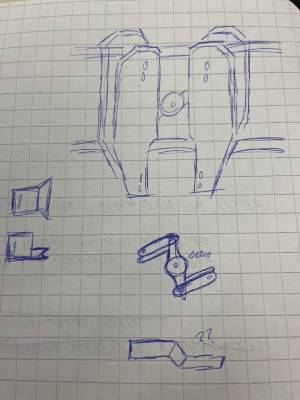
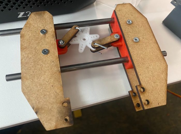
I understood the basic idea. The servo motor comes into the middle to make the movement possible. It is connected to the links which are connected to the hands. The whole system slides on the bars, and you can basically design and attach any kind of gripper ends to attach to the hands.
At the very beginning we weren't sure about the dimensions that we wanted our machine to have. At least I felt that I need to see something put together to be able to understand what would be the ideal final result. But we had to start designing anyway, so we agreed to make the designs with parameters so that the dimensions would be easy to change later if needed.
The links
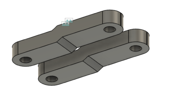
I started designing with the links. We needed 4 links to the system, and they should be able to endure the torque. I saw that in the Scara case two of the links were flat, and two other had a stagger in them. I wasn't sure why, but I chose to do the same and see if it was needed later.
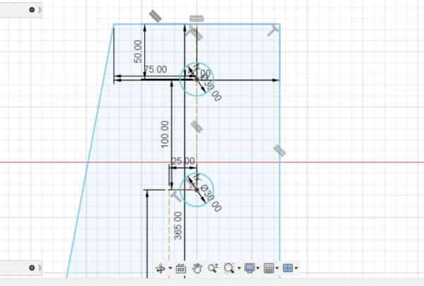
So back again in Fusion. The flat link was easy to make, I just drew a rectangle, added fillets, and drew circles to both ends. Then I extruded. The holes were planned to be 3,2 mm so that it would leave some extra space for M3 screws incase the printing would take away some space.
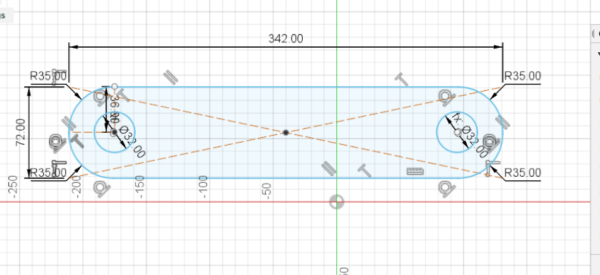
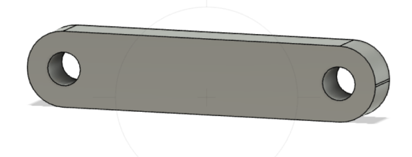
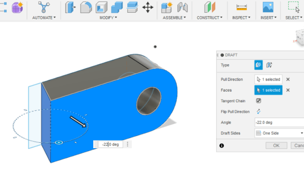
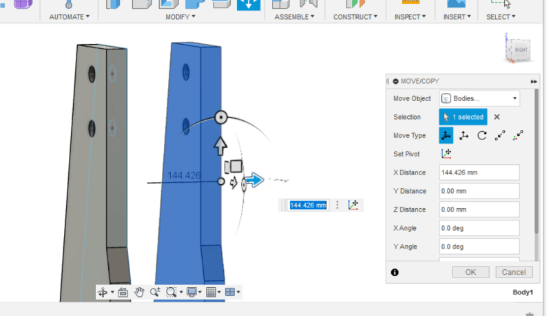
The other link was a lot harder to design. I first made two rectangles with circles in them just like before, but then I had to join them together in this way that it creates like a stepdown in between. So I made one more small rectangle. Then I stared to do drafts to the faces of all the parts that would be joined together. That way I could make the sides oblique and parallel. That worked! When all the angles were right, I just put joints to the bodies and then combined them as one component.
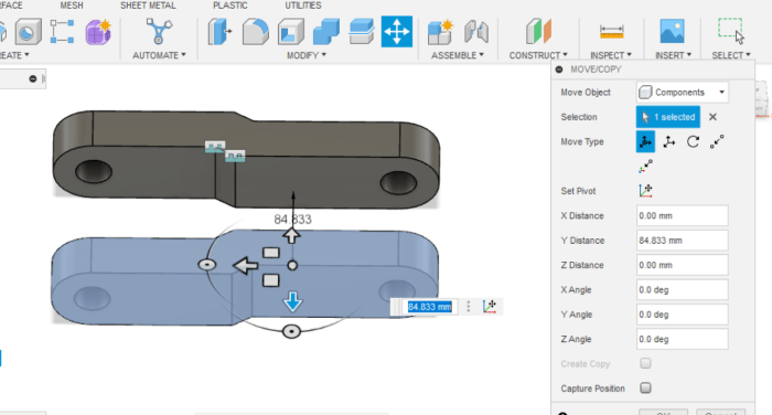
The ready component I just mirrored and aligned, and they were ready!
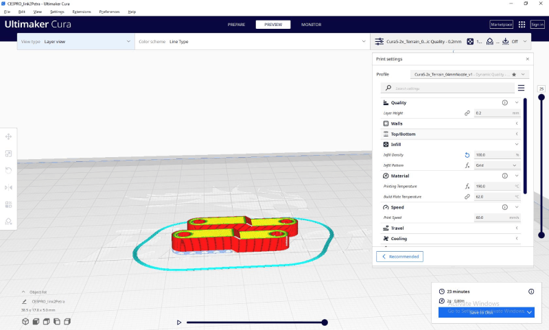
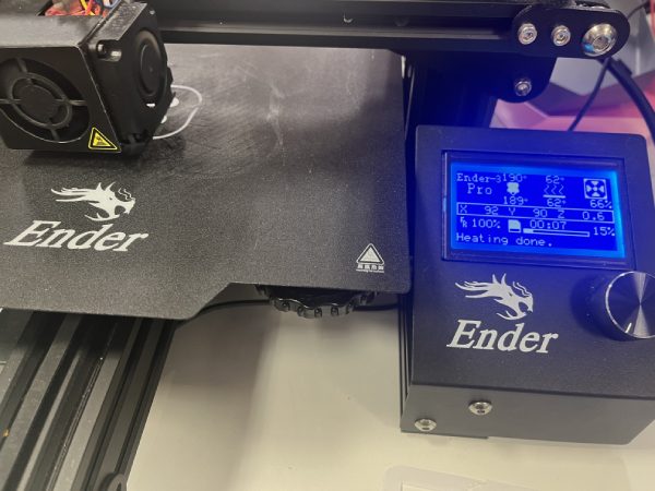
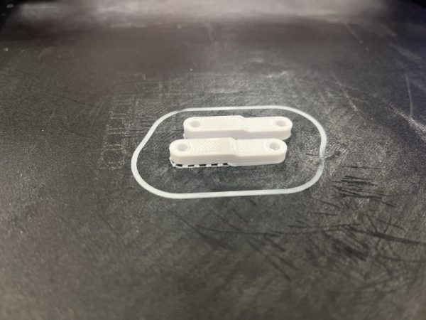
The links I wanted first to 3D print. I thought the first ones are probably for testing since we didn't yet know the final dimensions, but I wanted to see if the printed ones would be strong enough. I used Ultimaker Cura for slicing. For infill I chose 100, since the link has to be strong. Because of the stepdown I also chose some support. Printing temperature was 190 degrees celsius, and the build plate 62. Printing speed was 60 mm/s. The printer was Ender 3 Pro. The printing went just fine, and took about 21 minutes. I also printed the flat links.
The hands
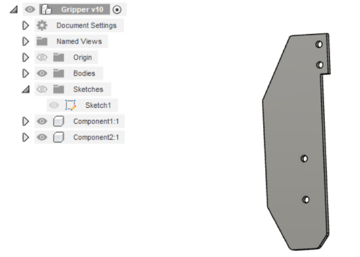
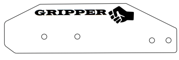
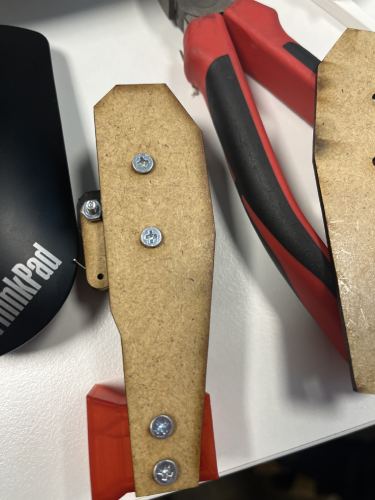
The hands I kept simple. I needed them to have a couple of holes on the upper part for attaching them to the middle part that attaches to the link. I also needed couple of holes on the bottom part for attaching the gripper ends. I thought them to be laser cut rather then printed because I saw no advantages for printing.
In Fusion I sketched them by making lines and circles, and again making the holes about 3 mm for M3 screws.
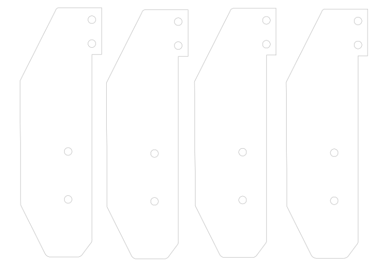
I also mirrored them and made some copies to make all the 4 hands ready here in Fusion.
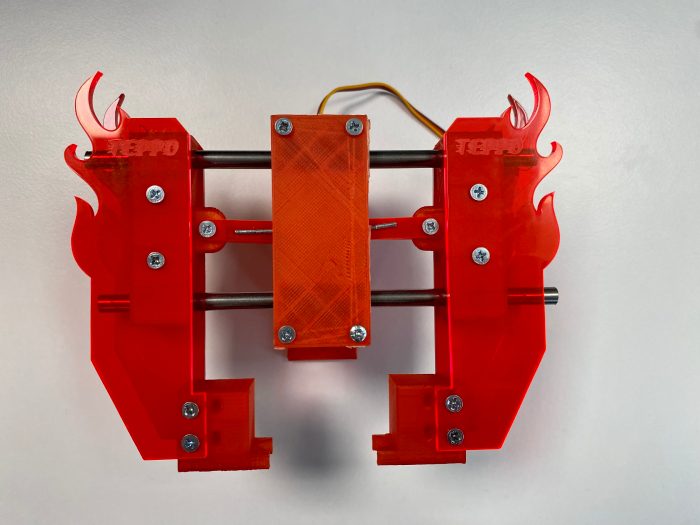
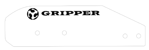
I took them to Inkscape, and added some text and logos. First couple of versions were made out of MDF for testing..but in the end we wanted to do real nice ones from acrylic! The design also changed in the way as we explored with our machine design. In the end the hands needed a small extra piece on the bottom to make full use of the end pieces. When everything else was done to our machine, Essi also added some flames to the sides of the hand pieces. We also named our machine Teppo, so we engraved the name on the acrylic.
The end parts
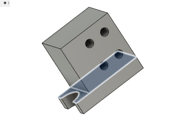
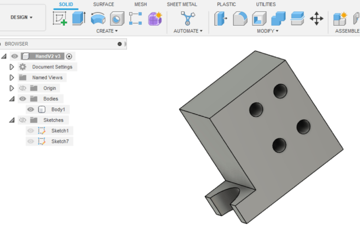
One thing I also did was the end parts. At first I just tried to assimilate the end parts in the Scara -project. We wanted also to have one of our own design for testing, so I made the end parts with an arch. They can grap on to round and oval objects and of course soft objects of any shape.
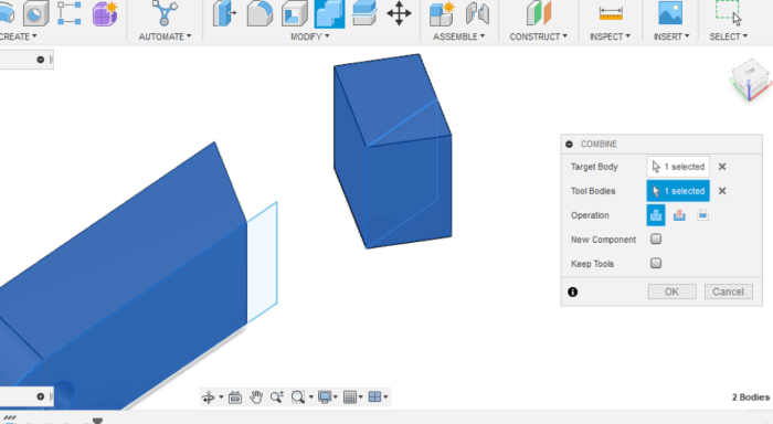
In Fusion I was back to making a simple box, adding holes, and then using draft to make the sides as they are. This part was easy.
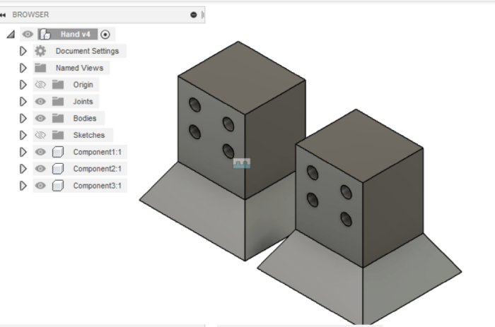
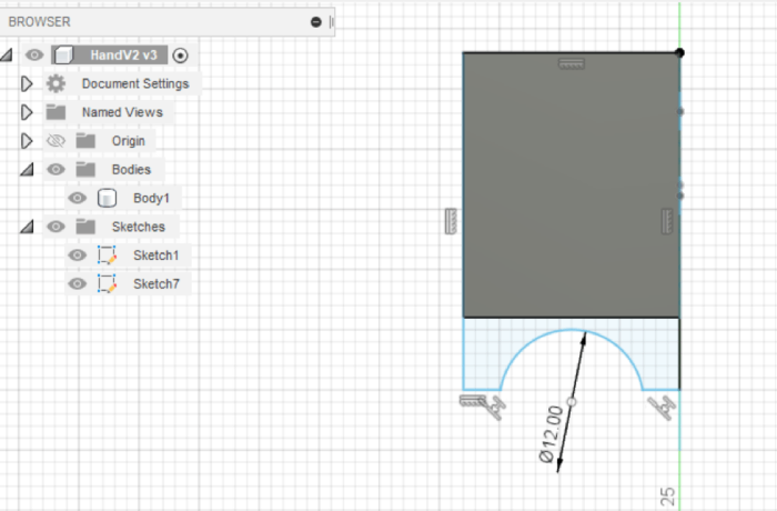
The second ends were a bit trickier. In the sketch I made a rectangle and circles to make the main body part as before. Then after extruding, I added a sketch. I drew lines alongside the bottom part of the first body making another rectangle, and made the second rectangle a bit bigger then the original. Then I drew a circle on top of the new rectangle, and used Modify -> Trim tool to cut off the shape and extruded. For some reason my eyes lied to me and I made the pattern twice to a wrong side of the sketch! Live and learn. Finally it was ready.
The end parts were 3D printed with basic settings and with Sindoh Wox dp201. This was done on one group session we had when we were testing the pieces.
Assembly
We assembled the machine together and did all the tests together. I still wanted to place here some pictures showing parts of the process especially concerning the hands, the links and the end parts.
Here are some pictures about the very first tests. Actually none of these parts as they are here, ended up in the final version.
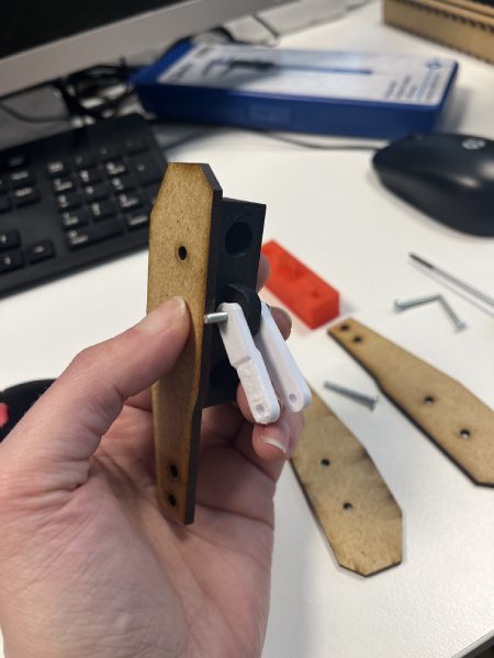
We were assembling these parts to understand the dimensions. When trying to operate the movement, we understood that we have to consider now how wide we wish the movement of the gripper to be.
We also understood that the links were just a bit too long, the degree of motion wasn't as full as we wanted.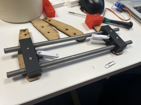
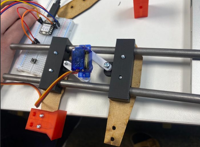
In this point I made new, 10 mm shorter links. I took them to Inkscape and laser cut them from MDF. I also changed the size of the servo end hole to a smaller one, since the holes in servo arm were really small.
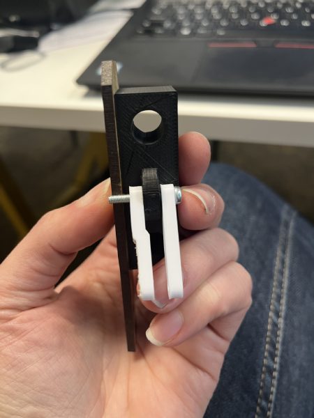
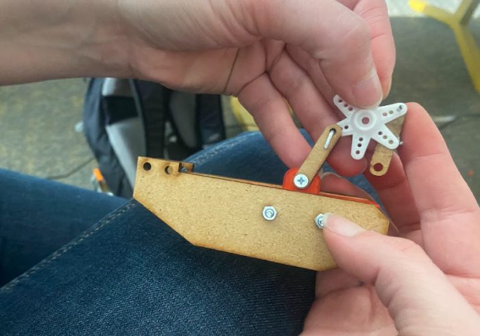
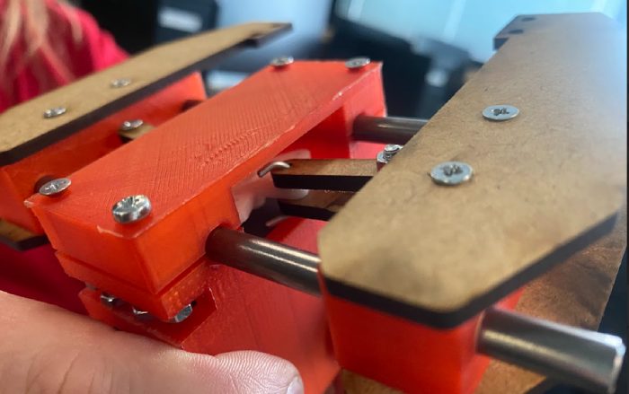
Later on we actually changed the servo to a bigger one. When assembling with that one, we noticed that the links would have to be 6 mm longer to work optimally. So again I cut new ones with new dimensions. In the following picture you can see the right size links, and they are already attached to the final shape of the hands. In the end we also made the links from acrylic for visual reasons.
In the machine building process we did a few tests before we got to the right size and properly working parts..
..But we got there in the end! Here's a couple of photos of the fun and games we had with attaching the links to the servo. As said the holes were really small so we had problems getting them tied up together. We didn't find the very small (1-2mm) bolts/screws from the 2 fablabs or the store. We tried different things and modified some from various things. It was hard since there wasn't much extra space on the system.
It was a fun and learning project, and I'm glad we got to do it! You can see the working machine video in the group pages. For presentation I made the flyer.