My Final Project
My final project is a
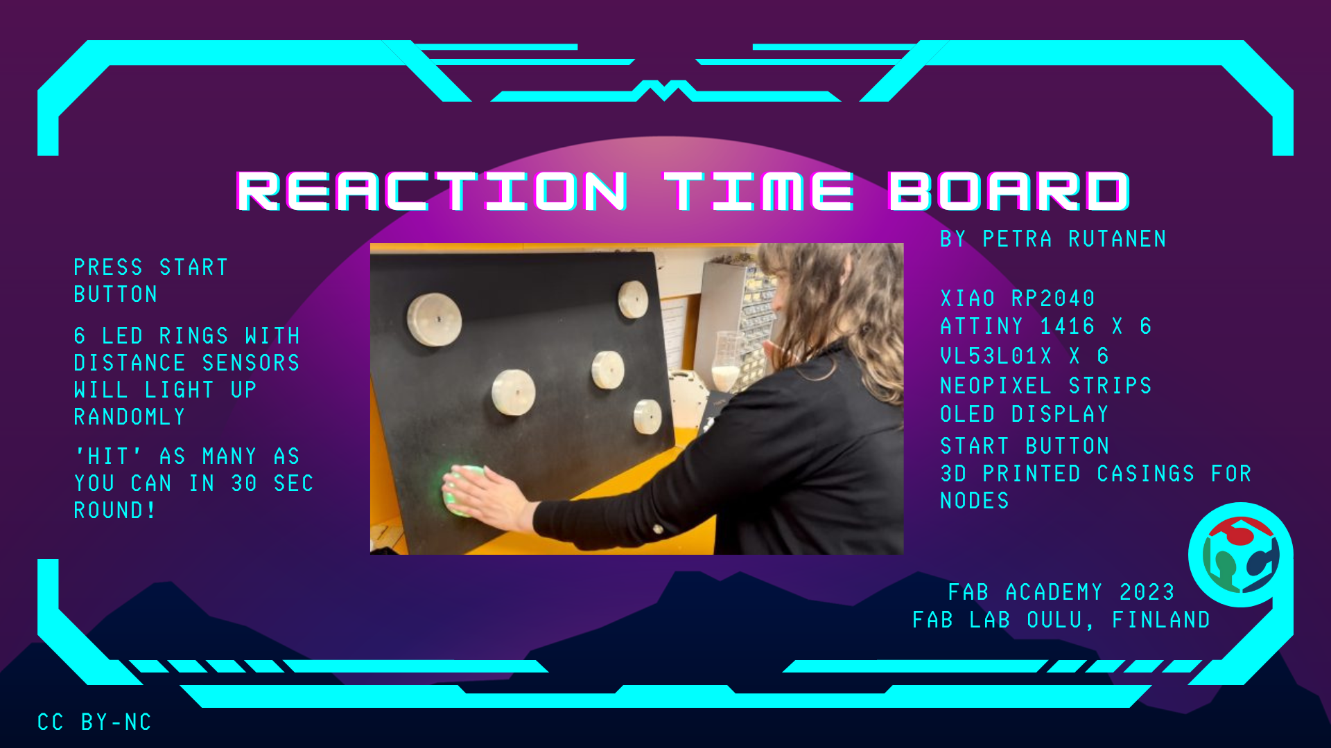
Reaction Time Board
I want to thank Fab Academy, Neil Gershenfeld, and All of Fab Lab Oulu's wonderful instructors for making this project possible. Also many thanks to my fellow students who I had wonderful time with!
Here are the presentation video and slide, I hope you enjoy it!
 >
>
Go to:
Background
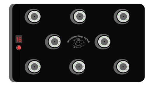
I am into kickboxing, and I train in the best possible gym which is Kickboxing team Oulu (KBT Instagram). I wanted to make a reaction time game for the gym and enjoy it with my fellow kickboxers.
Kickboxing is a full-contact martial and combat art. Kickboxing techniques typically include techniques similar to boxing, kicks and knee strikes and some clinching. It is practised for competitive, fitness and recreational purposes by all ages and genders.
Boxing is a part of the routine, and it's important to train all the skills included in the sport. When I started going deeper into this world, I started to watch some good fights and good fighters. One of them is a Ukrainian professonial boxer Vasiliy Lomachenko. As I learned about him, I noticed in his training videos there were examples of also reaction training.

"19/04/2013 Ukraine Otamans 5-0 Dolce&Gabbana Italia Thunder"
by World Series Boxing is licensed under CC BY-ND 2.0.
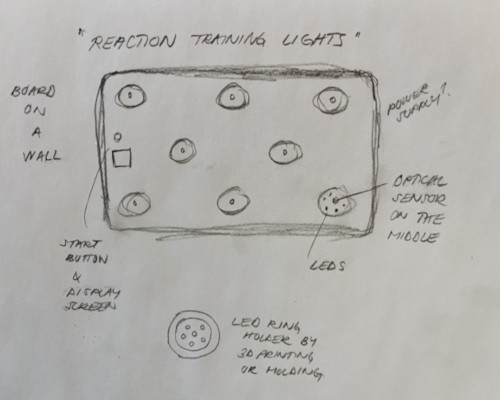
Sketch and Idea
In kickboxing fighters are trained to react quickly to opponent's movements. You need to protect yourself from the incoming attacks by slipping, bob and weave movement, blocking or covering. And of course, do an instant counter attack. This requires a good reaction time and mental focus. As the fighter gets fatigued, it becomes more and more hard as fatigue has a negative effect on your reaction time.
This is why I got interested in designing and manufacturing a reaction time board, that could be used as a fun game at the gym. It could strenghten the body/mind connection, coordination, reaction time, focus and accuracy. Also if the fighters would play it before training, during and after they would themselves see the effect training has on them. Results could be observed thrue time and possible changes seen.
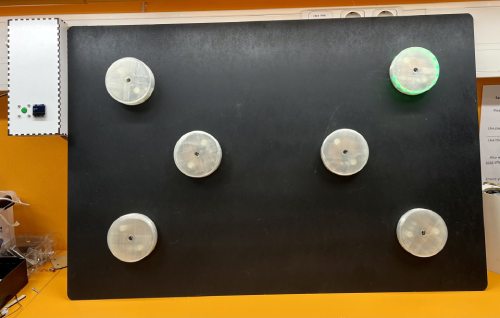
- The idea is to have from 6-8 LED rings over a board that is on the wall.
- When you press the start button, the device fires the LED rings in a random order.
- In each ring there's a distance sensor. When the sensor senses an object with a threshold of 5 cm, the microcontroller sends a message back to main pcb that the 'hit' was successfull and the score is added to the end score.
- After one LED ring deactivates, the next one randomly fires up and so on.
- The time of a round is 30 sec. At the end, the result screen shows your result (how many hits/round.)
Here is a model of the project I made on with Inkscape.
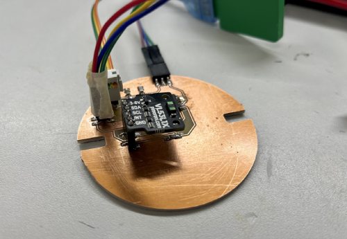
The LED ring
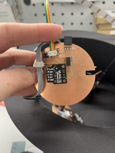
I have 6 LED rings over the board. They act as nodes and each of them has ATtiny1614, which controls lighting up the LED strip and starting the sensor. The node address is the number of the node.
For making the pcb's, I used all the knowledge I had learned previously on Electronics design week and Electronics production week .
The knowledge for using the distance sensor I used my learning from Input devices week (here.)
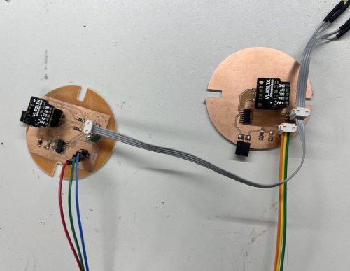
For joining the nodes together I used the knowledge acquired in Networking and communications week (here.)
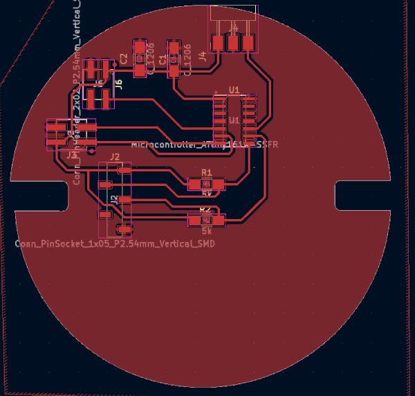
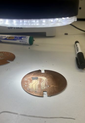
I designed the pcb's in Kicad. The first one was a learning experince. The sensor was not in a good place, one ground was isolated, and my filled zone didn't cover the whole area.
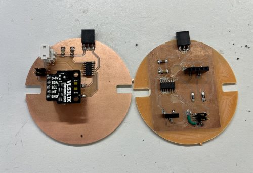
In the final version I changed the position of the sensor to be exactly in the middle of the pcb. I also changed some of the connectors when I first had tried out the functioning. It worked beautifully!
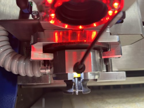
In the making process I learned something new; that is how to adjust the milled line to match my needs. Initially it was too thin. So I turned the big black gearwheel on the machine clockwise to get wider lines.
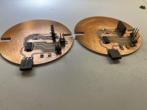
When soldering I found a good order to things. I started always with the microcontroller. Then I added the components from biggest to smallest.
I used flat cable connectors to connect my LED strip and the pins for serial communication. Because they were next to each other, I had to make sure they fit without bending the cables.
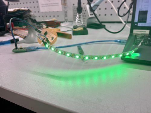
The very first thing was to test if the LED's and the sensor were working. Because I hadn't previously used ATtiny microcontrollers, I also learned about using an UPDI programmer and an FTDI cable for serial communication. My first aim was just to light up the LED strip, and get sensor readings.
With all the testing, in some point I also managed to fry up one microcontroller when I connected the cables wrong! Long working hours might have something to do with that..
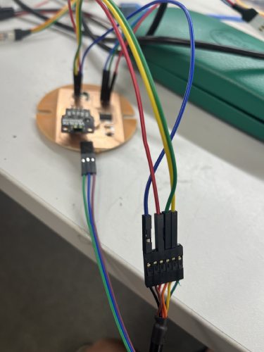
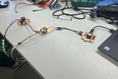
After that I learned about using flat cable and connectors to do the serial communication properly. The wires were really thin inside, and it was a challenge to get them connected to wires! At this point I included my main board, which is the one I made in Electronics production week.
When I started making the nodes, milling one pcb and soldering the components to it took me over 3 hours (the soldering taking most of the time). In a week I progressed in soldering so that I finished two boards in under 30 minutes!
The controls
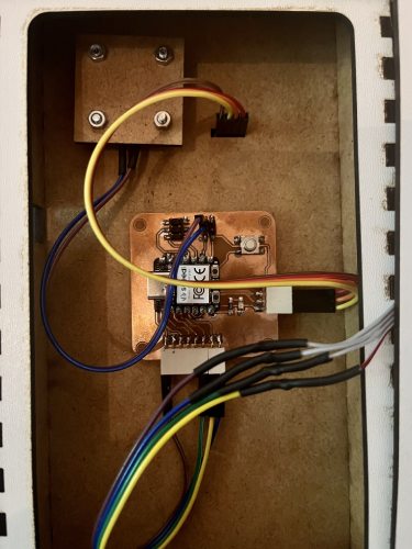
The main pcb, OLED screen and the start button are situated in the controls box. As my main pcb I am using the one I designed in the Elecronics design week here and made in Electronics production week here. The OLED display I learned to use in the Output week here.
The main pcb has RP2040 in it, and I get the power from usb cable that is easily connected to it. In the final project I also used one digital pin for the button, the smaller connector for the OLED (SDA, SCL, Power and Ground), and the bigger connector to the serial line (Tx, Rx, Power and Ground pins).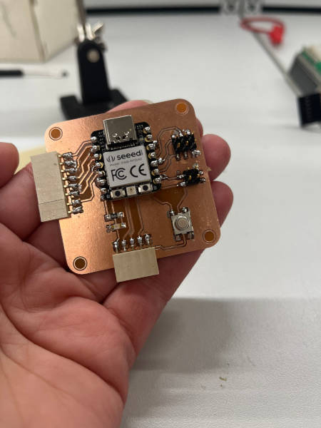
The casing
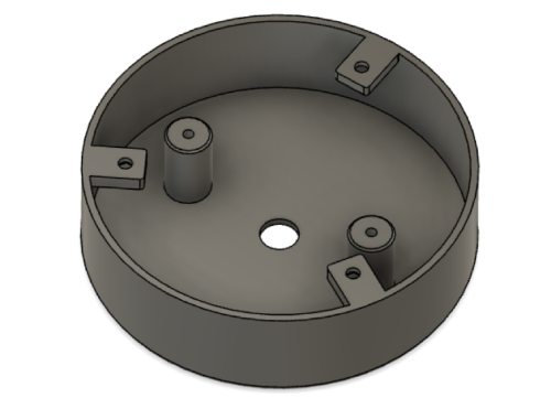
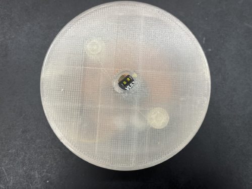
I needed to make something to cover the nodes and let the LED strips shine through nicely. I had a few designs in Fusion on the way, but I ended up with this one. It is made entirely of see through filament. It has 3 mounting fasteners and a hole in the middle for the sensor.
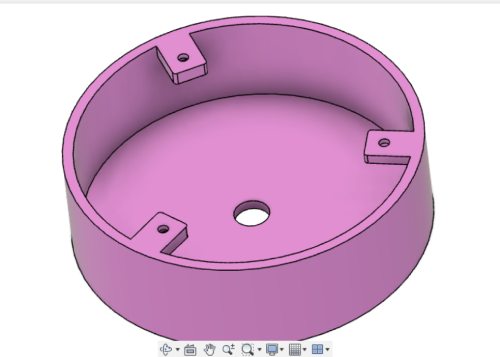
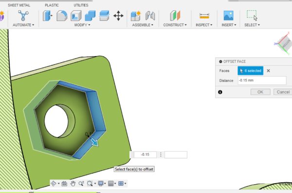
My instructor gave me a couple of beautiful ideas. One was to add a place for a nut in the fastener, so that it is easier to screw in place from the other side of the board. The second idea was to add columns to able to mount the pcb's in place. That way I could adjust the position a bit, and also leave some empty space under the pcb for the wiring.
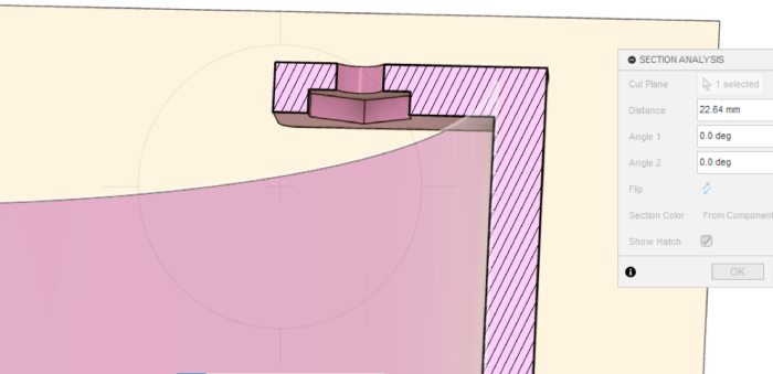
With the nuts and the places for screws I used standard M3 measures. Before printing I was also adviced by my instructor to put on a little offset to the design so that the parts are easier to fit after the printing.
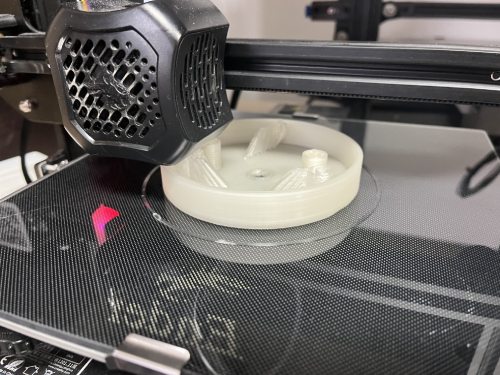
I printed the first test piece. I sliced it with Cura and printed with Ender Pro.
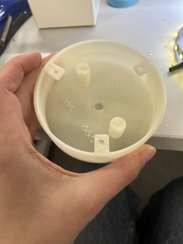
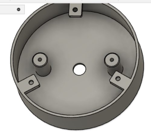
I of course tested the fitting idea then. The pcb went in there really well, and could be adjusted so that the sensor is exactly in the middle of the hole.
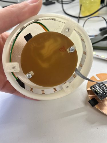
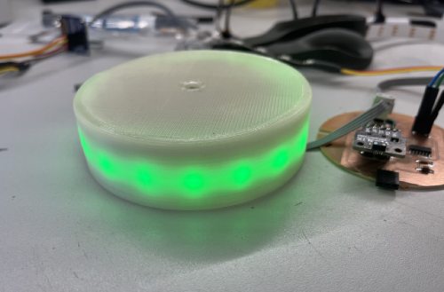
Then it was possible to also test how the LED's look like inside the casing. I think it was pretty good. I still wanted to make small changes; I made the hole in the middle just a couple of mm bigger, and I adjusted the wall thickness to slightly thinner. I think the end result is really good!
The programming
This was by far the hardest part for me in the whole project. With very considerate help from instructors, I got the main functioning of the board working (main pcb sending messages to nodes and firing them up in random turn).
In the video I showed the playing of the game with a certain delay, so that the viewer can get the idea of the working. In the future when I will develop the board, I will make the delay less, so that the player can deactivate the nodes very quickly. In the time frame I didn't get the result working properly, so that is the next thing I will focus on when developing the programming.
Other future plan is also to make different versions of the rules, for example I could use different colors to tell which hand to use. If I get a really good working product, I could also add recording of the results so that the players can compete with who has the record.
The main pcb has RP2040 on it, and all the programming was done with Arduino IDE. The nodes have ATtiny 1614 in them, and it was programmed similarly but with a UPDI programmer. The knowledge to do the programming I gathered thoughout many weeks, for example Embedded programming week, Output week, Input devices week and Networking and communications week. Learning to use the UPDI programmer I looked closely at Adrian Torres's documentation of Adrianino here.
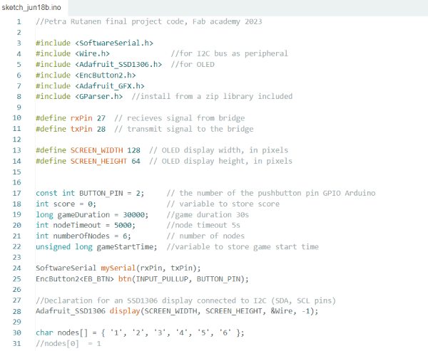
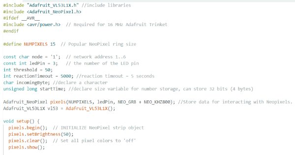
In the mainpcb code, I include the libraries needed. Then I define pins for Tx and Rx, OLED display size, button pin, and for example game duration. Then I tell the software serial to use the defined pins, and for the button to be used as an input pullup.
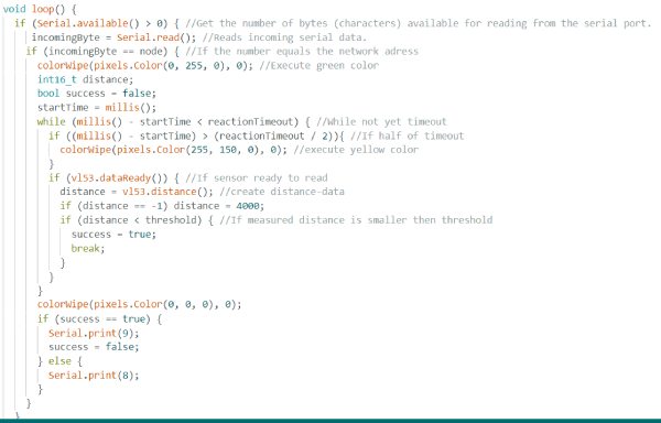
In void loop I tell to check for the button state. Start time is saved to calculate the round. While time is not out, random nodes are fired up.
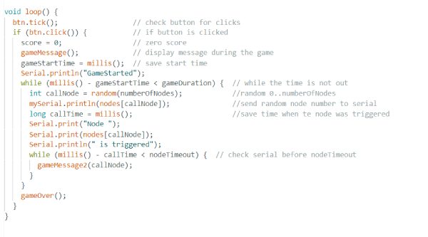
The messages are defined separately, for example the start message and the game over message.
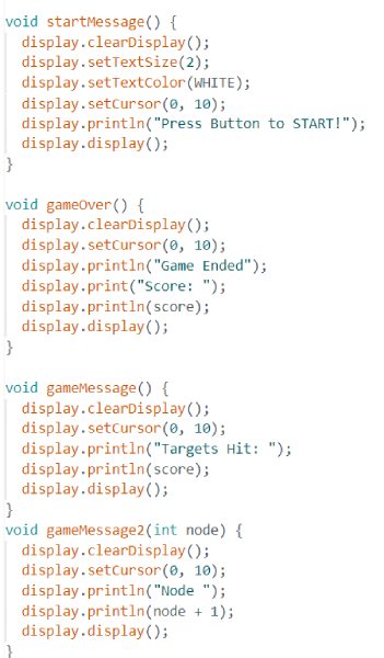
In the node program, libraries are included, LED strip size and number of the pin defined, and the node is given it's network address. There's also reaction timeout, which in the presentation video was set to 2 seconds as a reference.
In void loop, it is said that if the incoming byte from mainpcb matches the node address, light up green color for LEDs and start measuring distance. If the distance is under 4 cm, do a break.
The board and the box
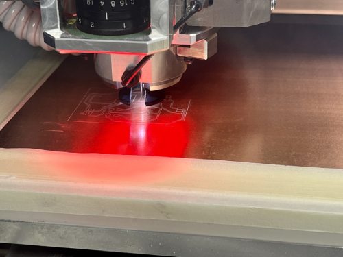
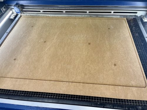
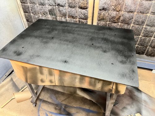
For the board, I just made a simple design of a rectangle in Inkscape and added 6 holes for the through taking of wires to the nodes. I cut it with laser cutter, and painted black with acrylic spray paint.
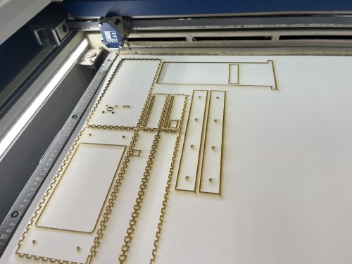
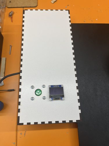
For the controls I made a simple box using boxes.py here as a reference to get the outlines for the box that I then finished in Inkscape. I added holes for the OLED display, button, and for all the wires coming out the back. I also made a closing part, that I can hide the wires. One hole is there also for the power, the usb cord. The design was made in Inkscape and cut with laser cutter.
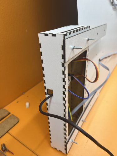
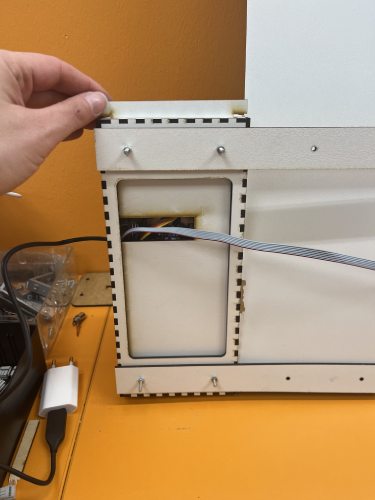
For this project I attached the controls quite lightly. The point now was to present the idea functioning. The main pcb was attached with a drop of glue. Later on when developing the product, the main pcb will be attached to a planned power pcb, which is then put to the place with screws.
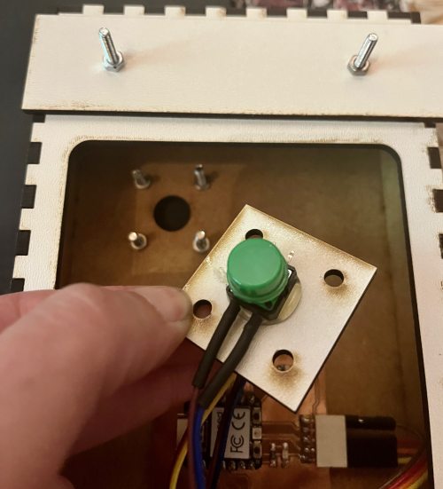
The button needed to be in place securely. So I glued the button to a small plate of HDF, soldered the button pins on correctly, and the plate is then screwed on the box from the front and kept on place with nuts. The button worked quite nicely, it stayed on place and pressing it was easy. In future development, I might use a bigger button just for esthetic reasons.
This combination of the board and the box was good for showing my project. In the future development I will mill a thicker board altoghether. The controls box was actually quite good, so I might use the design in the future too. I will make it from plywood for it to be more durable, and I might change the size a bit.
The license
The license I use for my Final project is Creative Commons: CC BY-NC. This license allows reusers to distribute, remix, adapt, and build upon the material in any medium or format for noncommercial purposes only, and only so long as attribution is given to the creator.
For the software I use The MIT License. It is a permissive free software license originating at the Massachusetts Institute of Technology (MIT). It applies for software and is free of charge and without limitation the rights to use, copy, modify, merge, publish, distribute, sublicense, and/or sell copies of the Software. You can read it fully from here.
Bill of materials
| Material | Evaluated cost, € |
|---|---|
| Material for the board and box HDF | 15,80 (Levypalvelu) |
| Filament, 300g | 750 g/26e = about 10 (Gigantti) |
| Xiao Seeed RP2040 | 9,90 (Partco) |
| ATTINY1614 | 0,88 x 6 = 5,28 (Digikey) |
| LED strip | 23,23/5m = 4,79e/m (eBay) |
| VL53L1X - Light, 3D Time-of-Flight (ToF) Sensor Evaluation Board | 13,83 x 6 = 82,98 (Digikey) |
| OLED display | 0,92 (Alibaba) |
| Button, left over from old projects | 1,80 (SP elektroniikka) |
| FR-1 4"x5" printed circuit board blanks | 33,20/batch, I used 1/3 = 11 e (Bantam tools) |
| Screws, M3 | 4,26 (McMaster-Carr) |
| Female 1 row horizontal headers | 0,86 x 6 = 3,9 (Digikey) |
| Male 2 row vertical connective headers | 0,37 x 12 = 4,44 (Digikey) |
| Capacitor 10 nf | 0,05 x 12 (Digikey) |
| Resistors 4,99k | 0,01 x 12 = 0,12 (Digikey) |
| Pack of connectors for flat cable | 5,31 (eBay) |
| Black acrylic paint | 10,95 (K-rauta) |
| In total | Evaluated cost, 172,27 € |