14. Networking and communications
Group assignment:
Individual assignment:
Design, build, and connect wired or wireless node(s) with network or bus addresses
Go to:
Groupwork
The group assignment this week is documented in the group work page here on our Fablab Oulu pages. Check out our results!
In the assignment we used the SoftwareSerial library. I read about in one tutorial here. It says: "The SoftwareSerial library was developed to ensure that any pins of Arduino can exchange Serial data with other peripherals using software. Arduino Uno, for example, has only one HardwareSerial port (pins 0 and 1), which is connected to the USB via the USB to UART conversion chip. Thus, if you have any other peripheral that requires serial communication, in the absence of SoftwareSerial, you’d have to do away with USB Serial communication."
Our steps were (to remind myself):
Defining the Software Serial you first include the library:
#include SoftwareSerial.h.
Then you need to create a SoftwareSerial object using two arguments − the RX pin and the TX pin. Multiple SoftwareSerial objects may be created, but only one can be active at a given moment. We used the digital pins D2 and D3.
#define txPin D3 (transmit signal to the bridge)
mySerial.available() gets the number of bytes (characters) available for reading from a software serial port. This is data that has already arrived and stored in the serial receive buffer.
With mySerial.begin(speed) you set the speed (baud rate) for the serial communication.
mySerial.write(val) prints data to the transmit pin of the SoftwareSerial object as raw bytes.
We used our previously designed boards with RP2040. Two things to remember: When combining projects in serial, the RX and TX pins must be crossed with jumper wires. And the code needs to be loaded into both projects. After compiling the codes, we were able to send and receive messages through Serial Monitor!
Connecting nodes
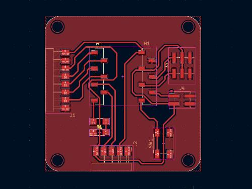
So now to individual assignement: Design, build, and connect wired or wireless node(s) with network or bus addresses. Since time was again of the essence, we agreed with my fellow student Essi that we could use eachothers boards for this assignment. We have the same board, that we designed in week 6. and produced in week 8.
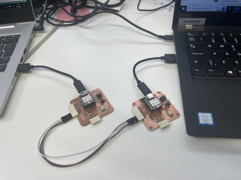
So the idea was to use these projects; one as a host and one as a node and connect them with wires. Setting up was as in the group work; I connected TX and RX pins crossed, and also power and ground.
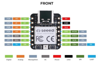
I checked up my pcb pads and decided to use the 8-pin connector and digital pins D2 and D3. I also double checked from the RP2040 pinout that my connections are as they should be.
The setup picture is taken when I got the boards connected and working properly.
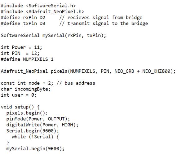
Then to the code. As I still am very new to programming, I had to rely on the example codes given to us in our labs wiki. There was one code for the host, and one for the node. Our instructor was so kind that he modified some code for us who had the RP2040.
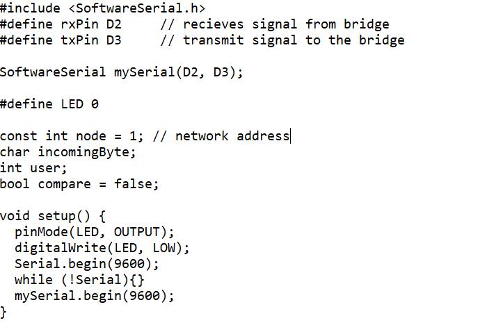
I used my own board as the host. As it has the RGB LED in it, that was also to be used. Therefore; in the code the libraries were included for the SoftwareSerial and and the Neopixel. Then RX pin was defined as D2 (receives the signal) and TX to D3 (transmits the signal). Then I created the SoftwareSerial objects with SoftwareSerial mySerial(D2, D3).
The network address of the host was defined as follows:
const int node = 1; (the host)
const int node = 2; (the node 2)
Then the variable 'incomingByte' was created and used char as the data type to store the value:
char incomingByte;
The code used a variable 'user' with integers that are primary data-type for number storage:
int user;
On void loop() the code says; if the port is ready, get the number of bytes (characters) available for reading from the serial port, and read the incoming serial data.
With mySerial.write it writes binary data to the serial port. This data is sent as a byte or series of bytes.
Later on in the code it is specified that if the user calls for specific node, print node number and light up the LED for 400 ms.
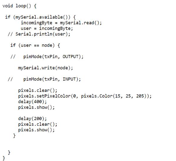
I loaded the host code to my board, and the code for node 2 to the other board. When the compiling was done, I tried to write to Serial Monitor. I wrote '1', and my board flashed it's RGB LED and it replied with 'Node 1' in the serial monitor. When I wrote '2', nothing happened. I tried to look at the code. As I knew my instructor had successfully tried it, I thought that maybe the problem is in my pin setup or in my board (soldering problems?). I tried to use different pins also, and checked the board closely, but nothing helped.
In this point I asked help from my instructor. He said one thing I didn't take into account; do the boards have enough power? At this point the power pins were connected with jumper wire. I knew that had to be the problem, so next I attached the other board with USB to another power source.
Now when I tried...first nothing! But after a few moments, it started to work. I don't actually know why it took some time. I didn't change anything, but it just started working (and kept on working).
So now the node 2 was answering also, and lighting the LED. Happiness!
Here is a video of host and node answering and blinking the RGB LED.
As we were using eachothers boards for the assignment, I was talking with Essi about trying to use also the LEDs we had added on to the boards earlier on. We joined our forces here. One of us was trying to get the code for Node 2 working, and the other was editing the code for the host. It was a trial and error work.
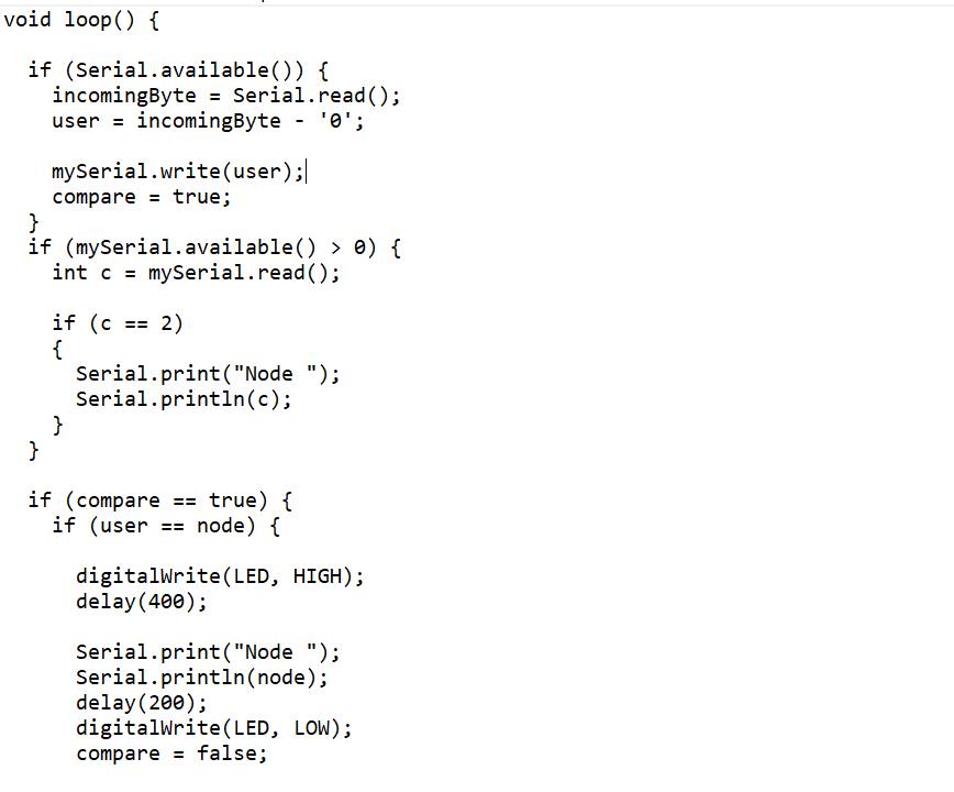
We knew we didn't now need the Neopixel library and such things. Instead we defined our LED with #define LED 0, using the pin 0 that we had our LED on. Then on void setup, we used pinMode to configure LED as an output, and assign the LED as LOW in the beginning.(this we didn't do at first, and the LED was on right away.) We used:
pinMode(LED, OUTPUT) and digitalWrite(LED, LOW).
On void loop we set the following:
If the node is called, (in addition to writing the node number):
digitalWrite(LED, HIGH); // turn on the LED
delay(400); //with delay of 400 ms
digitalWrite(LED, LOW); // turn off LED
This worked! On the video you can see that our boards have different LEDs; the other one has clear and the other one has green.
The host and node answering but with the LEDs of the board.