12. Input devices
Group assignment:
Individual assignment:
Measure something: add a sensor to a microcontroller board that you have designed and read it.
Go to:
Groupwork
The group assignment this week is documented in the group work page here on our Fablab Oulu pages. Check out our results!
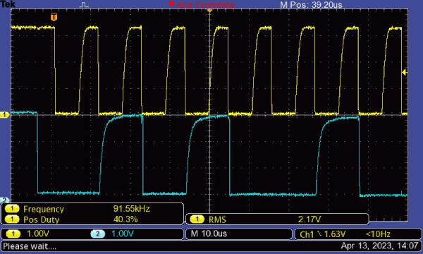
We looked into analog signal from photoresistor LDR, and saw the changes in data pin signal when the LDR was covered. When probing the digital signal from distance sensor VL53L1X, the first channel was set to the clock signal and the second to data pin. In these we clearly saw the slope of the rising signal, which was effected by the pull-up resistor. In this case the pull-up resistor was external, and with that it was possible to effect the slope. Often the internal pull-up resistors are bigger, and when you use external resistors that are smaller it is possible to read data faster and better.
In the local class, one really important thing for me was the use of oscilloscope. I hadn't before had so good directions about the using of it. Our instructor showed us how to get the signal viewed properly (you can try Autoset, and then tweek the knobs for channel scaling if this doesn't do it), how to stop/run it, the measurements you can take etc. Now the oscilloscope doesn't anymore seem like a device from outer space!
The VL53L1X sensor
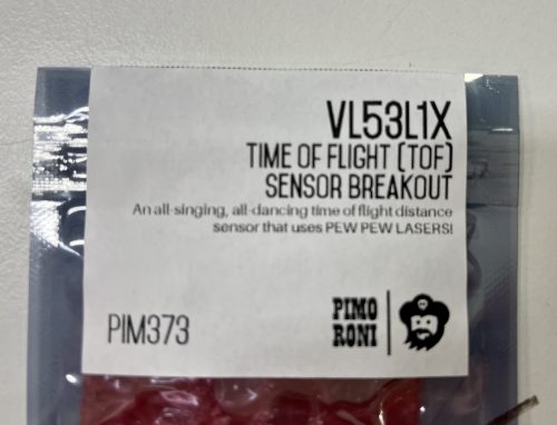
For this week I chose to test a distance sensor VL53L1X, which I could be using in my final project. In the final project, the reaction time game, my aim is to have LED rings that light up and the palyer has to shut them down by moving his hands over the ring. Then the next ring lights up and so on. In the end, after for example 30 seconds, you get the result of how many rings you got to shut down. I thought this distance sensor could be the one sensing the hand over the ring.
First I read some things about the VL53L1X from the datasheet here.
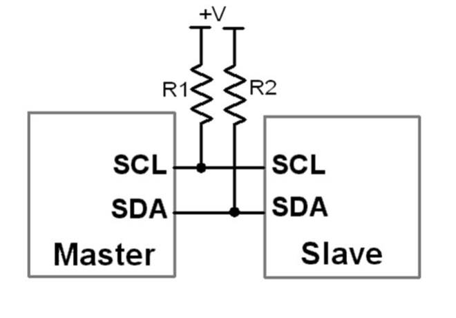
It is a long distance ranging Time-of-Flight sensor that has up to 400 cm distance measurement and up to 50 Hz ranging frequency. Time-of-flight means how long the light has taken to bounce back to the sensor. It has I2C control interface,and it uses two signals: the serial data line (SDA) and serial clock line (SCL). Both SDA and SCL lines are connected to a positive supply voltage using pull up resistors located on the host. Recommended operating voltage of 2.6-3.5 V.
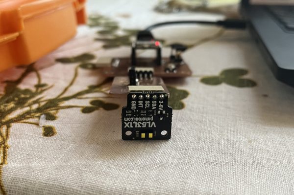
There is a power pin 3-5 V, SDA, SCL, INT and Ground pins.

The board
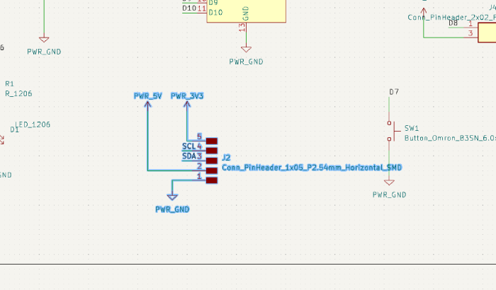
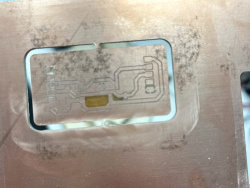
I was hoping that the sensor would fit right in to my excisting board I made in the Electronics production week. It didn't..Here you can see the connective pin header from the original board that has the SDA and SCL in it.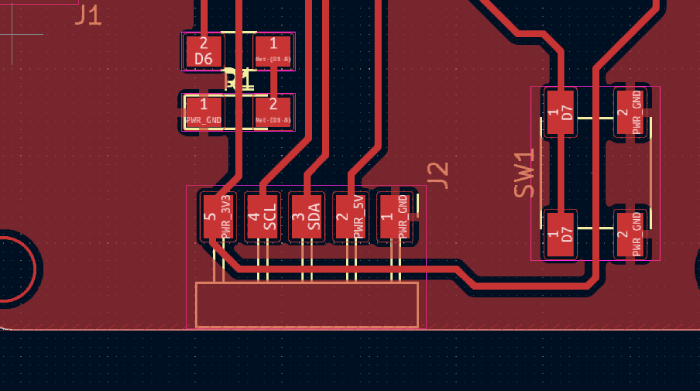
So the order was wrong considering my sensor. I understood I had to make a daughterboard to fit in the sensor. I thought this would be a gigantic effort in a short time, because I surely don't yet master KiCad and the PCB making process. Very fortunately, my instructor had time to help me. It would have not been possible without that help in this time.
KiCad
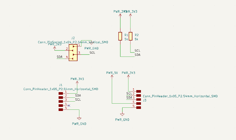
Off I went to KiCad with trembling hands. In schematic I started to bring in parts. I needed:
I found this nice picture of pull-up connections on I2C from Arduino.cc.
One new thing I learned was that I can take a part from an old schematic and copy-paste it to the new one. That I did with the 1x5 pin header.
I mirrored and rotated some parts to plan for a sensible board. I also named the pins and then did the electrical rules check. Everything seemed to be ok, so I opened the PCB editor.
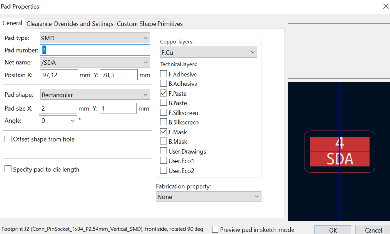
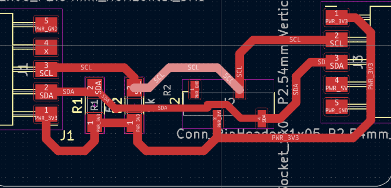
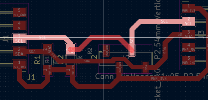
In PCB editor I pulled around the parts to make a sensible unit. Then I was off to route the tracks. I clicked the smallest pad, which was one of the pads in the pin socket and pressed e. In the opened pad properties there was a pad size y of 1 mm. Therefore I set the track size to 1 mm width which was the safest. Then I had to select the 1 mm from the dropdown list of track widths.
While routing, it was again very hard to get all the parts in a way that they are not too close to each other, and ground plane covering all that needs to be covered. But while doing this I got some really good advice on short cut keys. For example when I choose a piece of a trace, I can press 'u' and it chooses the whole trace. If I press 'd', I can move around the trace without the ends moving. These were very useful.
When everything looked alright, after a lot of tweaking, I made the filled zone (ground plane). I drew a rectangle over the parts, and pressed Add a filled zone. At first there were some missed areas. I was adviced to adjust the clearance from copper zone properties. I selected the filled zone, pressed 'e', and searched for the clearance. When I got it to a smaller value, the ground fill covered everything. It seemed that my grounds were now alright.
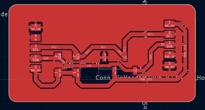
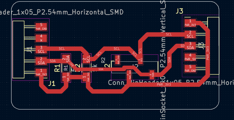
This is the finished pcb without the filled zones showing. I saved the gerber files and went off to making the board.
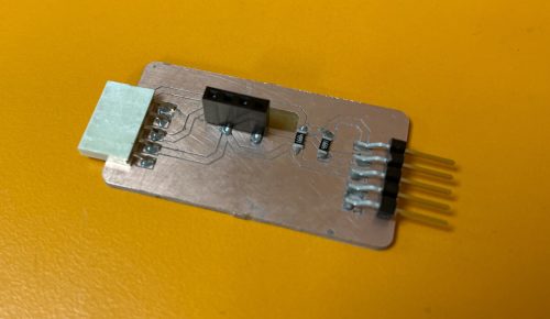
The board and assembly
I used again the LPKF precise milling machine. I did all the steps as I did before described at the Electronics production week. This board was really fast to make as it was small. This is the outcome!
Then there was the scary part of getting the components on the board. I thought it might be wise to do it all with soldering paste and the oven. I didn't remember how small all the parts are..and how hard it is to get the right amount of paste to it. I tried it anyway. It was quite frustrating. When I got a couple of components on their place and was adding paste on other pads, I accidentally moved the ones I already got there. I should have a micro robotic hand for microelectronics! I felt my fingers were giants. Well, to oven it still went. I preheated the oven, and then remember that the rails for the board should've been set correctly before that. My instructor helped me with the hot rails, and fortunately did not burn his hands. I think the personnel here should have some kind of bonuses for hazardous work.
After the oven I noticed that the pin socket had left it's place. Also I had put way too little paste to every part, they were stuck but there clearly wasn't enough solder. When I used the oven first time it was quite the opposite..maybe next time I get it right and put in just the right amount.
Off I went to soldering station. First I tried to do some damage control to the pads of the pin socket. I removed some of the solder that had spread all over. In this point I had to be reminder to put the exhaust fan on..Then I started to solder the component there. First I melted some solder to one pad, and then pressed the first socket leg over it and started to melt the solder. It sunk in there quite nicely. Then I just added some solder to it. Now it was easier to solder all the other legs. This was a good tip from my instructor!
I had to add a lot of solder to all the joints. I think in the end it started to work out really nice. I feel I finally got the idea and know how to get the solder in to the right places, without it spreading. I also had to remove some excess solder from traces, there were some tiny bubbles that were a left over from the oven. Phew!
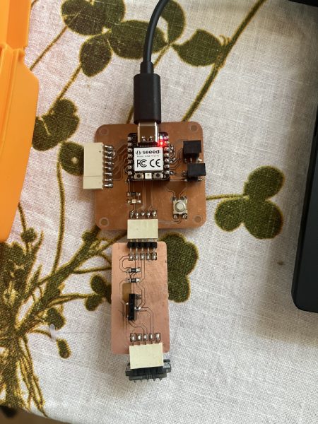
Testing the sensor
First step was to check if the board actually works after all the soldering mess. I attached the daughterboard to the original board, and then attached the sensor to it.
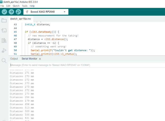
I opened Arduino and loaded the example code I had from my instructor in our labs wiki pages. And it worked!
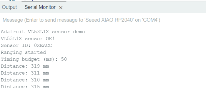
Here is the starting text defined in the code, from the serial monitor.
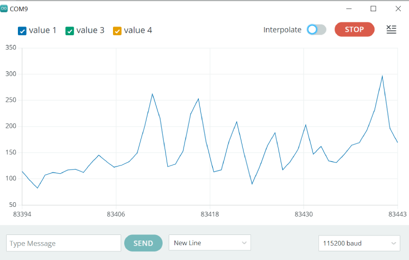
I also looked at the serial plotter for the first time. It shows data that is sent from the board. It functions the same way that the serial monitor does, but is a greater visual tool.
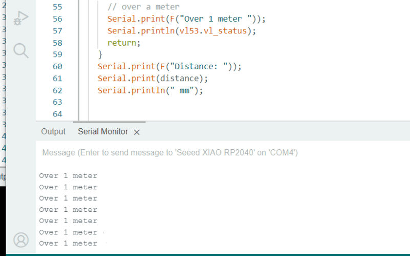
Here is the message if the distance is too long to measure with the sensor (datasheet says over 400 cm).
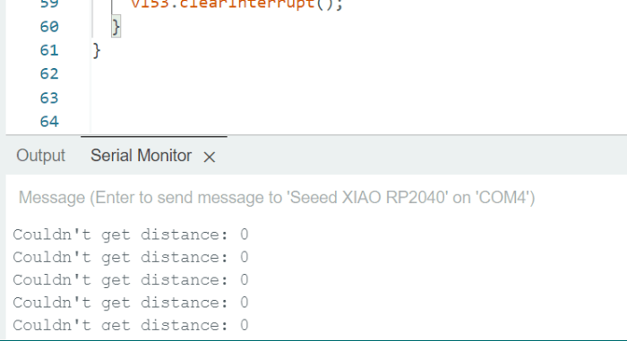
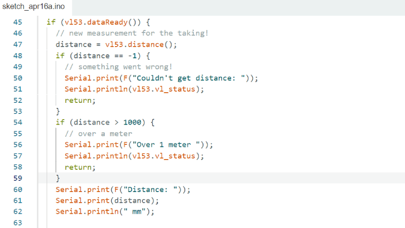
I modified the example code slighlty, by adding a conditional message. If the distance measured is over 1000 cm, write 'Over a meter'.
I also set the board and the sensor on the table in a way that they cannot move. Then I put different objects on the exact same spot and looked if the measured distances are the same. There were some slight differences, the measurements had variations between +- 10 mm. I had some reflective and transparent surfaces, and normal surfaces but with different materials. I concluded that there are some sensor charasteristics here, but also I believe non of my measured objects were 100% flat on their surfaces so a big part of this can come from that. This I have to look into more from the literature.
Considering my final project, I will continue with this sensor and find more about it.One thing I'll do next is to try and get a reading from the sensor to OLED display. I didn't yet have time to do it this week. But there's one thing I did find about the sensor that is quite important.
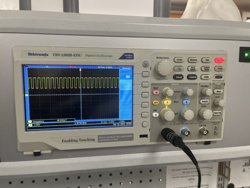
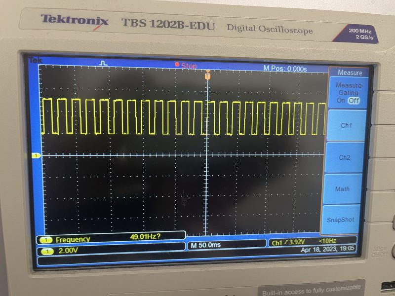
With instructors, I made a digital pin to change it's state when measuring was done and probed that with oscilloscope. When the sensor was giving out the readings, I looked at the signal from the oscilloscope. I noticed that the frequency was showing about 10 Hz.
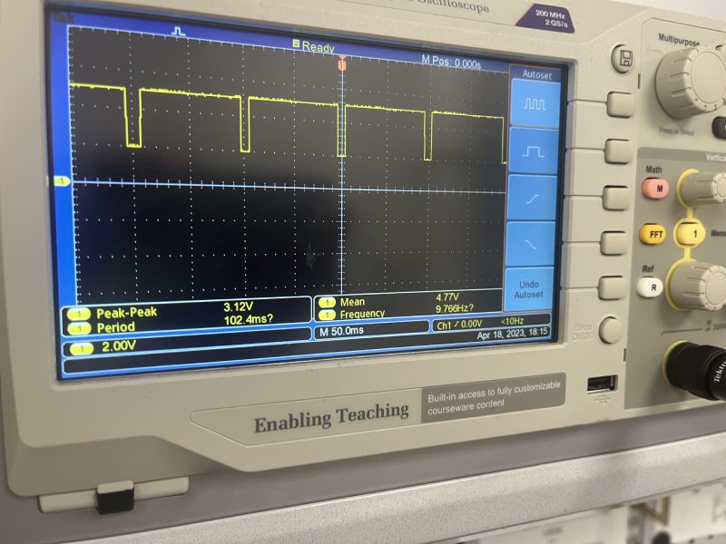
I remembered that the datasheet said that the sensor can go at least up to 50Hz. I didn't understand if there was something wrong, or why didn't I get the 50 Hz? I asked for help from two of the instructors who were present. We all searched for literature, and then my instructor for the week found out how to do it.
In this user manual everything is well explained.
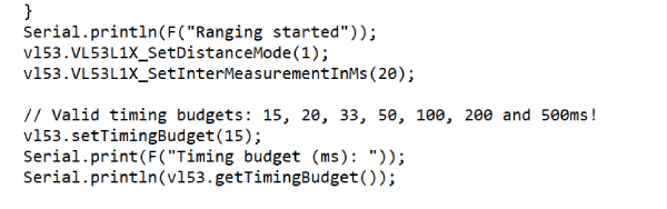
SetDistanceMode programs the sensors distance mode. Two distance modes are available: Short and Long. In the manual it says Short mode has better ambient light immunity but the max distance measured is limited to 1.3 m. That is fine in my case.
We also needed it to function fast. The sensor can work with Long distance mode while it is performing fast ranging. However, the 10 ms of timing budget available is not long enough to get an accurate and consistent measurement. To get consistent ranging data, it is a must to set the distance mode to “Short”. Therefore we chose the short mode (1).
We also tried different Timing budgets. The timing budget is the time required for the device to make one distance measurement. Increasing the TB improves the measurement reliability but also increases power consumption. Therefore there is a trade-off between measurement accuracy and power consumption. In the VL53L1X the TB values available are [15, 20, 33, 50, 100, 200, 500 ms]. We set it here to 15 ms. The smallest timing budgets are available only in Short ranging mode.
Then the Intermeasurement mode function programs the time between two consecutive measurements in ms. The IMP must be greater than or equal to the timing budget. The inter-measurement period we set was 20 ms.
And after all this we got about 50 Hz!
Many thanks to my instructors Aleksi and Gleb! Even if I would've found the manual by myself, it would've took me ages to write the code appropriately. I am very happy I learned these new things, and it is important to me when moving on with the final project. I also got a nice tip, that I might only need to set a threshold for the sensor to measure, to be able to easily make some functions in the code on the reaction time game.