11. Input devices
During group work, we measured the input from both analog sensor and a digital sensor: we measured the voltage difference between the photoresistor and ground, which was affected by the amount of light that was coming to the sensor. The digital sensor was VL53L1X time of flight distance sensor, and we measured it’s communication with RP2040 using I2C. I2C uses two lines to achieve the communication: one line is for the clock signal (SCL) and the other line is for the data (SDA). Also power and ground are connected. We measured the signals of the SCL and SDA by using oscilloscope. The oscilloscope readings showed the clock signal and the data which was being transmitted.
Measuring the photoresistor connected to my own board
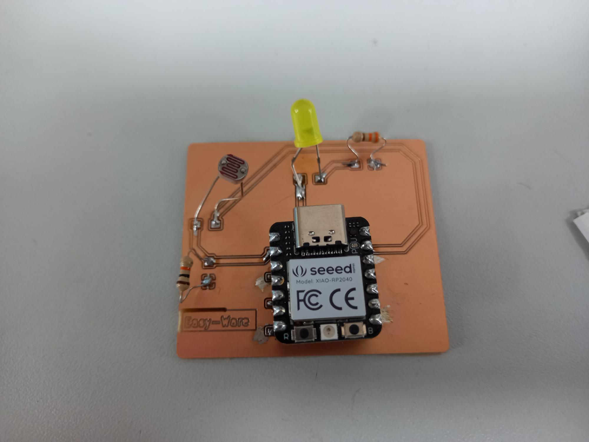
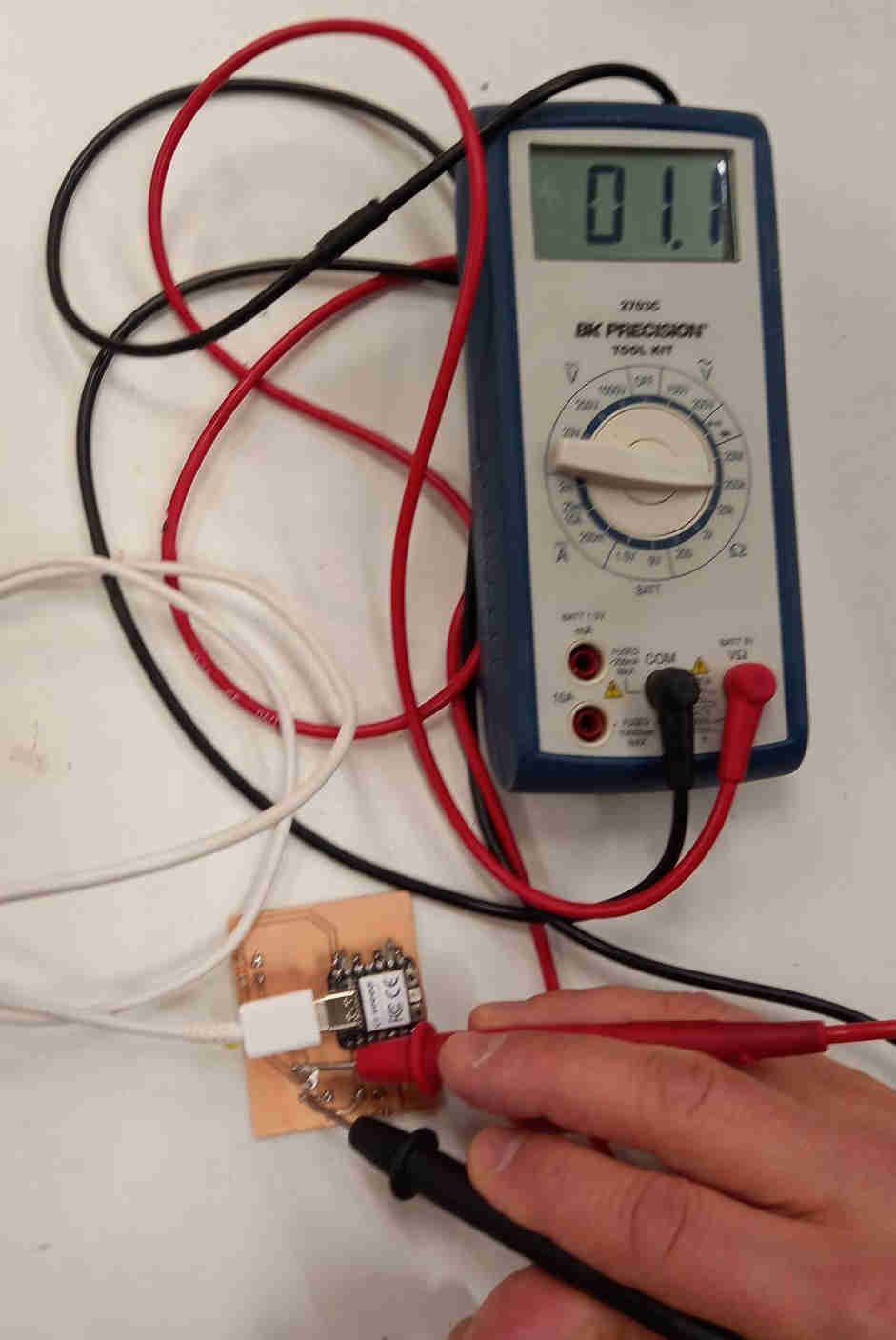
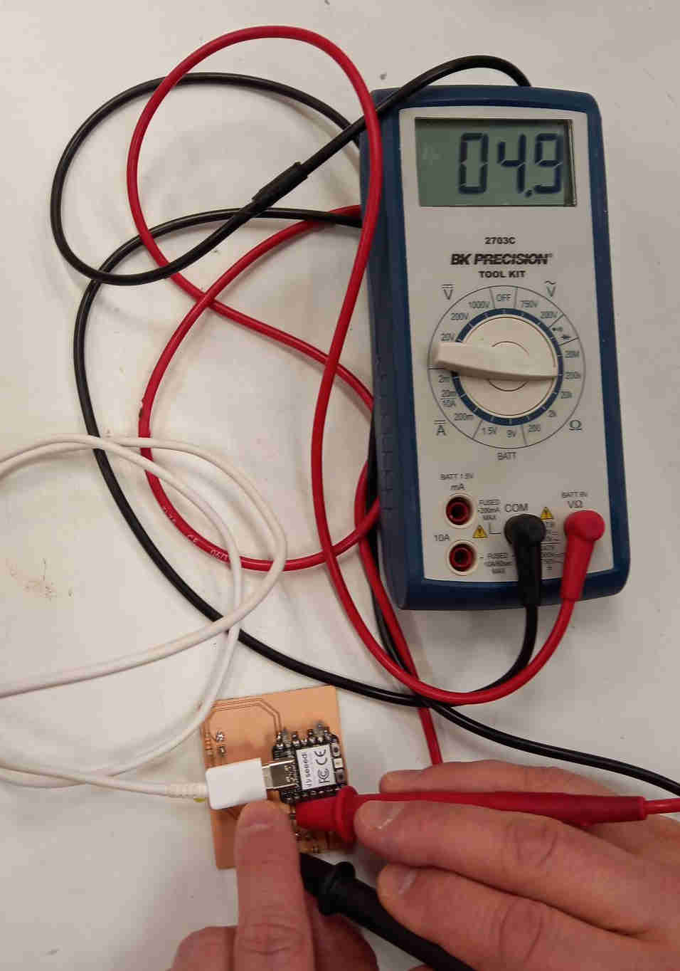
During electronics design week I designed a circuit board that contained a photoresistor and a led, and during electronics production week I milled the board. The photoresistor operates by changing the resistance as function of light. I measured the resistance of the photoresistor when light was coming to it and also when I blocked the light with my finger, so not so much light was arriving to the sensor (some amount of light may pass through my finger).
I used readings from the photoresistor to control led, as described in the documentation of output devices week.
Photoresistor controlled led on my own circuit board
During embedded programming week I programmed a photoresistor controlled led, and during electronics design week I had designed a board for the components (see the links for the original design files). During output devices week I milled a circuit board and soldered the components to it.
I had modified the blink code to read the light level and then turn the led on accordingly using pulse width modulation.
int val =0;
int analogPin=A0;
int lightLevel=1;

// the setup function runs once when you press reset or power the board
void setup() {
  // initialize digital pin LED_BUILTIN as an output.
  pinMode(LED_BUILTIN, OUTPUT);
  pinMode(D1,OUTPUT);
  Serial.begin(9600);
}

// the loop function runs over and over again forever
void loop() {
  //digitalWrite(D1, HIGH);  // turn the LED on (HIGH is the voltage level)
  digitalWrite(D1, HIGH);
  delay(lightLevel-1);                      // wait for a second
  digitalWrite(D1, LOW);   // turn the LED off by making the voltage LOW
  delay(10-lightLevel);                      // wait for a second

  //delay(1000);
  val = analogRead(analogPin);  // read the input pin
  //Serial.println(val);         // print the value to the serial monitor
  lightLevel=map(val,500,1023,1,10);  // map lighLevel to values between 1 and 10
  lightLevel=constrain(lightLevel,1,10); // this clips the values in case they would go above or below 1 and 10
  //Serial.println(lightLevel); // print the lightLevel value to serial monitor

}