15. Wildcard week
This week we had freedom to choose any other digital fabrication method. Since we have access to a higher power laser cutter, I wanted to test metal laser cutting.
First, using FreeCAD, I designed a piece that I could laser cut. The purpose of this piece is to make a strong part for my final project (smart connected recycling cabinet) that would hold the wooden walls of the cabinet in place. The FreeCAD file is here.
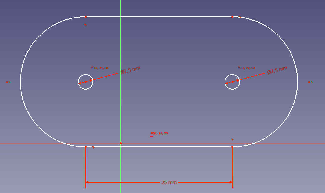
Initially, I made several of the similar parts in the same design and I was thinking to cut them all at the same time, but since we were using scrap sheets from previous projects, we ended up cutting the parts one by one separately at desired positions to use the material optimally.
The software that was used for operating the laser (LaserLink) could import DXF 14 files. To convert the files from freecad to this format, I used inkscape. First I exported the schematic from FreeCAD to svg file and then opened that with Inkscape and exported it to DXF 14 format. The svg file is here and the dxf14 file is here.
There is a instructional video on youtube for using the laser cutter made in our fab lab (link). Otherwise the figures in this page are my own, but I included two screenshots from the video (indicated in the figure captions), to show where some of the appliances are turned on and off so the procedure and the tools can be understood and also I would remember what to do next time I would use the cutter.
The procedure consists of the following steps:
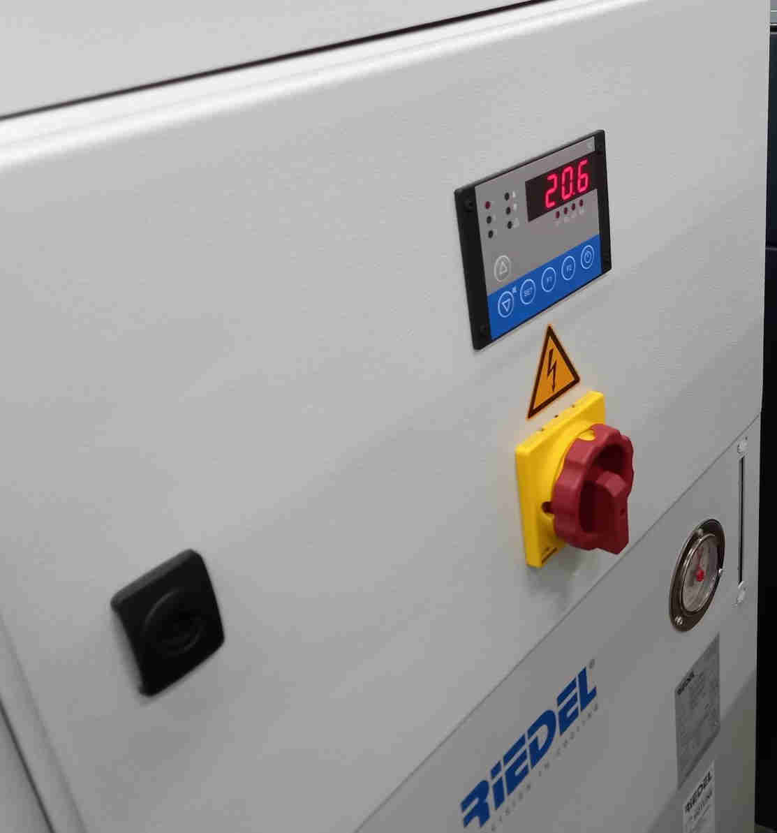
- Start the water cooling system
- (Optionally) start the extra ventilation
- Wait at least 20 seconds
- Start the computer
- Open the nitrogen bottle valve
First we turned on the water cooling system.
As indicated in the figure, it can be sometimes be necessary to turn on the extra ventilation system (we did not use extra ventilation during these cuttings, since they were very small cuts).
After this we started the laser.
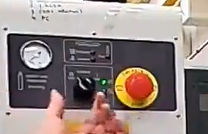
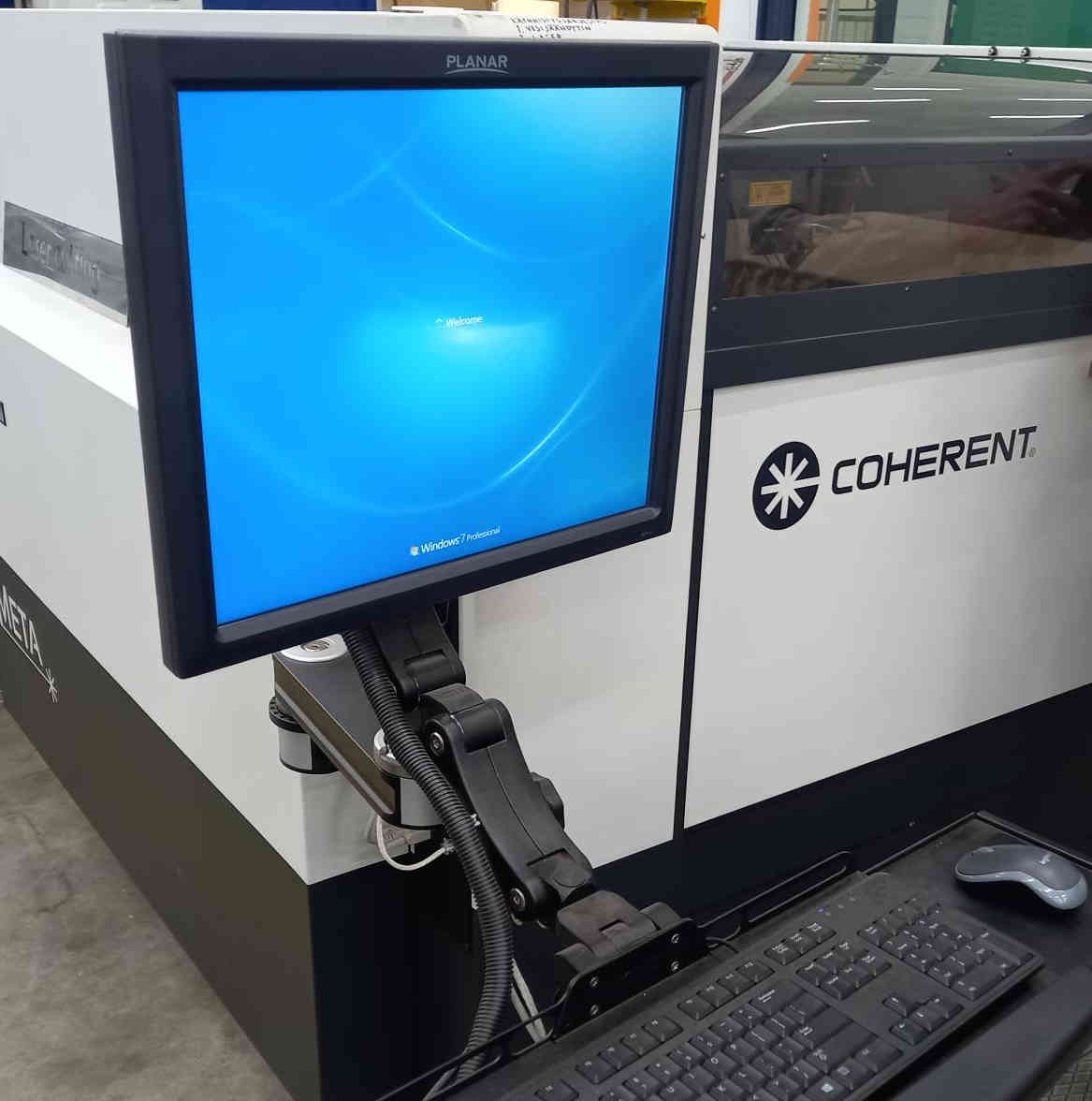
Then waited for more than 20 seconds, and turned on the computer.
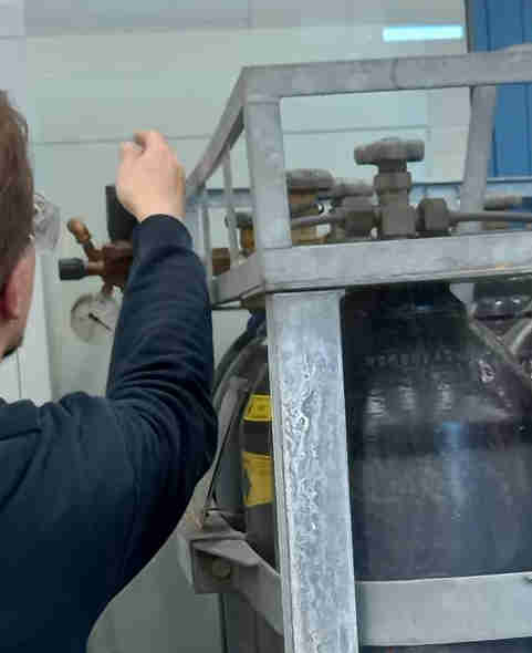
Then we turned on the nitrogen gas inlet by opening the bottle valve.
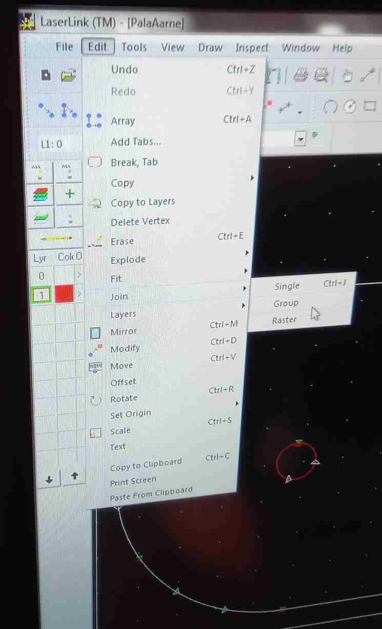
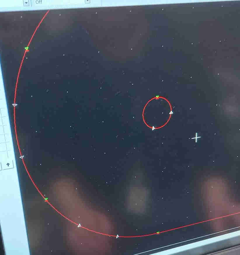
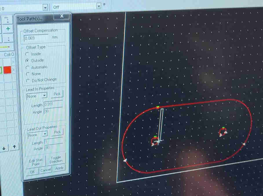
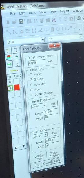
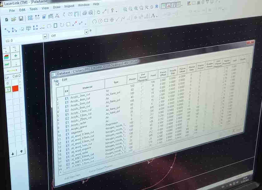
We started the LaserLink software. The dxf (14) file of my design was imported to the software. It was necessary to make some modifications to the paths. The points needed to be grouped and joined and lead in and out were introduced to the toolpaths.
After the toolpaths were ready, we chose the cutting material from the database.
Then we cut the parts using the laser. After we had cut all the parts, we turned the system down. The procedure for this is (as also described in the video):
- Switch off the nitrogen bottle valve (check pressure from the attached meter)
- Turn off the laser and press emergency stop switch
- Shut down the computer
- Switch off the cooling water. After long cut wait until the laser has cooled down first.
- Turn off the extra ventilation (if used) by pressing button own for a few seconds.
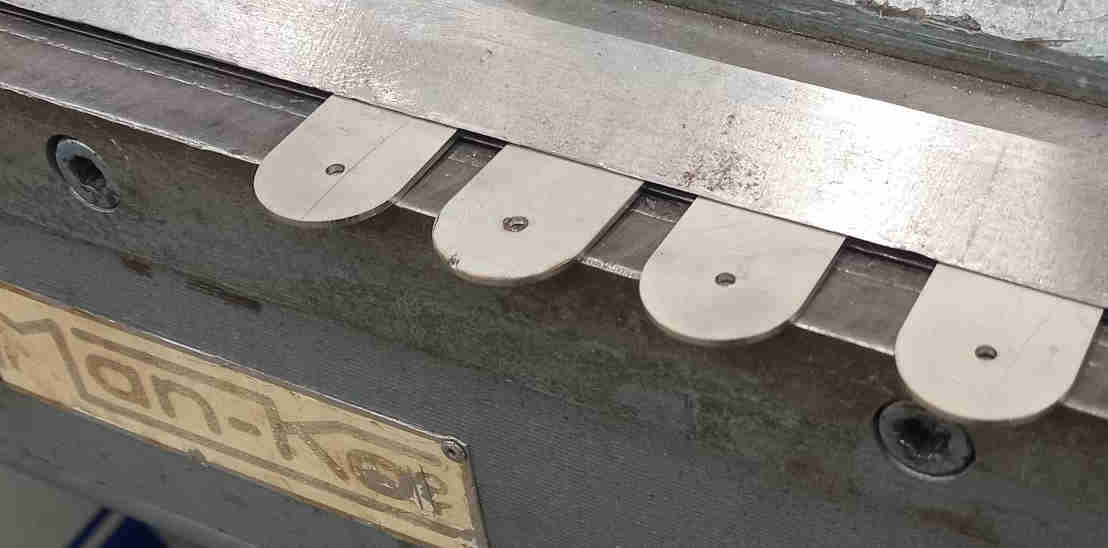
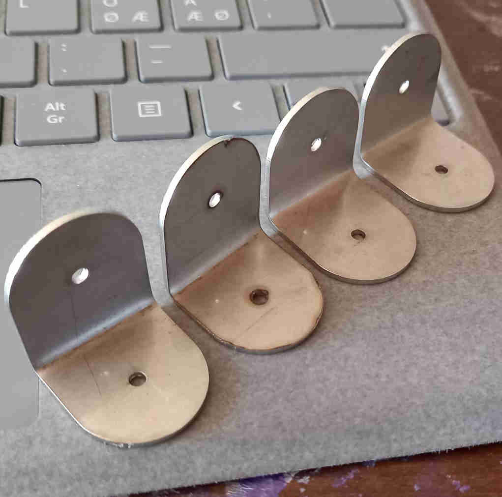
I needed to bend the parts in to 90 degree angle in the middle to obtain the desired shape so that I could use them in my final project. I used the manual bending machine.