3. Computer controlled cutting
This week we focused on computer controlld cutting using laser cutter and vinyl cutter.
In the group work we investigated the laser cutter operation: we measured the kerf (i.e. the excess material burned next to the cut line) of the laser cutter by cutting a test piece and measuring it's dimensions.
We tested the effect of focus of the laser cutter by adjusting the focus to different offsets. It was seen that 1 mm difference did not affect the result much, but 4 mm difference affected the result quite much. Interestingly, when the focal point was 4 mm above of the surface, the laser did not cut through the material. However, when the focal point was 4 mm below of the material the laser was able to cut through the material. Aleksi had good interpretation of this, and a schematic describing the condition was added to the group work page. The main reason for this effect was that when the focal point was above of the material, the energy was deposited to a larger volume than when the focal point was below the surface. When the focal point is correctly at the surface, the laser energy is deposited to the smallest volume on the surface, and effectively cuts the thinnest line.
We tested the effect of cutting speed and power. Here, fundamentally the result is affected by the power deposited to volume on the surface. Both speed and power affect this. If the speed was too high, the laser did not cut through even at the highest laser power. Also if the laser power was too small, the laser did not cut through even for the lowest speed.
We tested how the speed and power of the laser affected the contrast in the laser engraving. It could be seen, quite naturally, that the lesser power caused smaller contrast, and slower speed caused higher contrast.
We also tested how the dots per inch (DPI) setting affected the result. Quite naturally, the higher the DPI was, the higher the contrast.
All these observations can be understood on the basis of how much laser energy per time (i.e. power) is deposited on the material volume at the surface. Higher power burns the material more effectively.
We made test cuts, where we included the kerf in to the design, and other cuts without the kerf. It could be seen that the kerf should be taken in to account in order to achieve tight fit for attached snap fitted parts.
Vinyl cutter
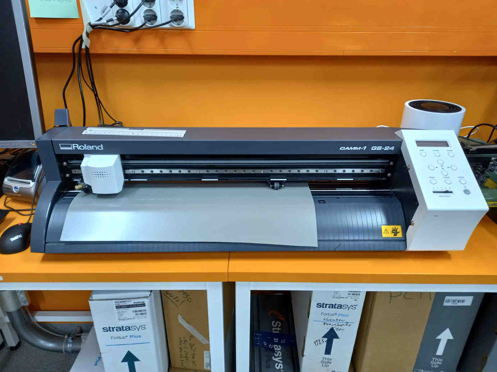
I used Roland CAMM-1 GS-24 vinyl cutter to add an image to my old work laptop. The vinyl cutter is relatively straightforward to operate:
The vinyl rolls are located next to the machine. Some leftover pieces, as well as tweezers, are stored in the cabin above of the rolls.
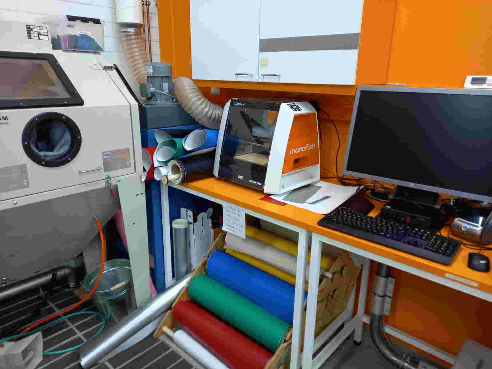
On the machine, there is on/off switch and a switch to set origin.
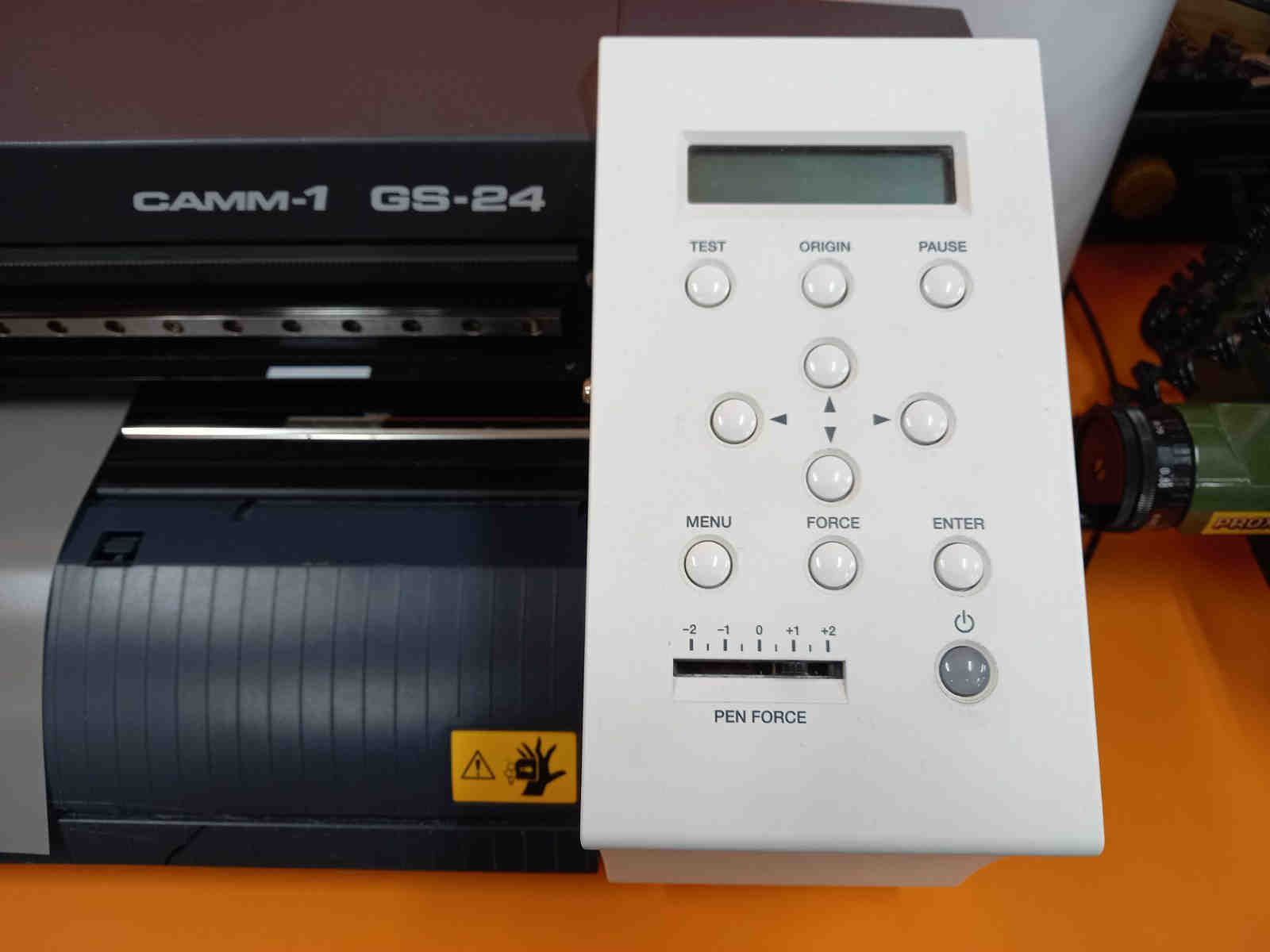
The suitable places for the origin are marked on the vinyl cutter with white lines. I set the origin on the left-most place when doing the cutting.
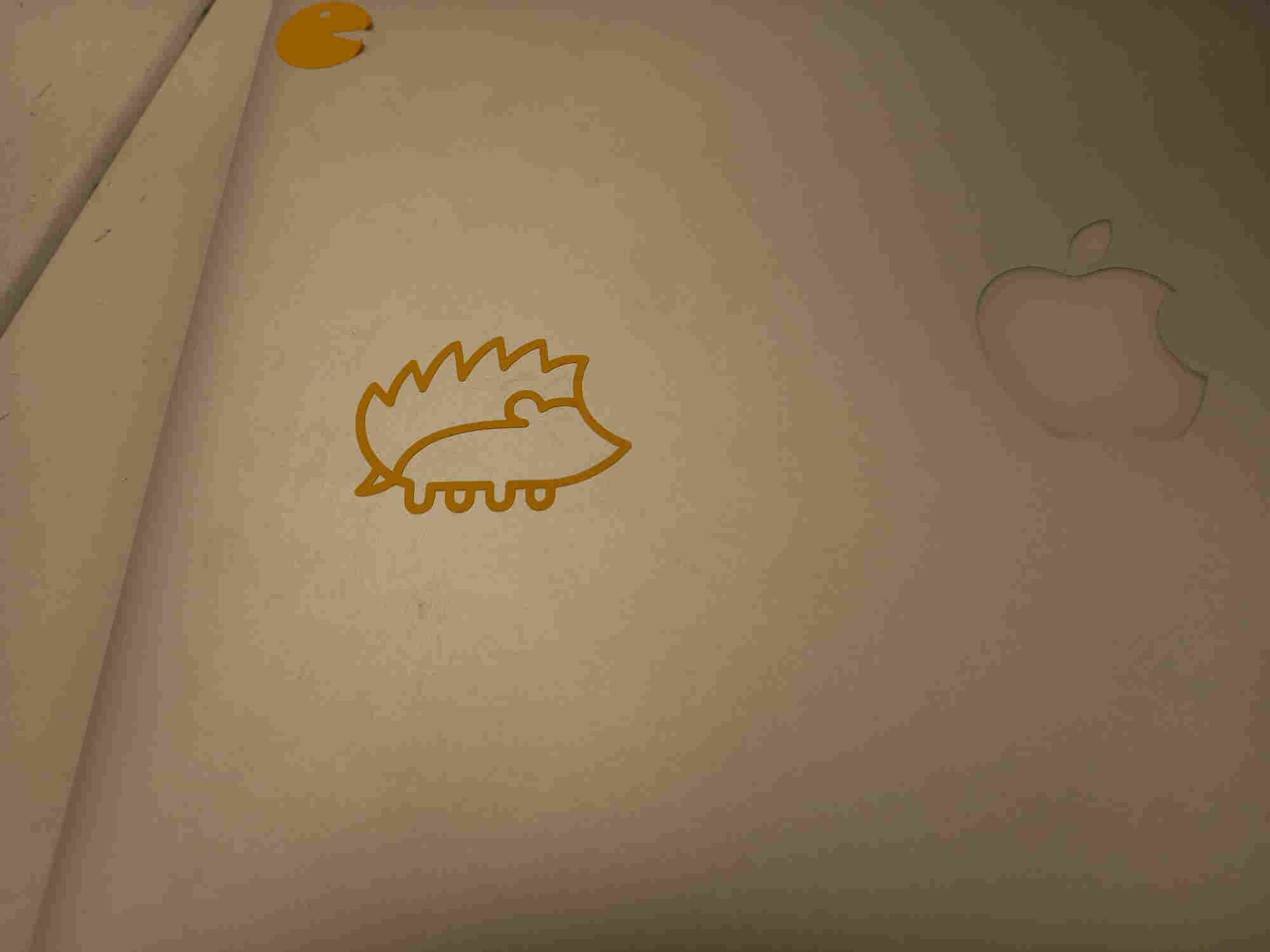
I downloaded an image of hedgehog, created by Freepik: Hedgehog icons created by Freepik - Flaticon
I opened the file using Inkscape. I used trace bitmap command to extract the lines from the image. I set the line thickness to 0.5.
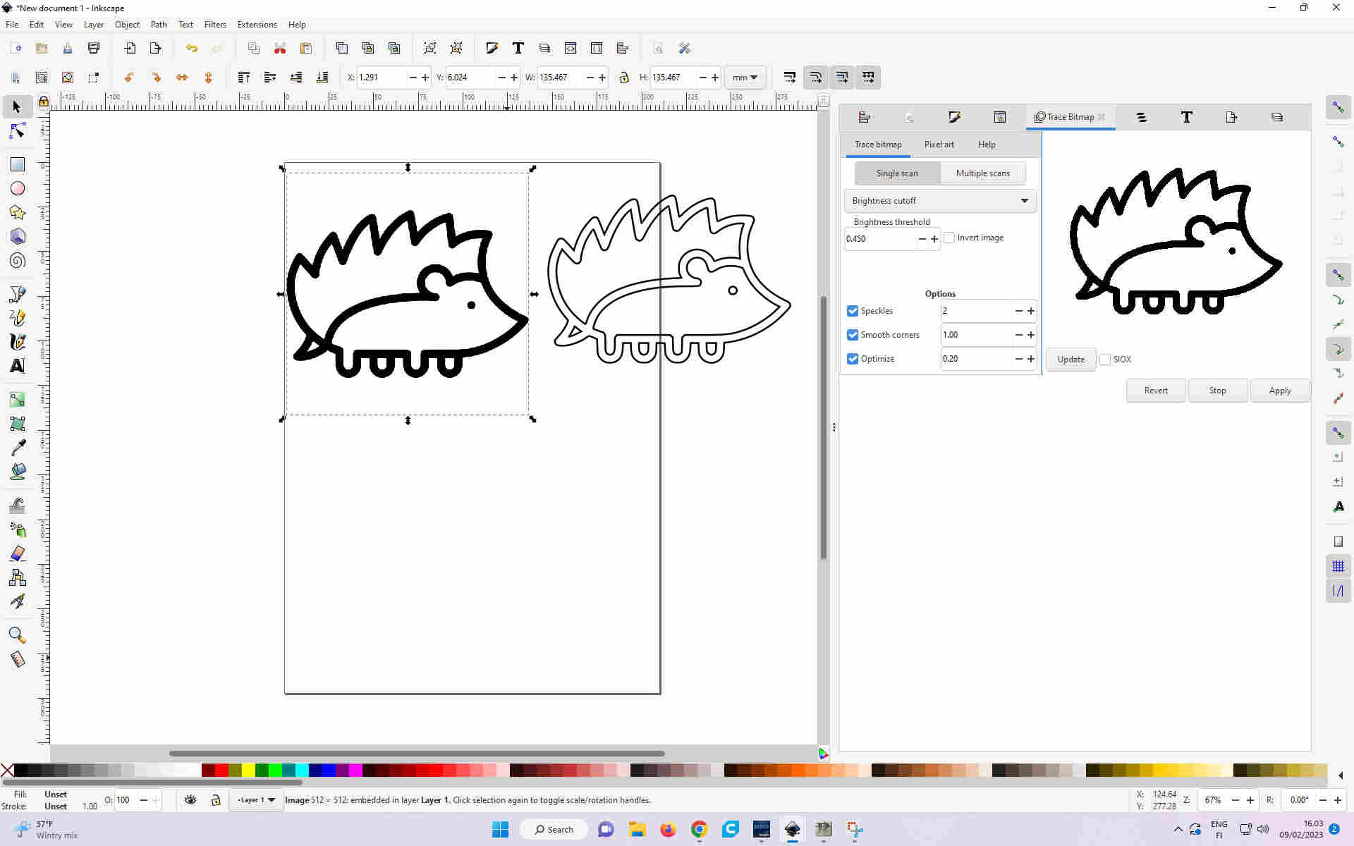
The hedgehog file, saved as svg is here.
Using Inkscape extension, which was installed on the inkscape of the Oulu fablab, I exported the figure to the Roland Cutstudio program.
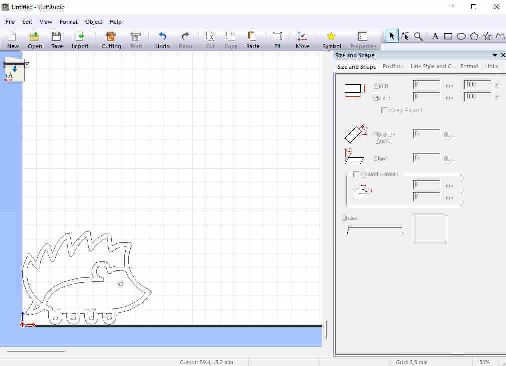
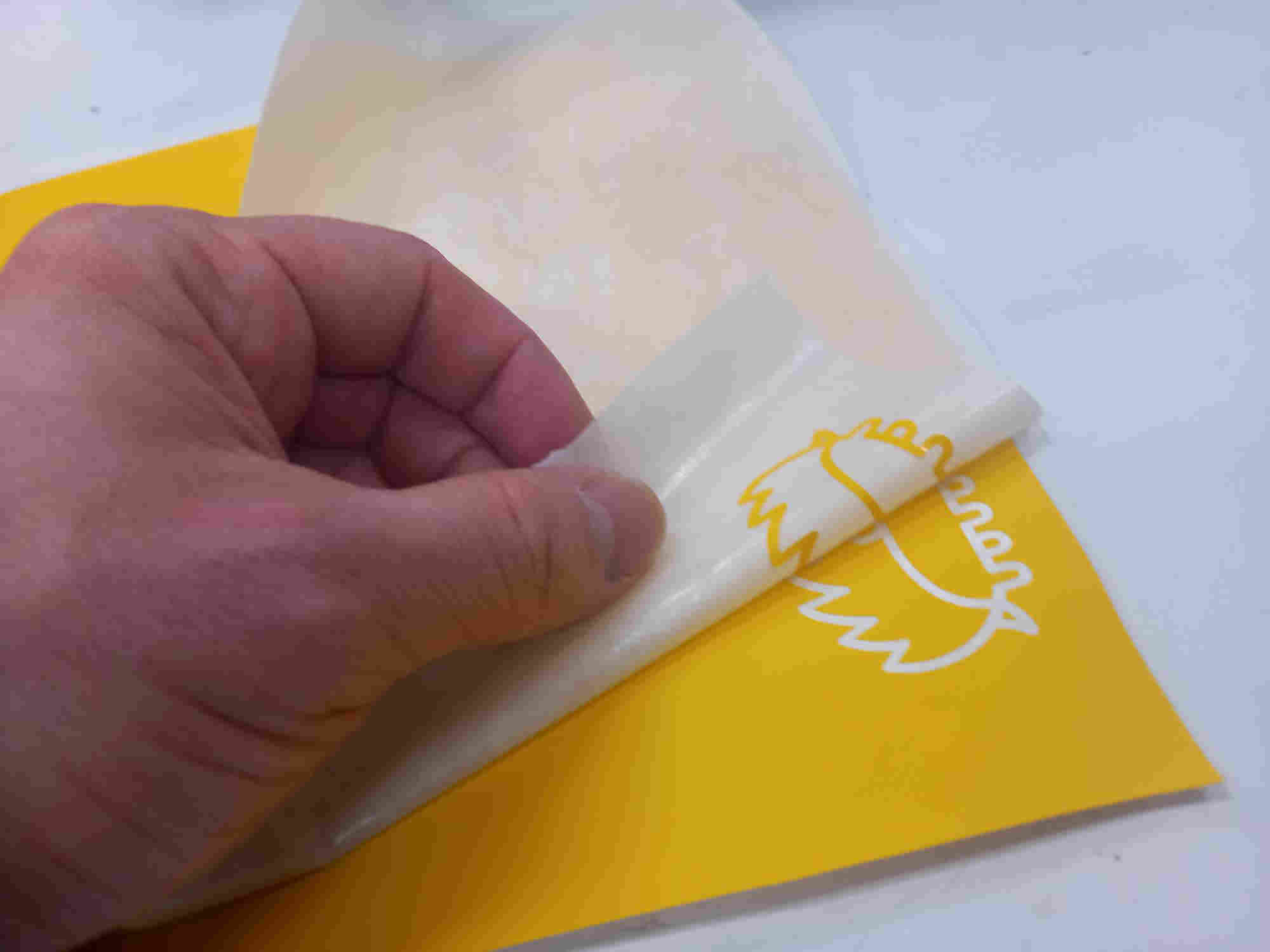
I printed the image, and it was cut by the vinyl cutter. I then took glue paper and transferred the vinyl to it. At the same time as I was transferring the vinyl pieces that I wanted to keep in the final transferred image, I used tweezers to hold down those pieces that I did not want to include in the transferred image.
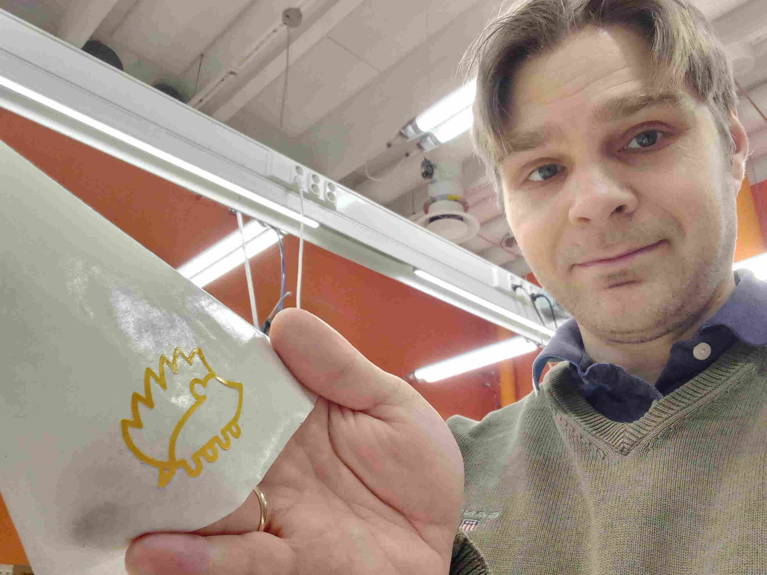
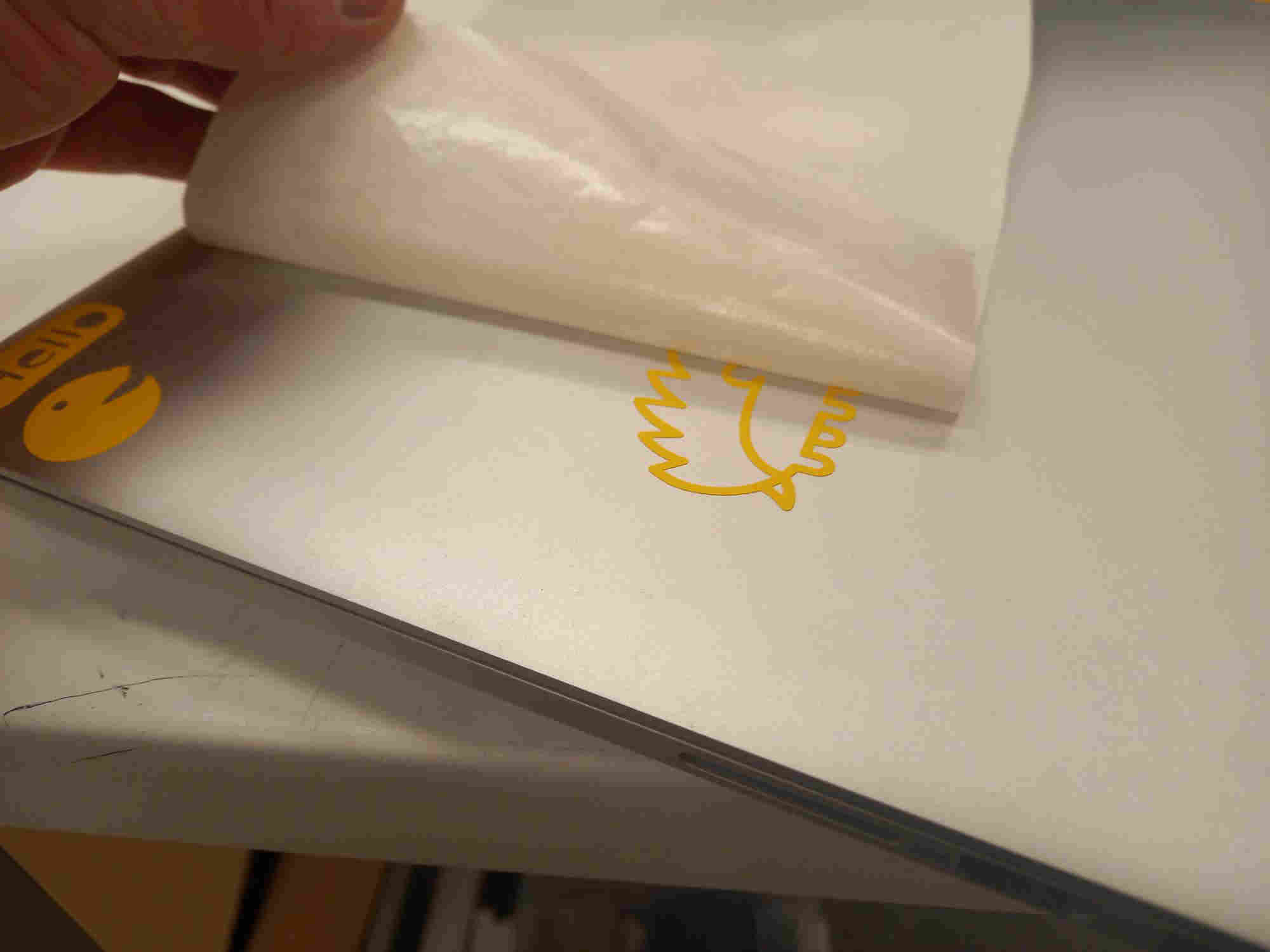
I then transferred the vinyl to the laptop.
Laser cutting
For laser cutting Oulu fab lab is equipped with Epilog Fusion M2 40 75 watt Laser. The laser cutter. The image that will be cut and/or engraved is sent to laser in a similar way as it is printed with a normal printer. The lines that will be cut, are defined by line thickness, which need to be defined very thin: 0.02 mm. Lines that are thick will be engraved.
The image file can be prepared with inkscape, as described in the previous week’s assignment, where the line thickness can be set. The file is saved as pdf file and the opened with Acrobat reader. Then the file is printed. The settings for the laser can be accessed through the properties -> advanced tab in the printing dialogue. There the material, and the material thickness, and selection for cut and/or engrave can be chosen. Here, I only wanted to perform cutting of 3 mm HDF material, so I chose settings for it and clicked load. Then I closed the dialogue and selected print. This sent the file to the printer.
In the printer, I need to select origin in the x- and y- direction (along the table). This is done by choosing “jog” in the menu. To show the position accurately, a red laser pointer can be turned on. The origin can be moved with joystic and it is setting by pushing the joystick (the joystick acts as a button also). After setting the x- and y- origin, it is necessary set the focus in z-direction. This is done with the aid of a calibration test piece, which can be temporarily attached to the laser. By choosing focus, and then moving the table up and down so that the test piece tip touches the plate which will be cut, the focus is set by pressing the joystic.
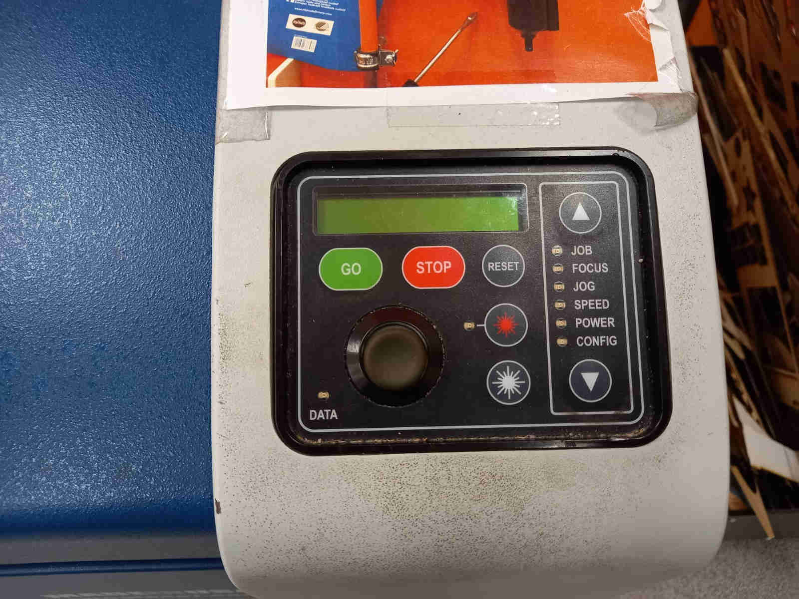
After these calibrations the image is cut by pushing the green button.
When the laser is cutting and/or engraving, it is necessary to observe it continuosly, so that in case of fire would ignite, the machine could be quickly turned off (and electricity should be also switched off), as well as the air inlet. If the fire is not extinguished, there is a fire blanket near the laser cutter, as well as a fire extinguisher, which would be the last resort.
Construction kit
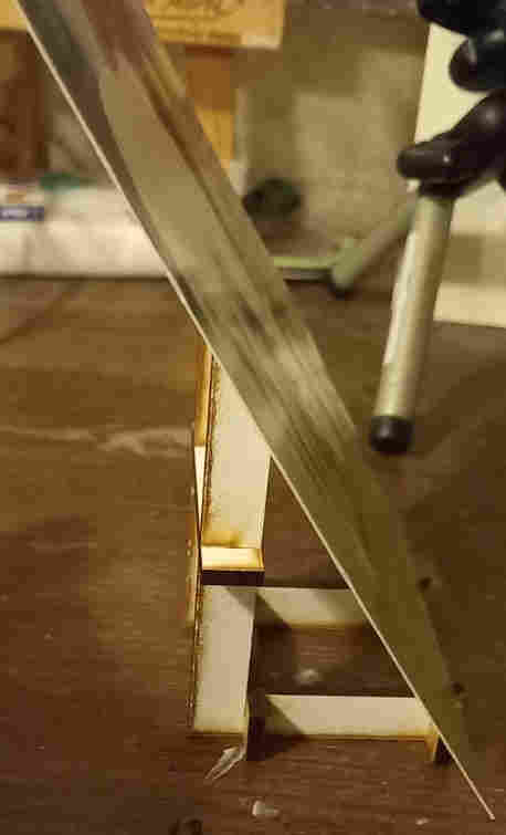
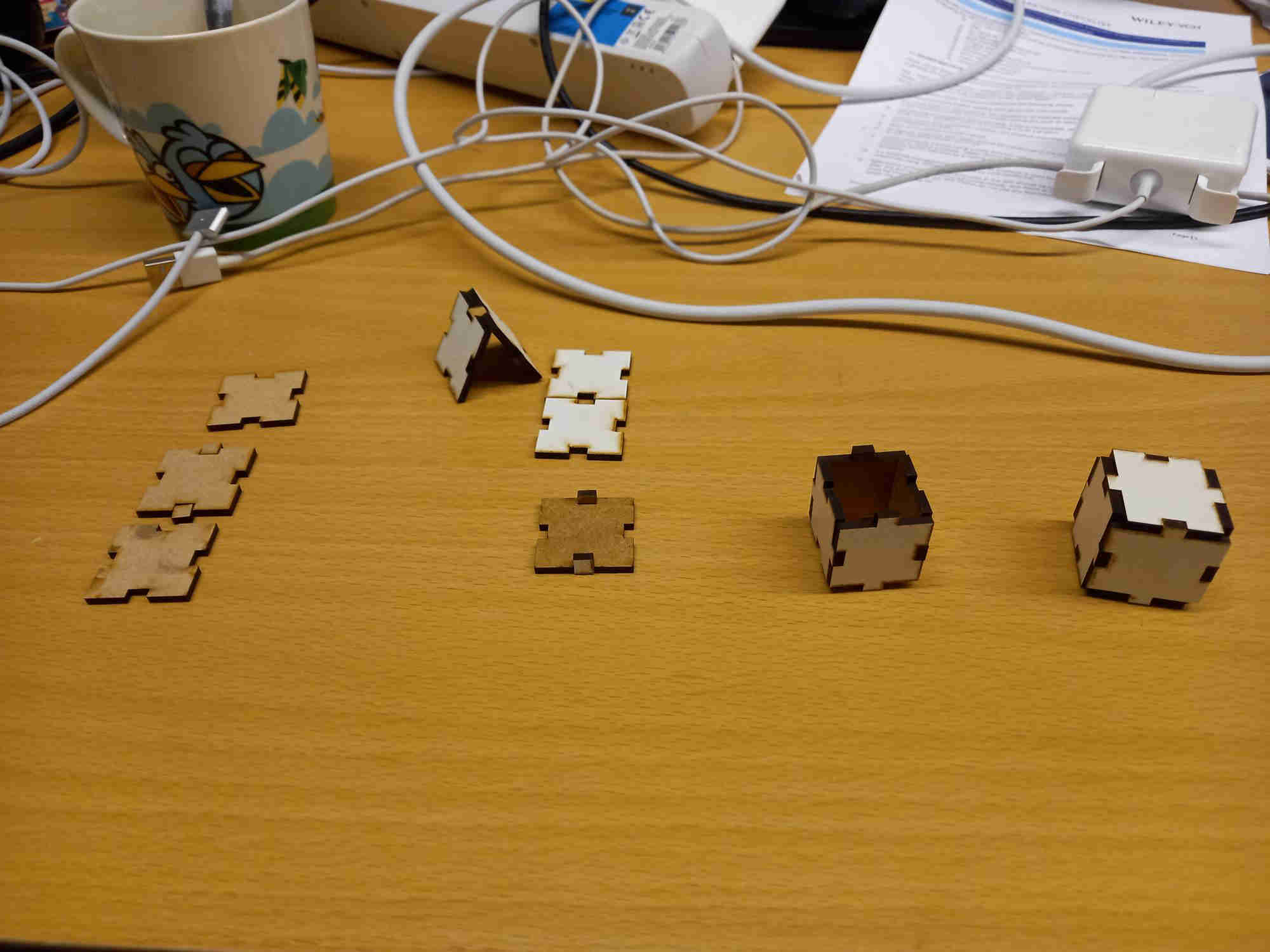
I started to test a possible design for a snap fit constuction kit. My idea was to make a construction kit, that one could assemble to different types of rectangular structures. Then I thought to extend it to have gears, so a simple kind of mechanical machines could be constructed with it. To take in to account for kerf (i.e. the amount of material cut away by the laser beam), I added it to the parametric design. I also added dimensions, such as the length of the side of the construction piece, a segment length as well as the thickness of the material as parameters to the design. To add the gears, I had to cut small cylindrical pieces of wood with saw as shafts, since I could not cut longish circular objects. They could be also made using 3d printing. I did the parametric design using FreeCAD in the same way as in the previous weeks assignment. First I made two pieces, a larger piece and a small connecting piece. I did few tests to get the the connecting piece to fit tightly. Then I realized that it is not a good idea to cut very small pieces, since they could easily drop through the grid on the laser cutter plate holder. Then I changed the design to consists of a single one-piece part. This was quite ok, but I needed to adjust the vertical and horizontal distances, so that they would be equal after assembly.
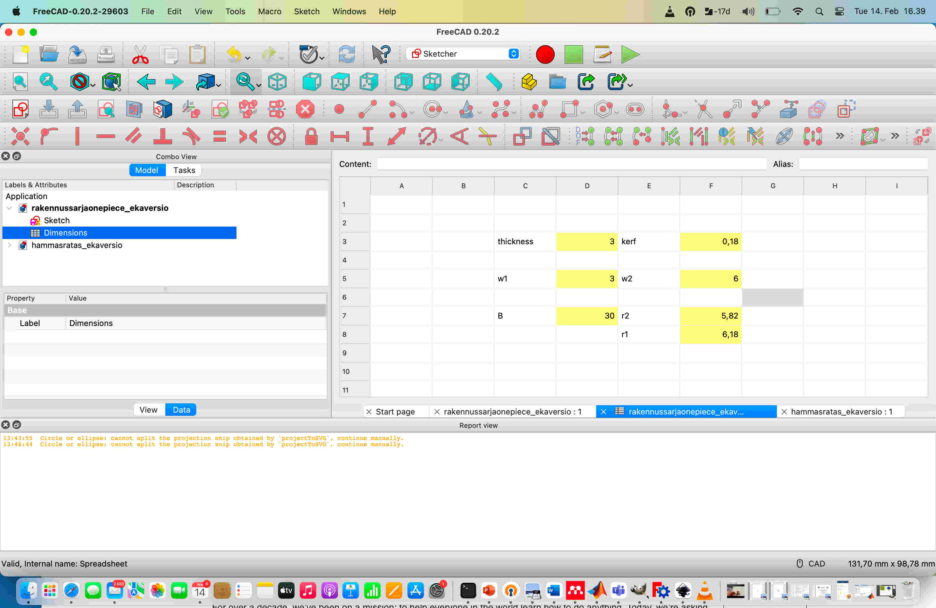
In laser cutting, there is need to account for the kerf, which is the thickness of material removed by the laser cutter. To make the parametric design, and to account for the kerf, I created a spreadsheet: pull down menu (which initially has start and blue arrow in it) -> spreadsheet. Then from top menu I chose the spreadsheet icon.
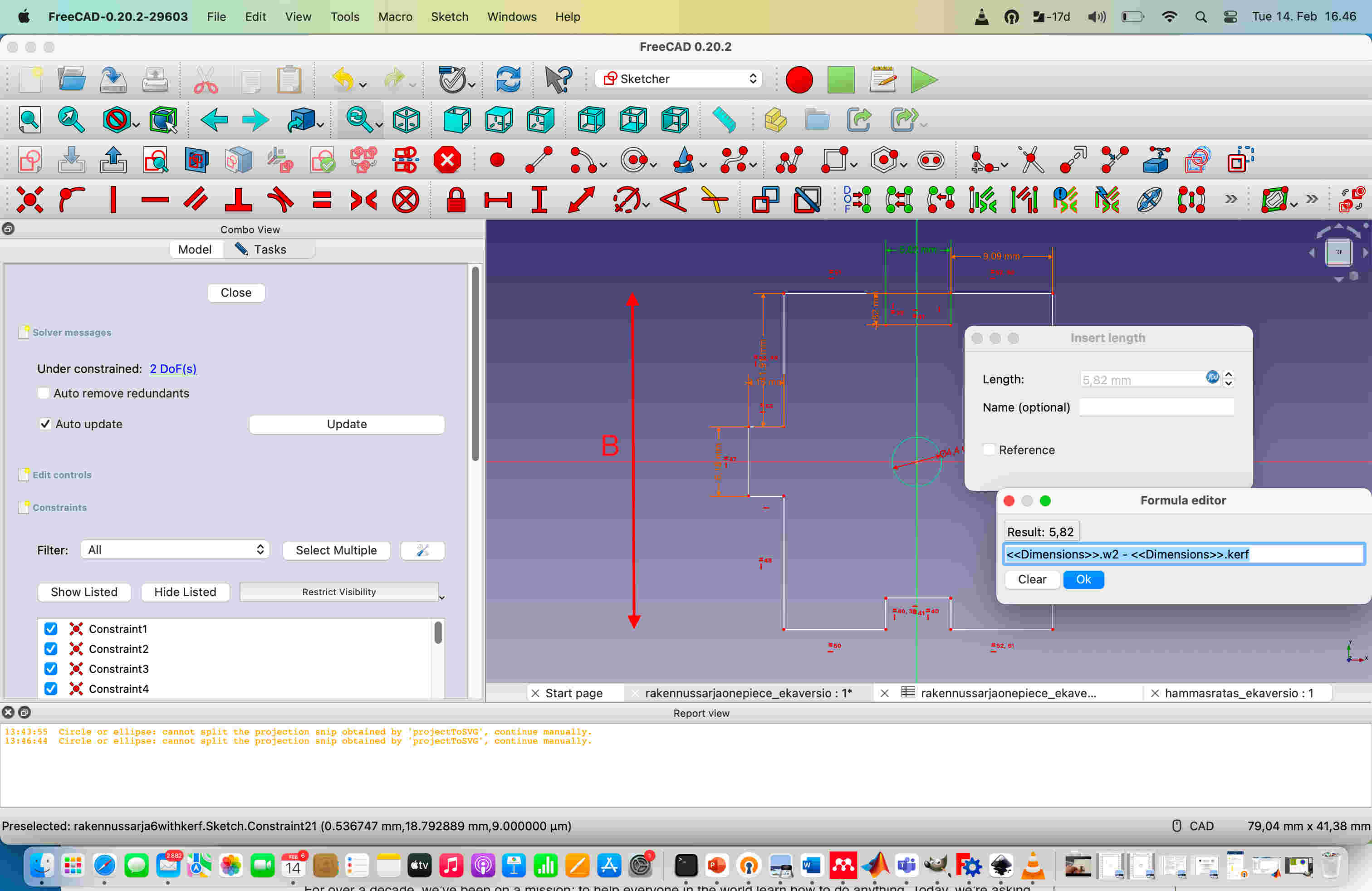
In the spreadsheet I inserted the parametric values, kerf being one of them. The other parameters are the side length (B shown in the images below) of the part, and the length of the protruding attaching shape of the part (w2) and thickness of the material. I created alias for the parameters that I would want to reference in the design. The alias could be created by typing the name of the alias to the text box on the top right corner next to text “Alias:”. The kerf affects the dimensions: for those parts that protrude outwards, the kerf needs to be taken in to account by adding it to length (since the cut will be smaller). Those parts that are inwards to the designed shape, the kerf needs to be subtracted from the lengh (since the cut will be larger).
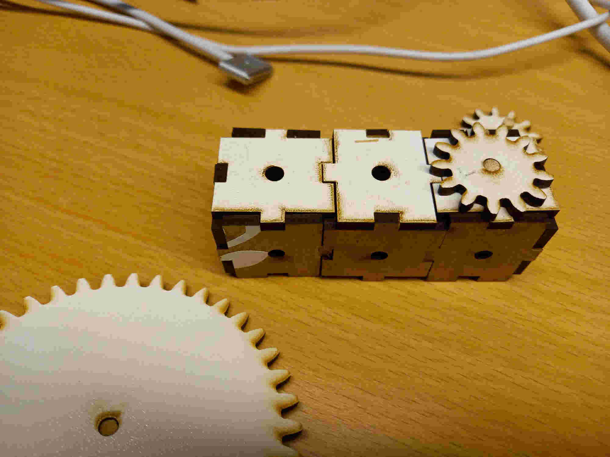
Since it was mentioned in the nueval that just a snap fit box would not be enough, I thought to add some features to the construction kit. I added gears, so that it would be possible to do mechanical gear design attached to the structure. As a first step I added small shafts to the gears by cutting a rod. The gears could be automatically made in FreeCAD in the part design environment, choosing part design -> Involute gear.
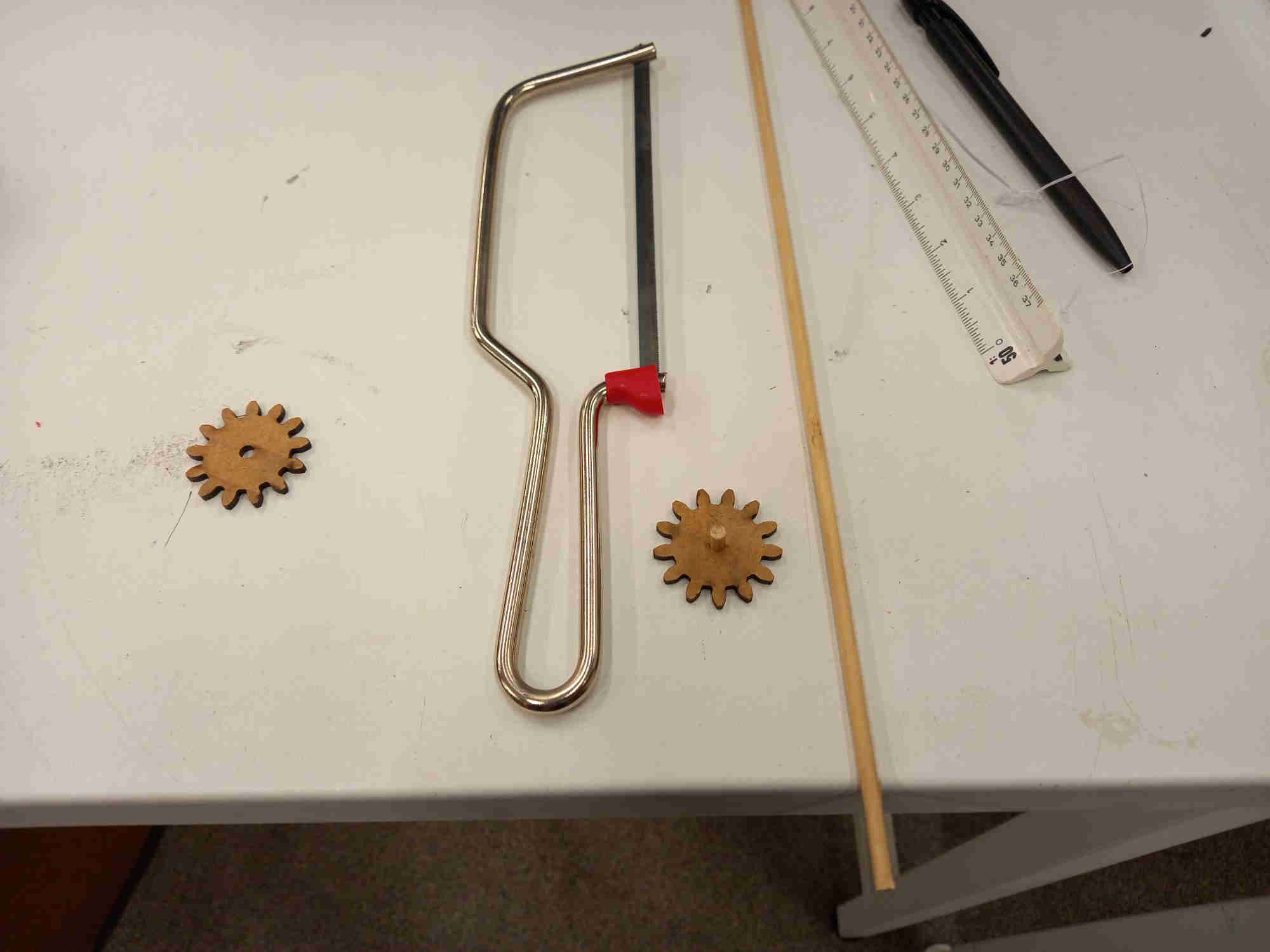
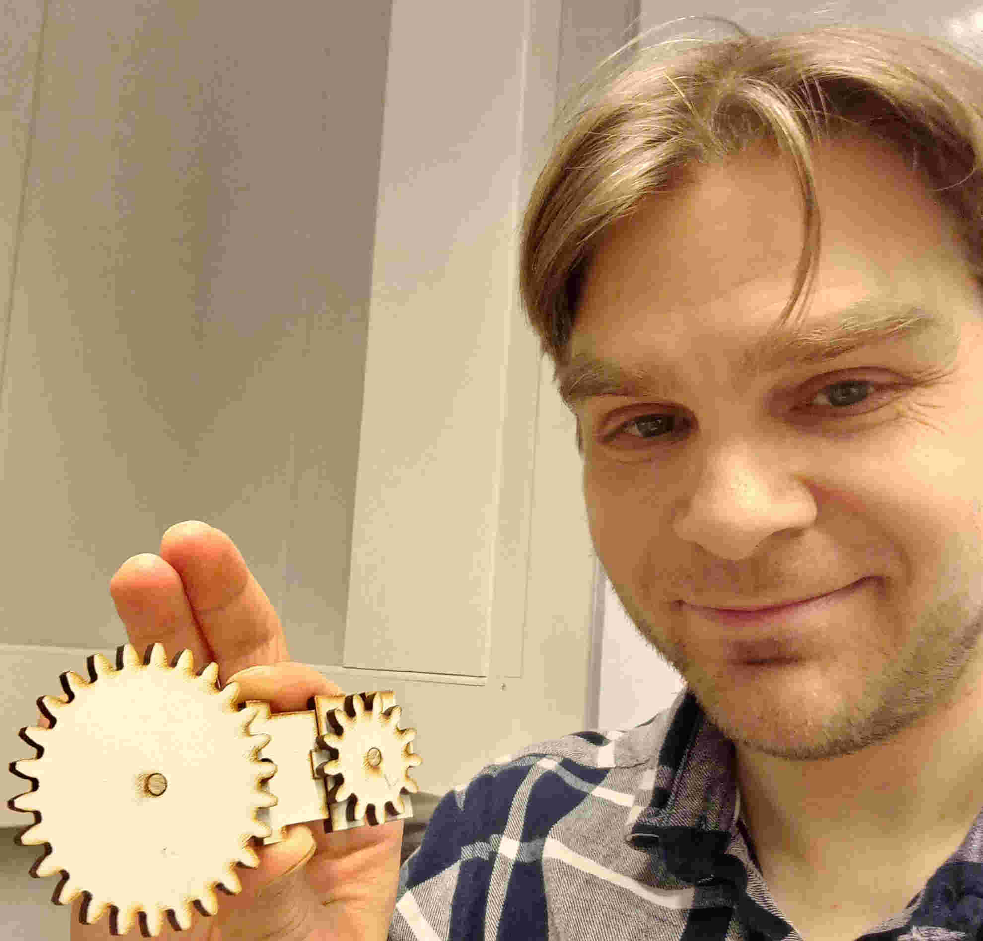
Then I made a simple assembly to test the operation of the gears.
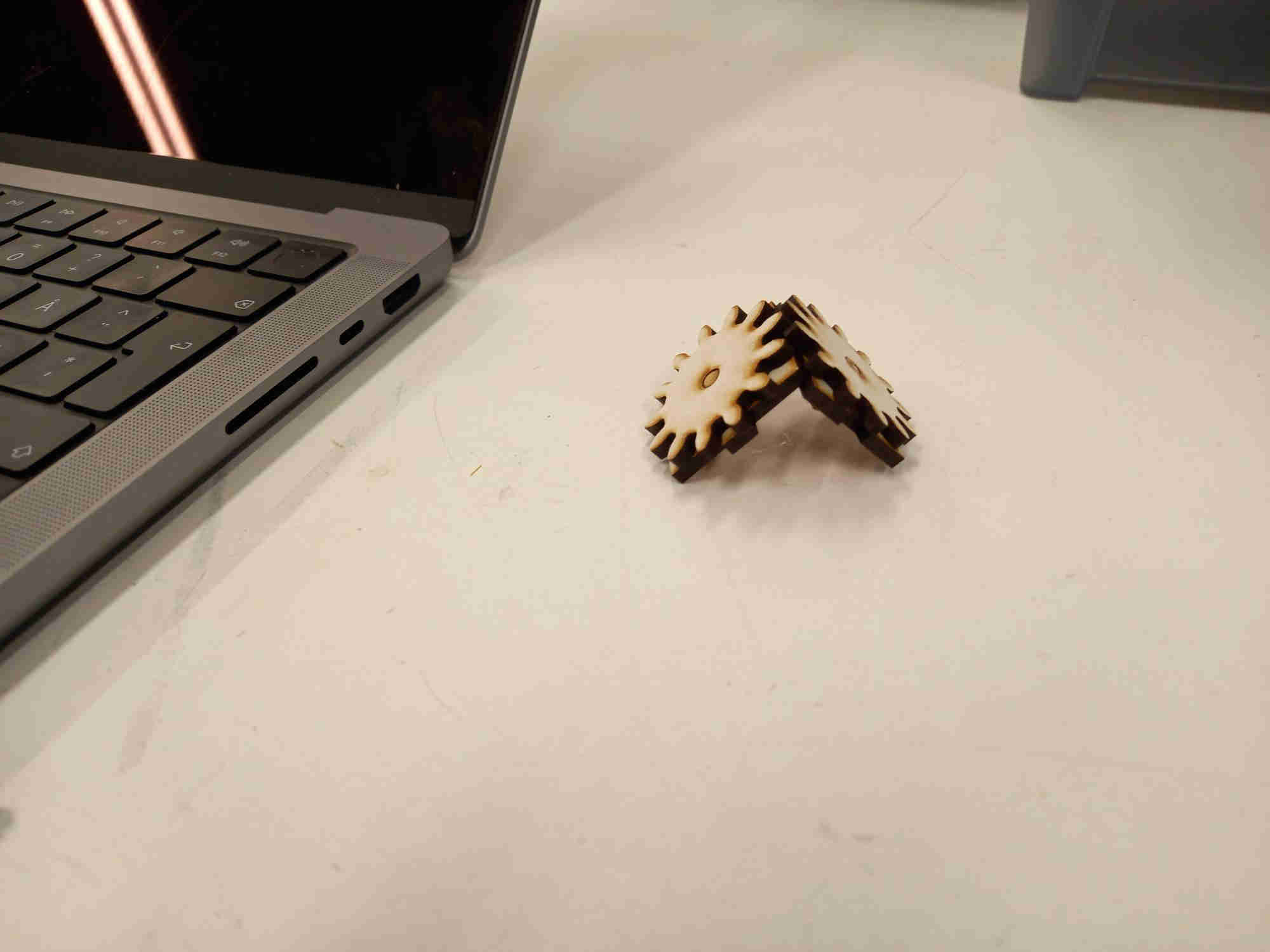
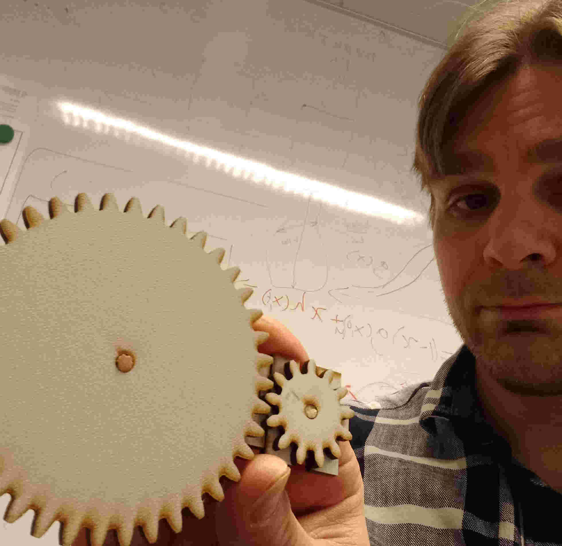
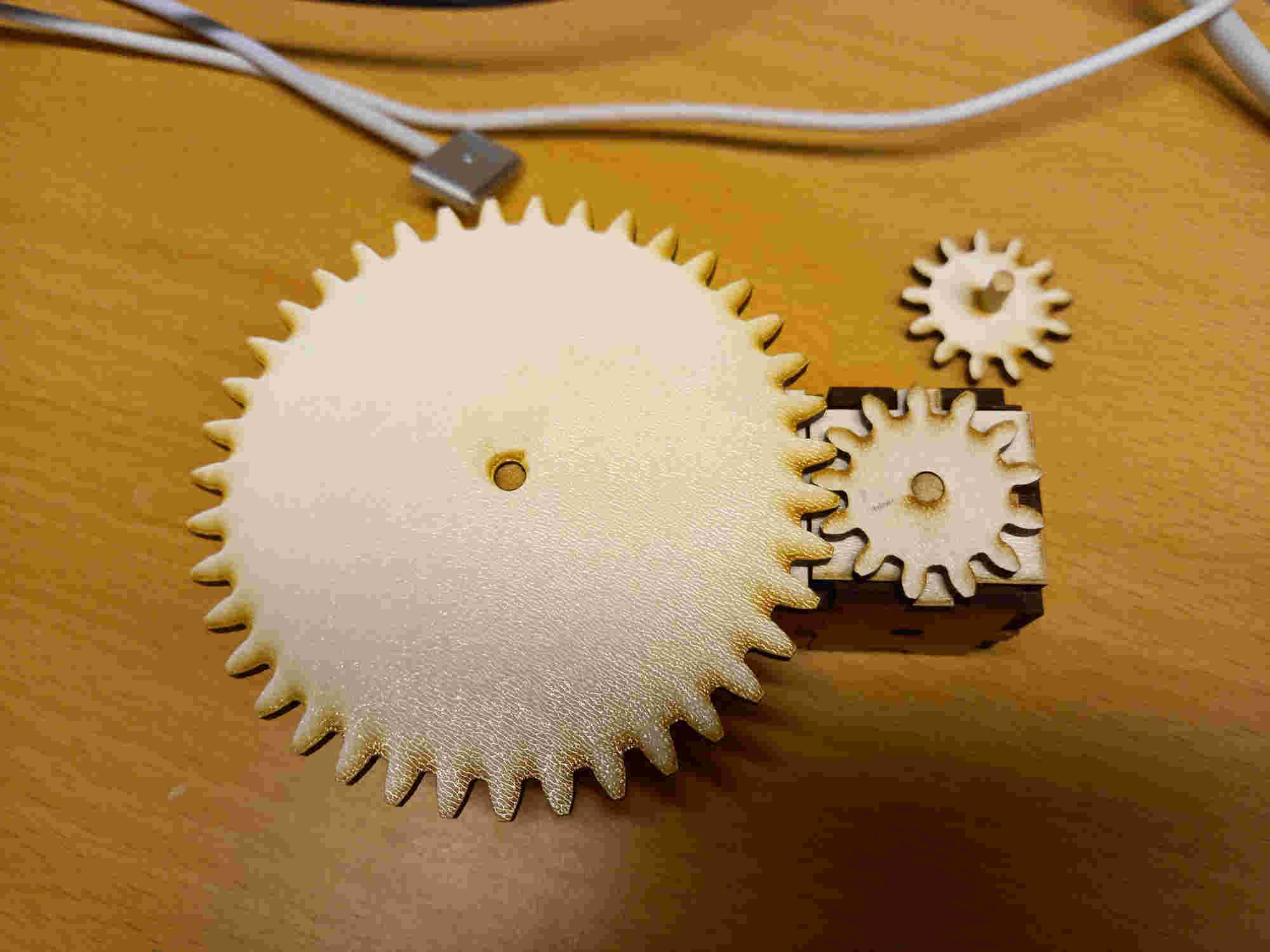
After this I thought to try different sized gears, and assembling them to a constructed structure. I experimented with different gear sizes, and after a while I got them match reasonably well. The gear design is not parametric, but the structure is parametric. Also, the gear needs a shaft, which I cut out from a rod. Perhaps the gear could be made parametric and 3D printed.
freeCAD file for the structure piece.
STL file for the structure piece.
freeCAD file for the gear pieces in the first video.
freeCAD file for the gears in the second video.
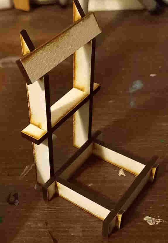
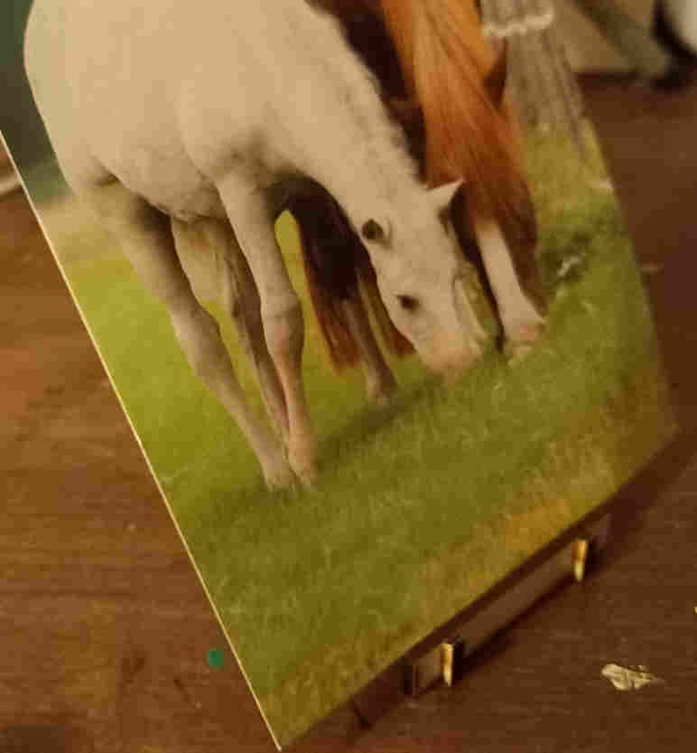
Laser cutting and assembling post card stand
Additionally, I used the laser cutter to cut the postcard stand which I designed for the computer aided desing week.
The laser cut parts fitted well together, and the end result was rigid. It also fit the design purpose quite well, alhtough it might be good idea to make it slightly more wider to hold the postcard even better.