5. 3D Scanning and printing
This week we focused on 3D scanning and printing. We did group work on printing different test pieces with different printers.
Few conclusions from the group work: It appears that the Fortus 380 mc had some problems with the test print. There was some "spaghetti", when the overhang angle was such that the structure was near horizontal. When the deviation from the horizontal was less than 30 degrees, there was significant amount of spaghetti like structure. There was stringing between the structures. Also for the clearance test, only the most largest clearances (larger or equal to 0.7 mm) allowed movement of the separate pieces. For the Fortus printer, the holes deviated a bit from the designed circular shape. Fortus also was not able to print fine walls.
Also Raise 3D pro2 had some roughness below the structure when the deviation from the horizontal direction was less or equal to 20 degrees.
The diameters were printed quite accurately with all printers, but Ender 3D pro 2, which had somewhat more deviation from the design (7.5 mm versus 8.0 mm design and 6.5 mm versus 6.0 mm design).
3D scanning
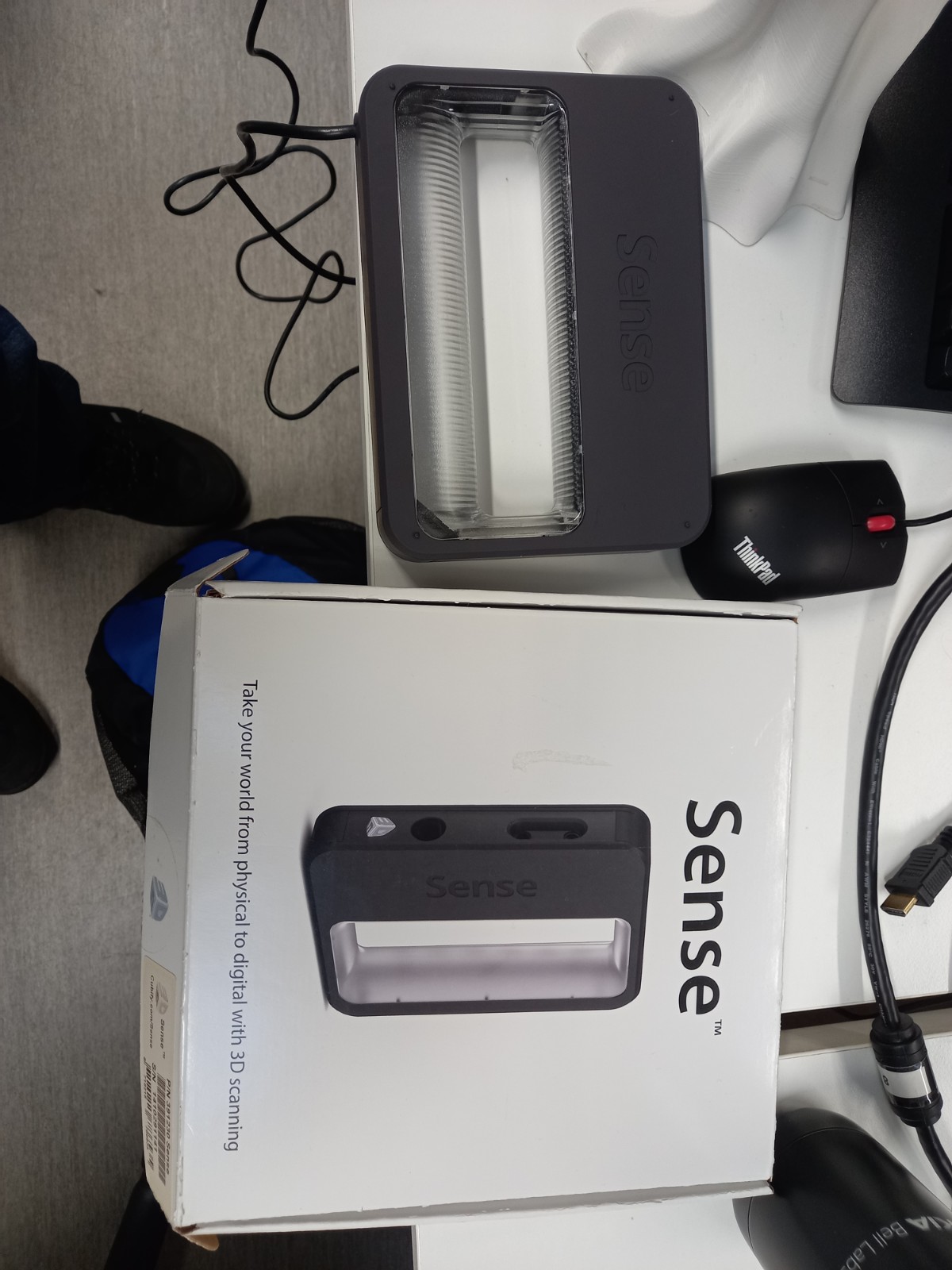
First, we tested hand Scanner named Sense with Abishek.
I asked Abishek to scan me. I was sitting on a chair that could be rotated and he pointed the hand scanner to me while I rotated. The result was quite funny. I appear to have look like a zombie, and have about three noses, with a hook on the tip of the main nose.
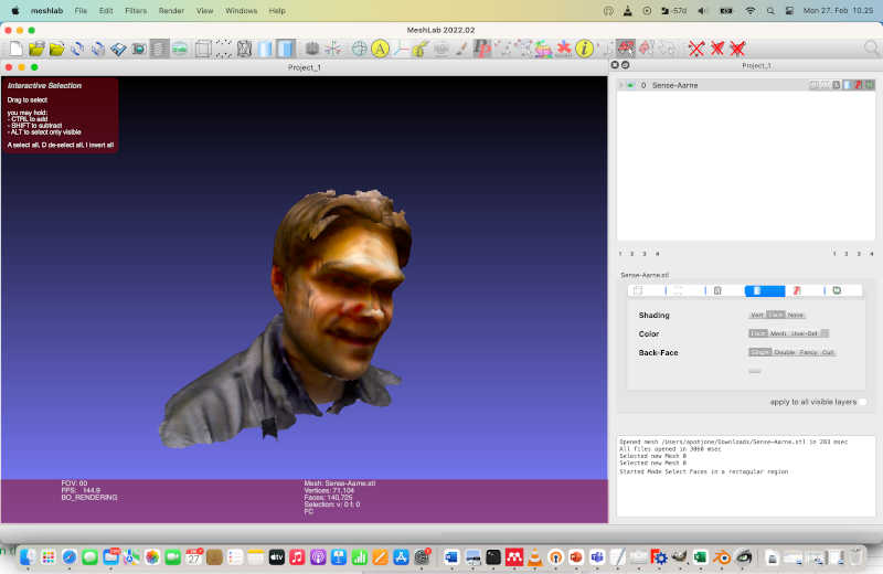
I modified the file a bit with meshlab. I removed the hook and filled the holes. This might make the stl file printable, but I did not try it yet.
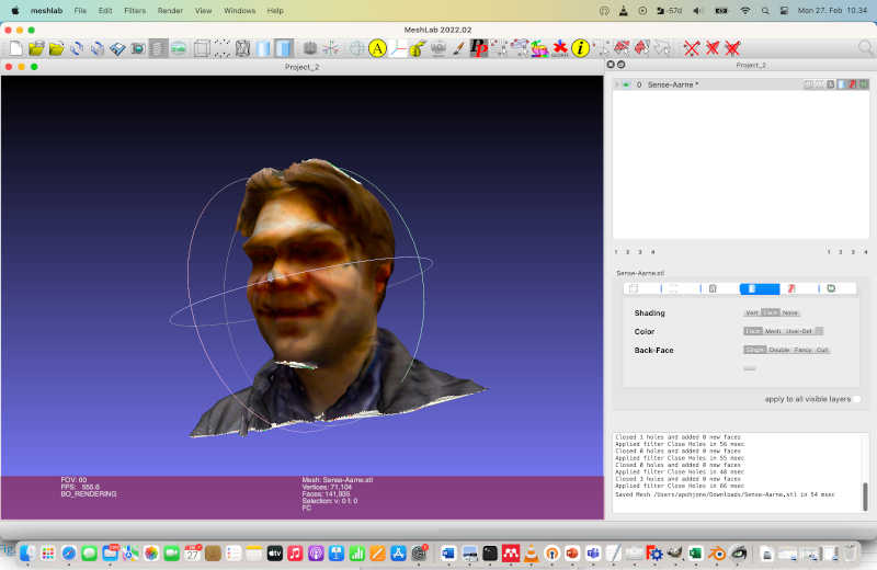
The resulting scanned file was too large for including it to the Fab Academy site.
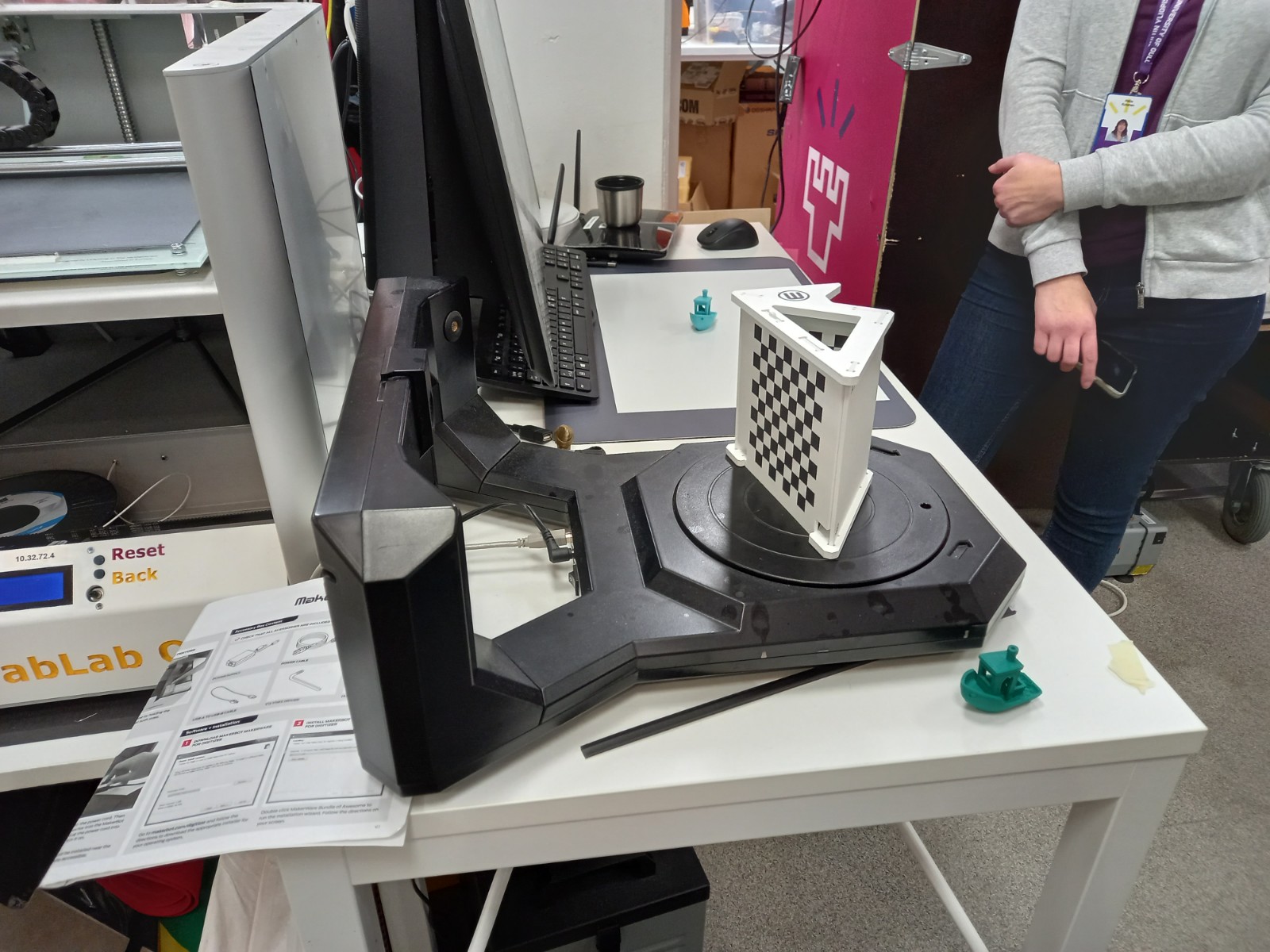
After this, I tried another tabletop 3D scanner available in our lab (MakerBot Digitizer), which had rotating plate in front of it.
The scanner was first calibrated using a specifically designed test object. The instructions were shown on the screen and the procedure was quite straightforward.
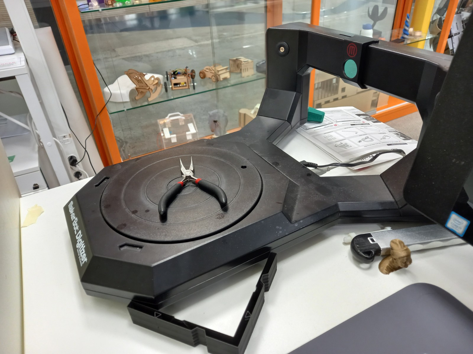
After calibration I tried to scan pliers. This was not very succesful, I think the pliers were too small in the vertical direction, and were not probably distinguishable from the plate.
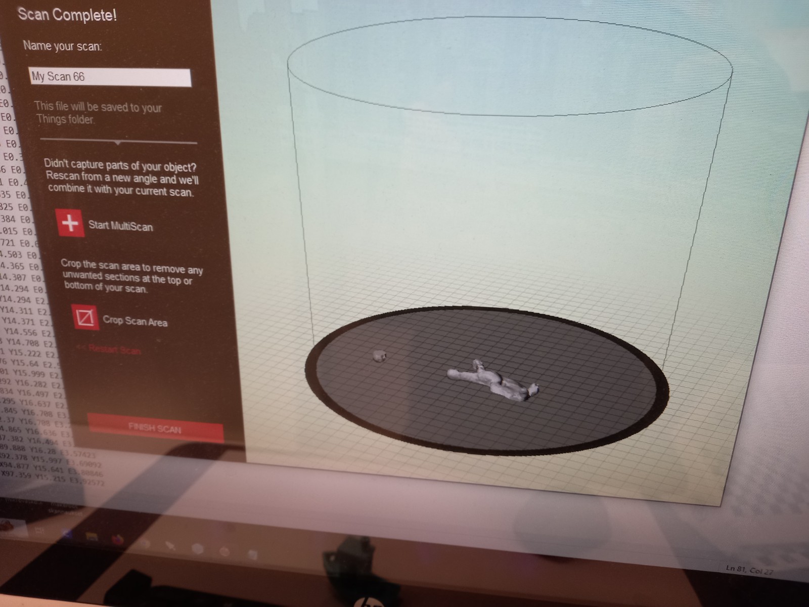
Then I tried to scan a car that had been laser cut from cardboard. This resulted in much better outcome.
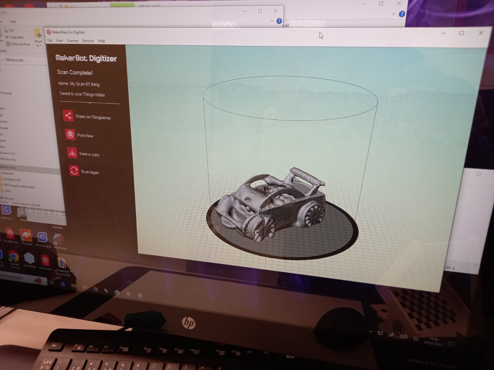
The resulting scanned file was too large for including it to the Fab Academy site.
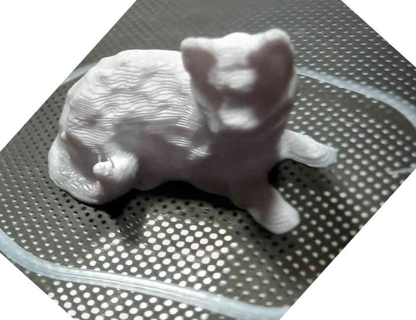
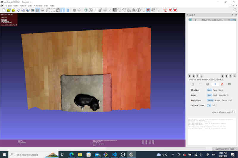
Finally, I tried photogrammetry using WIDAR app. I put a statue of a cat on a pillow and used the app to take photos from it from all sides. The result was in my opinion quite good.
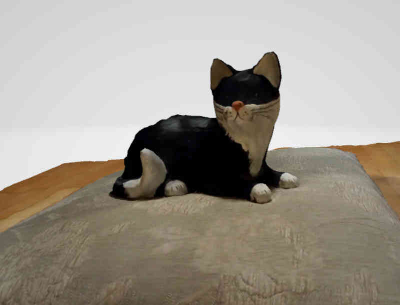
I opened the resulting file with Meshlab, and removed unnecessary regions from the scan.
Finally I exported the cat with a small layer below it to a .stl file, so that it could be 3D printed.
3D printing
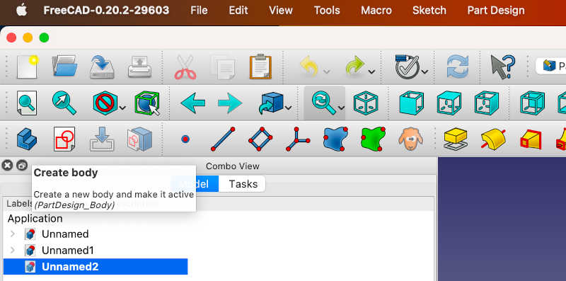
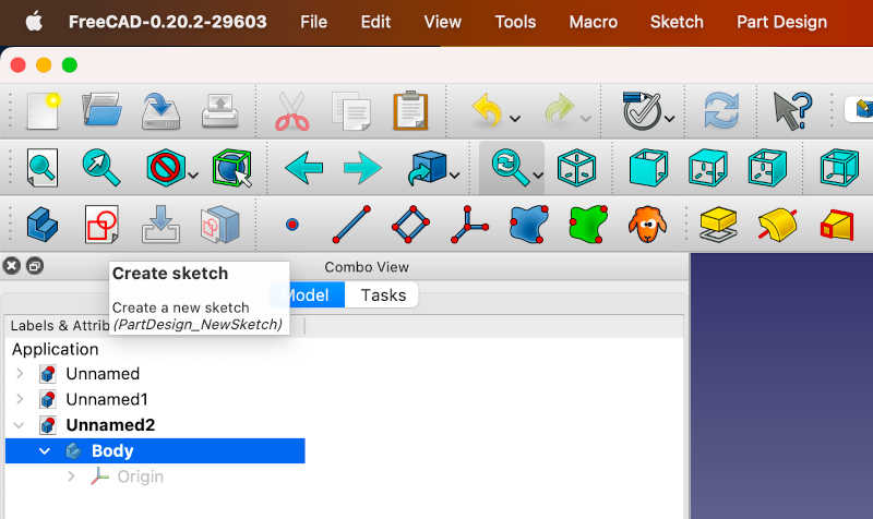
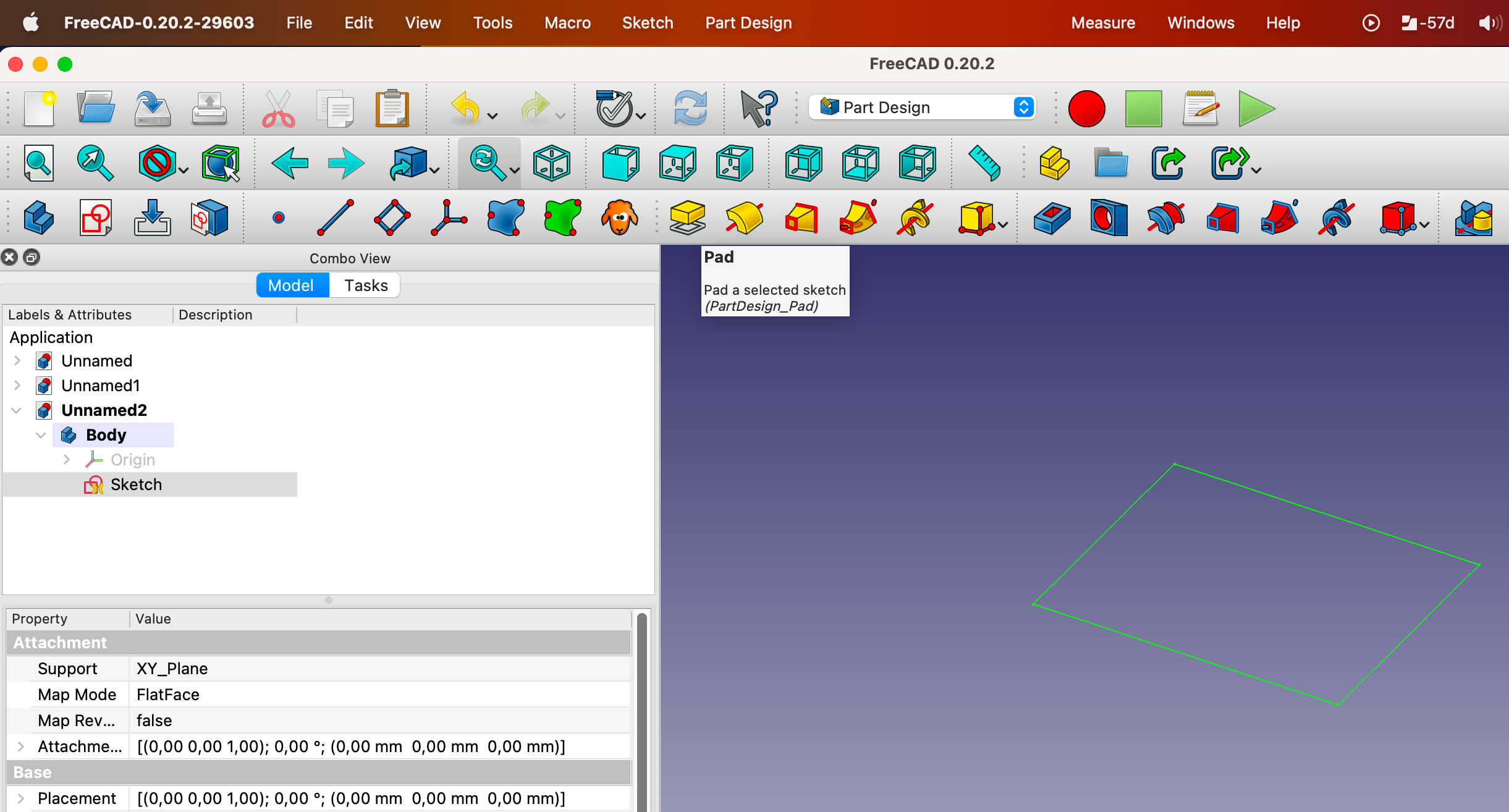
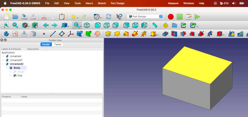
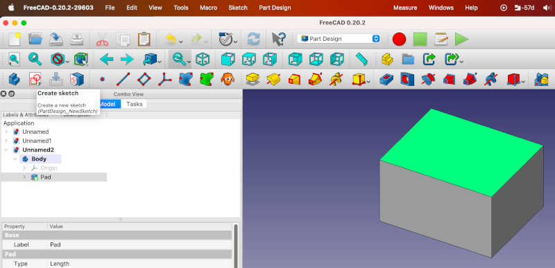
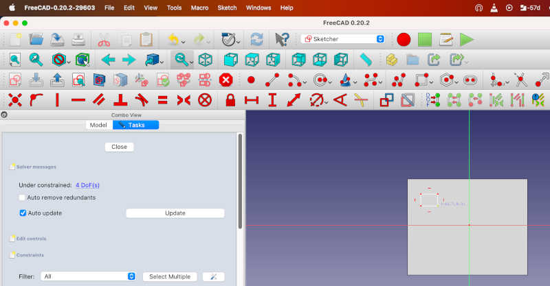
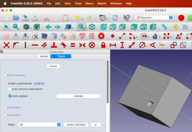
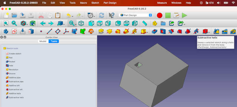
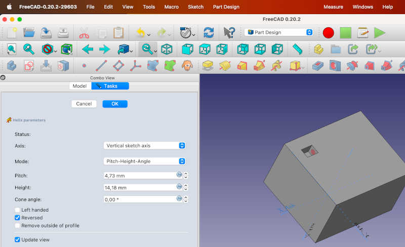
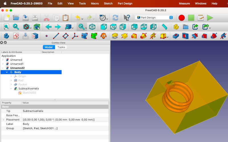
For the 3D printing we needed to print something that cannot be easily created subtractively. I noticed that there is a subtractive helix tool in the FreeCAD. I thought that it is probably difficult to cut such helical hole with CNC machine since the CNC cutting tools can usually only move in one direction, so I decided to print a box with a helical hole in it.
I decided to use the Creality Ender 3D printer, since there were several of them available at the time. The usage of the Ender printer was quite straightforward. First I prepared the slicing wiht Cura software. I did not need to do any changes to the slicing. I saved the sliced file to a memory card and inserted the card to the slot of the Ender printer. Then I chose my file from the menu of the printer and started printing by pushing the selector button.
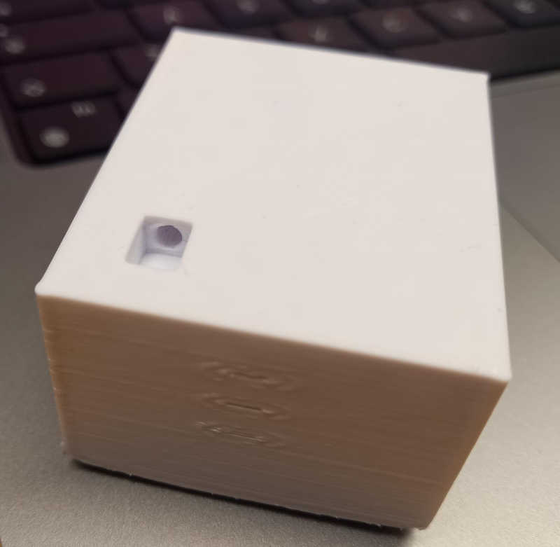
To check that the hole was open below the surface, I pushed a string to it, and pulled it out
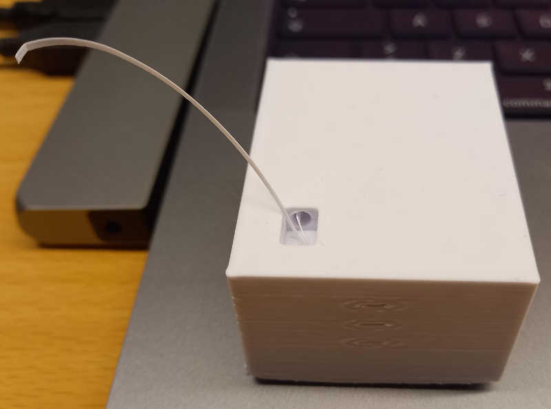
To fully confirm that the helical hole is printed and there are no fragments of support to block the tunnel, I cut the 3d printed piece in two using a saw. Then I inserted a small bendable piece of plant to the tunnel to check that it can go past.
Helical hole inside of a box, FreeCAD .FCStd file
Helical hole inside of a box, .stl file
Additionally, I wanted to also try printing the cat statue that I had scanned. It turned out that it was not a good idea to leave square area below the cat figure, since the square area was not printed ok. I had to lower the figure so that there was nothing below the cat figure and do another print. The result of the second print turned out quite fine.