My Final Project documentation
This is where I will start defining my final project idea and start to get use to the documentation process.
During week 1, I had many ideas for the final project, but for now, I am thinking to focus on the following:
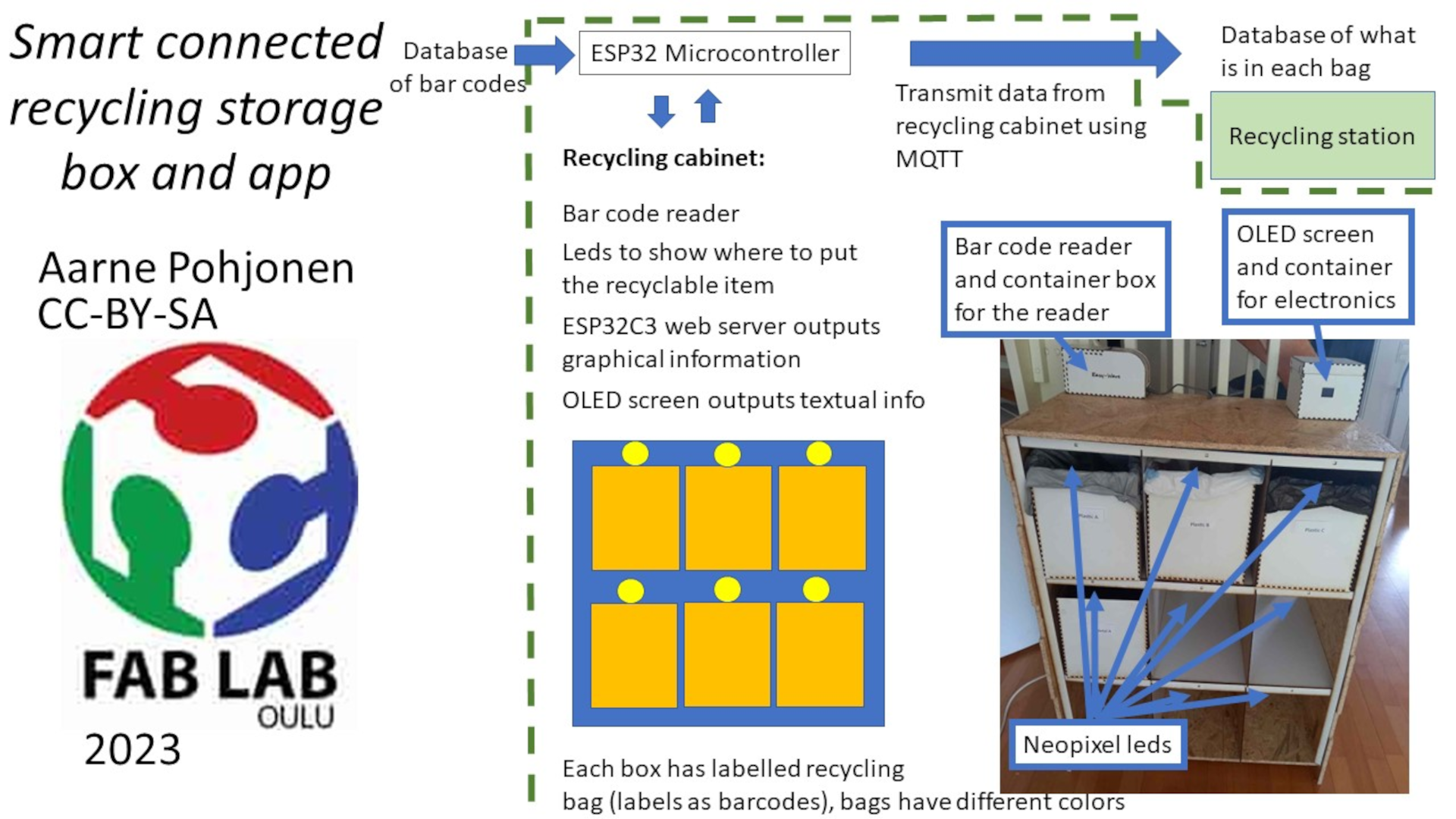
Smart connected recycling storage box and app
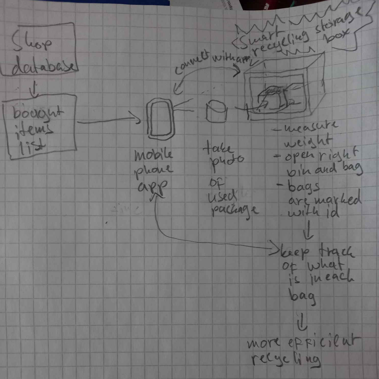
The smart recycling box and a mobile phone app make up a system that connects the list of bought itemst to identified recycling bags. The mobile phone app is used for connecting to shop database, and taking photos of the used packages. The mobile phone can also be used as bar code reader, to identify the used food or plastic package, or used item.
The recycling box opens correct bags for the package or recyclable item or indicates the user in which bag to put the used package. The recycling box also labels and identifies the bag with id number or qr code or bar code.
The bag id number or qr code will be transmitted to an information database, which is reachable by the recycling senter.
This way it is kept track what exactly is in each bag. This will make recycling much more efficient, since the different plastics can be sorted to different bags, and the information of what exactly is in each bag will be carried to the recycling station. Also different kind of electronic waste will be sorted similarly and efficiently recycled.
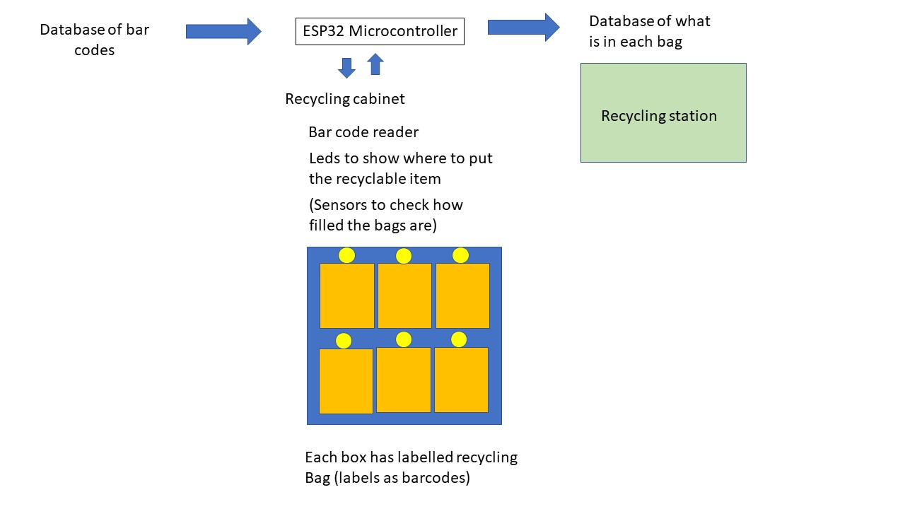
I narrowed the final project in order to be able to complete it within Fab Academy. I will not develop the mobile phone app for now, but I will use ESP 32 to read the bar code information from external database and transmit it to the other database that could be read by the recycling center. Also, in the first iteration, only the barcode reader will be used as an input device to identify products. This way I think the project is doable within the remaining Fab Academy time. In the second iteration I could add sensors to detect how much there is in each bag, then add mobile phone app, etc… if there is time.
The smart recycling box will be used by households. Similar concept can be extended to industrial and company usage.
Previous work done by others
When I started looking information on the similar previous projects, I found that Mennatallah Moustapha had previously built a very nice recycling storage device. In the fab academy pages, there was an idea for a final project for automatic recycling by Fabio Pelicano. My device extends these ideas by using databases to receive information on the bar codes to use it for accurate sorting, and transmitting the exact information on what is in each bag to the recycling center.
I also found an article on an internet publication referring a talk of Prof. Gershenfeld on a topic of including information on electronic products for achieving efficient recycling, which is a bit similar, in the sense that the information is transported alongside with the waste, to allow for efficient recycling. My device uses a bit similar concept of transferring the information, but it is managed by using the bar codes and labelling the recycling bags.
In a published peer reviewed article, it was discussed “that waste sorting capacity is driven by environmental attitudes, perceived convenience, social norms and economic drivers”. The current planned device could aid in the convenience. Also economic drivers could be introduced in the sorting, since the device keeps track on how much waste is being recycled. It would be possible to give refund based on the recycling activity, since the recycling bags are labelled and it is possible to keep track on how much people recycle, and also to check that the bag actually contains the recycled things when they arrive to the recycling station.
Computer aided design of the structures
During computer controlled machining week I had designed and milled a cabinet that I could use as a basis for the final project. The CAD design for the structures of the cabinet is shown below.
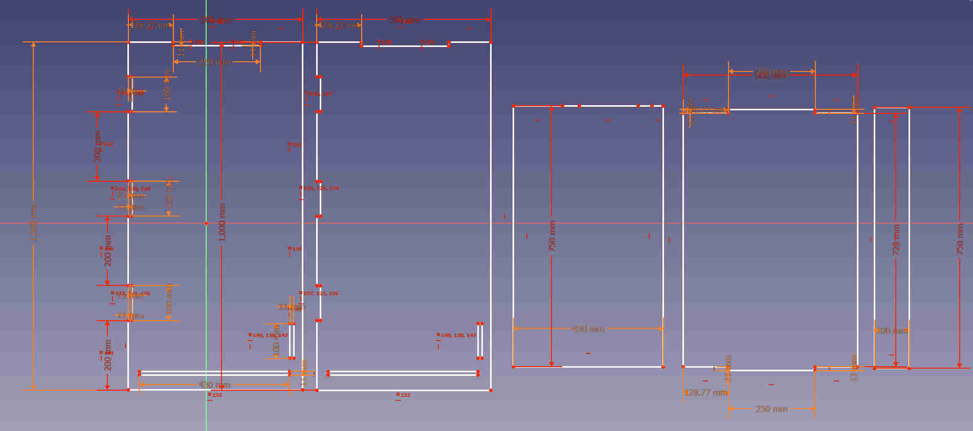
The FreeCAD files for the outer parts of the cabinet are here. The corresponding svg images are here.
I designed interior parts for the cabinet that would act as shelves and a support for the shelves.
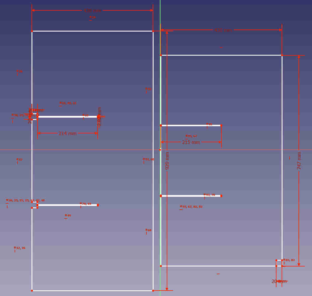
The FreeCAD files for the interior parts of the cabinet are here and the corresponding svg images are here.
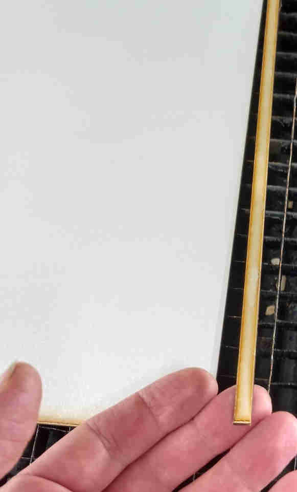
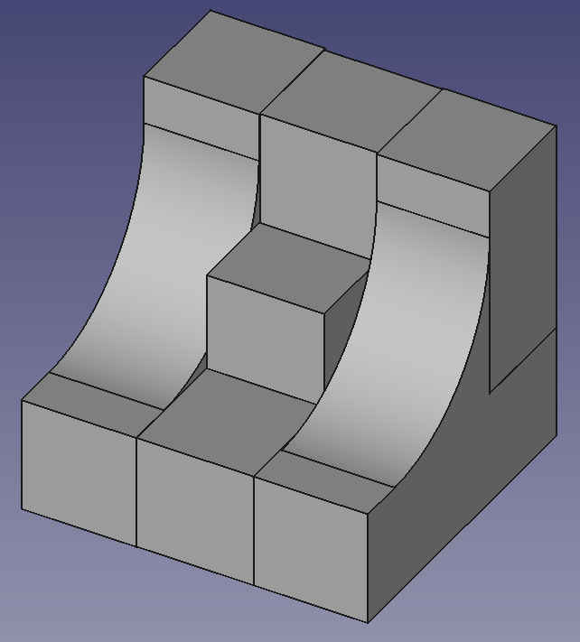
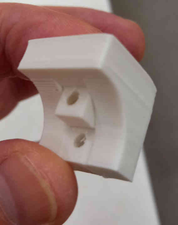
To hold the milled parts in place, I designed a simple holder piece that I could 3d print.
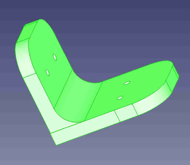
The FreeCAD file for the holder piece is here.
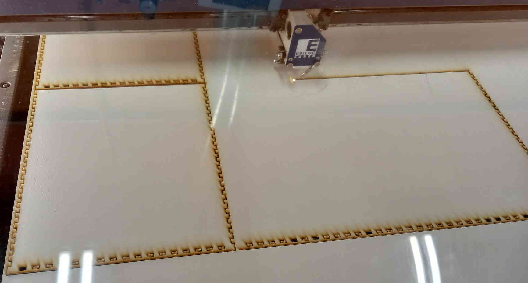
Laser cutting the interior parts of the cabinet
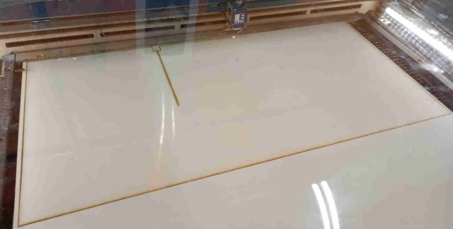
I started to laser cut the interior parts.
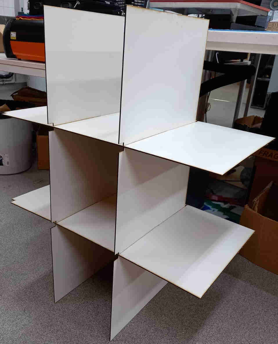
After cutting the interior parts, I assembled them
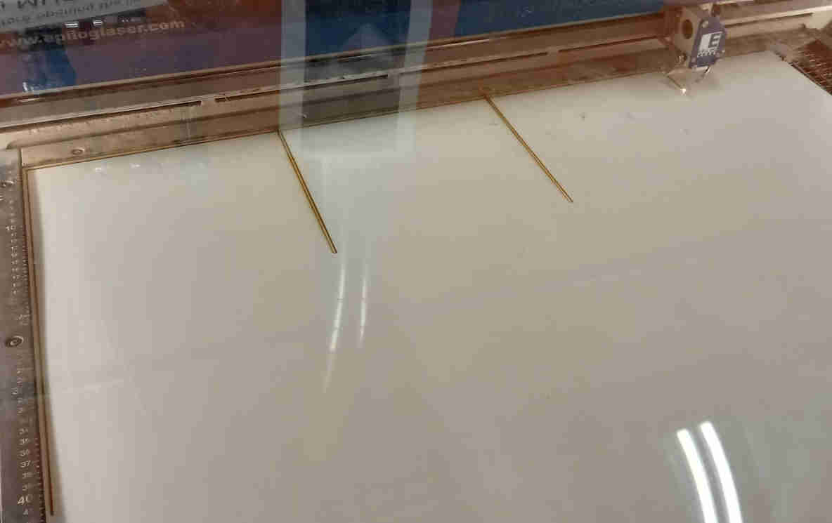
After assembly, I tried to insert the parts in to the outer structure of the cabinet. Unfortunately, the horizontal shelves were about 1 cm too wide and could not fit in side the outer part of the cabinet. For this reason, I disassembled the interior parts and laser cut half a centimeter away from both sides of the horizontal shelves. I did this by drawing a vertical line on inkscape that was as long as the side of the designed shelf, setting the origin at desired position, and then proceeded to cut the line with the laser.
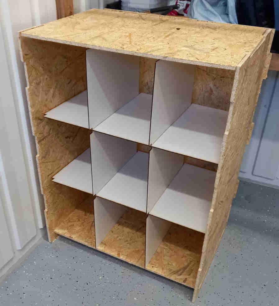
Assembly of the inner structure to the outer structure
After making the laser cuts, the inner structure could now fit inside the outer structure.
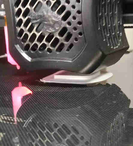
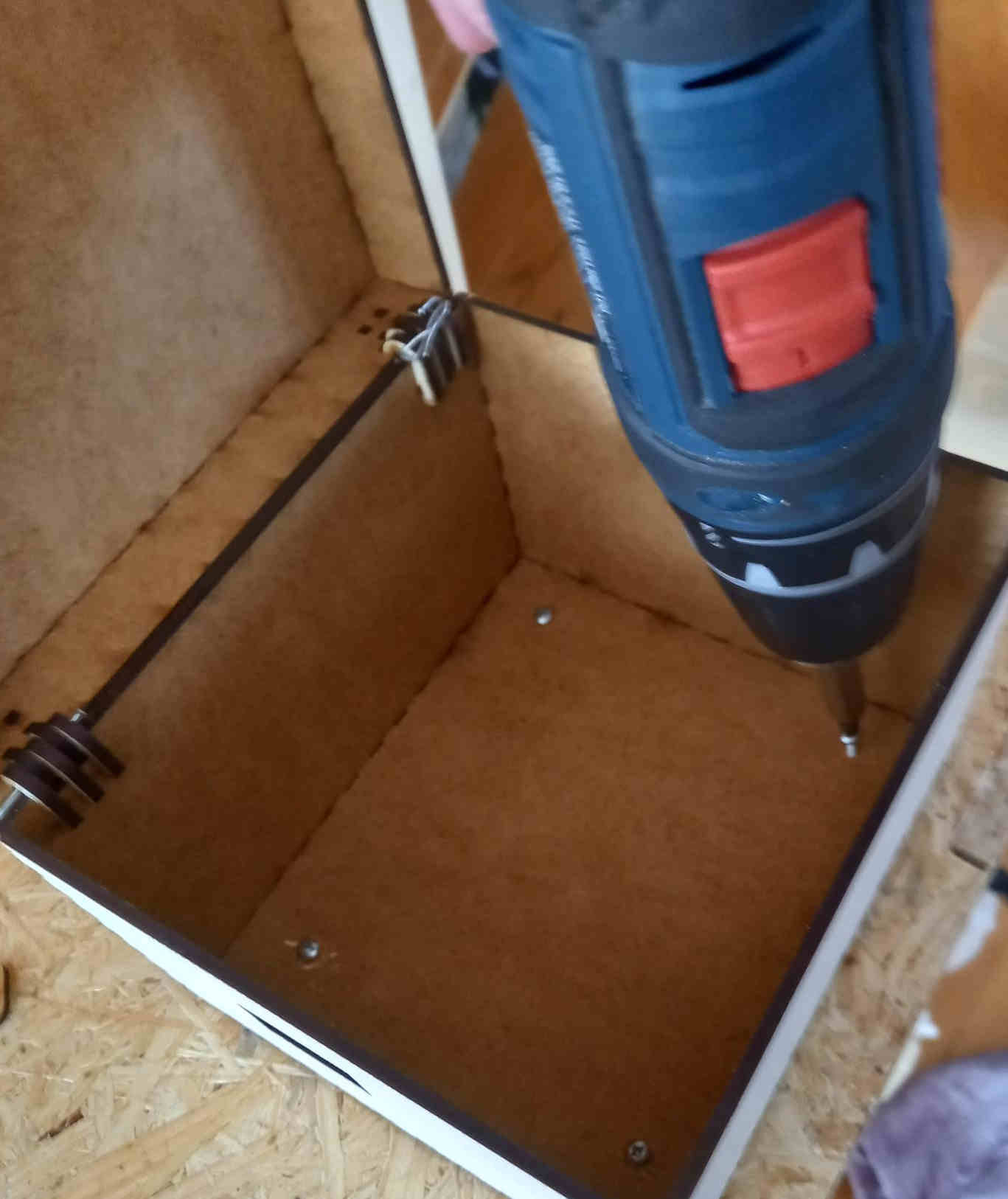
3D printing and assembling the holder pieces
After the structures were assembled, I proceeded to 3d print the holder pieces. I was going to need several of them (about 10-12), so I used several 3d printers simultaneously to get the parts ready quite rapidly in few batches.
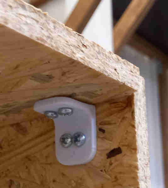
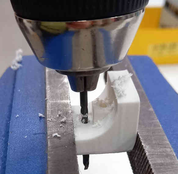
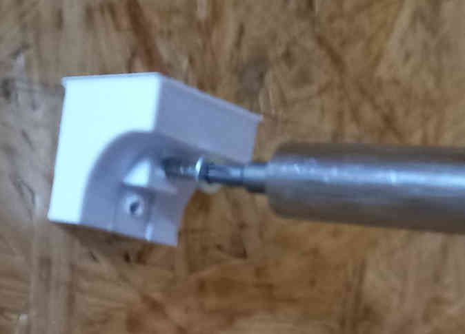
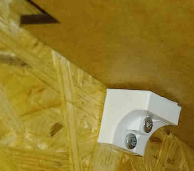
After printing the holder pieces, I drilled holes to them and assembled the to the structure with screws. I had designed too small holes to the pieces, and for this reason I needed to used the drill to make the holes larger.
While assembling the holder pieces, one of them was not in a good orientation. I did not bother to correct the orientation and thought that the plastic might adjust to the force of the screw. However, the screws caused them to bend and the piece was quite brittle and as a result the piece was broken. The holders needed to be in correct orientation, and could not tolerate bending by the screws.
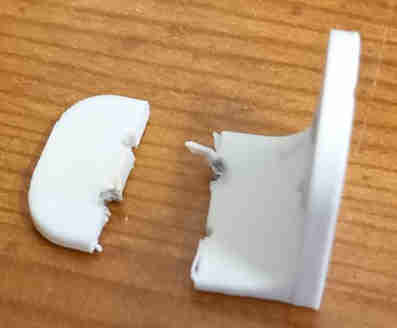
The holder pieces would not withstand much stress. The structure is designed so that there are “tooths” in the OBS board, which support the weight of the heavy boards. The 3d printed holder pieces only hold them in place, so that the boards do not slide away from their position.
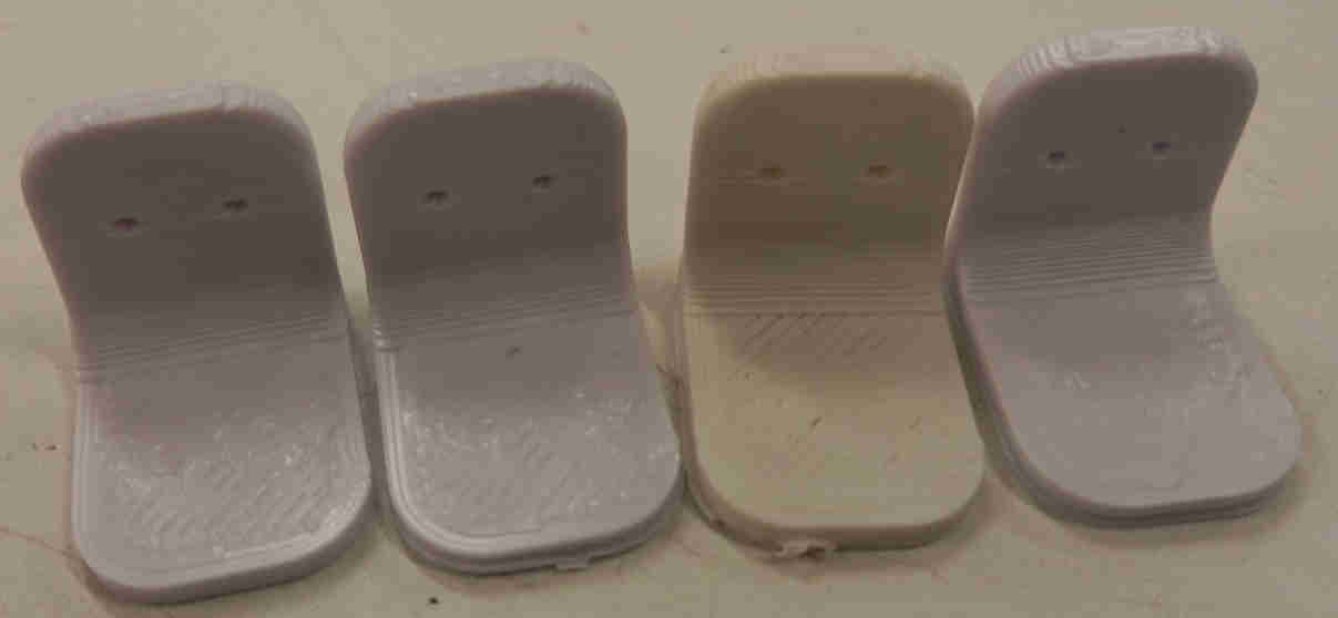
3D printing and assembly of support pieces for shelves
To support the shelves from the sides, I designed a support piece that would be attached to the cabin structure. I designed it so that I would drill holes to it and attach it with two screws.
The FreeCAD file for the support piece is here. I 3D printed 8 support pieces using Creality Ender 3D printer. I drilled two holes to each support pieces, that I would use to attach the support pieces to the walls of the cabinet with screws.
Testing the operation of the barcode scanner
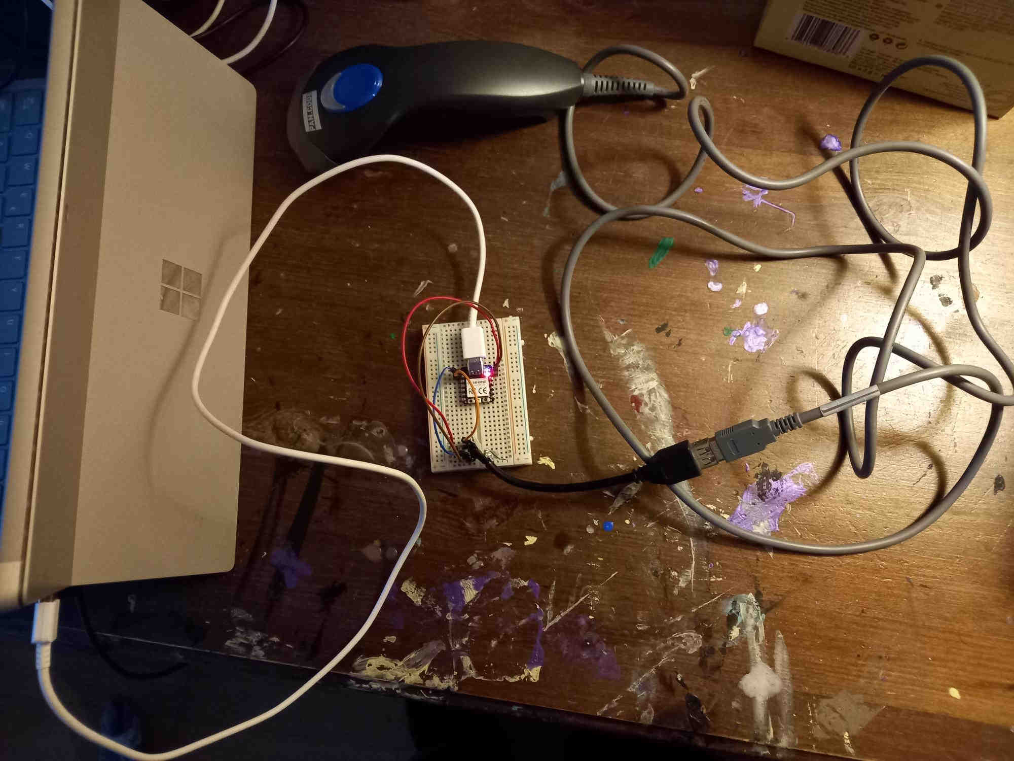
The code that I used to connect the barcode scanner to the rp2040 MCU is based on the script made by Hisashi Kato, who connected multiple usb devices to rp2040 working as usb host, pio_usb library, and the adafruit TinyUSB library. It was necessary to use version 2.02 of the TinyUSB library, and upgrading to newest version appeared to break the script.
The modified version of the code, which shows the number read by the bar code reader on the terminal is here.
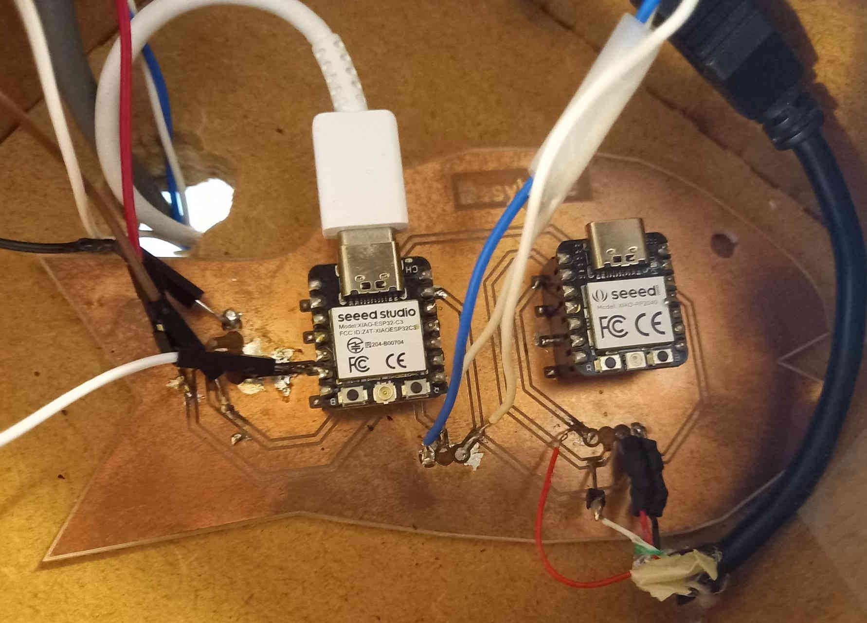
Transmitting data from RP2040 to ESP32C3 and using neopixel leds on ESP32C3
After getting the bar code reader connected to the rp2040, I wanted to transmit the data to ESP32C3 microcontroller, which we were given in the beginning of the Fab Academy. The ESP32C3 has many attractive features that I could use in the final project: the MQTT system would allow he connectivity to databases, and the web base hosted by the MCU could be used to instruct the user in more detail in the case that the disposed product has many different parts that would be disassembled before putting the parts in different recycling bags.
I thought that it would be almost trivial to connect the ESP32C3 MCU to the RP2040 using UART or I2C, with ready made libraries. However, when I tried these, it appeared that using the USB connectivity script has taken up the additional serial UART connection, and it cannot be used. Also, when I tried to use the I2C library, it appered to either break the USB connectivity, or the I2C library would not work - I was not able to get them both working at the same time.
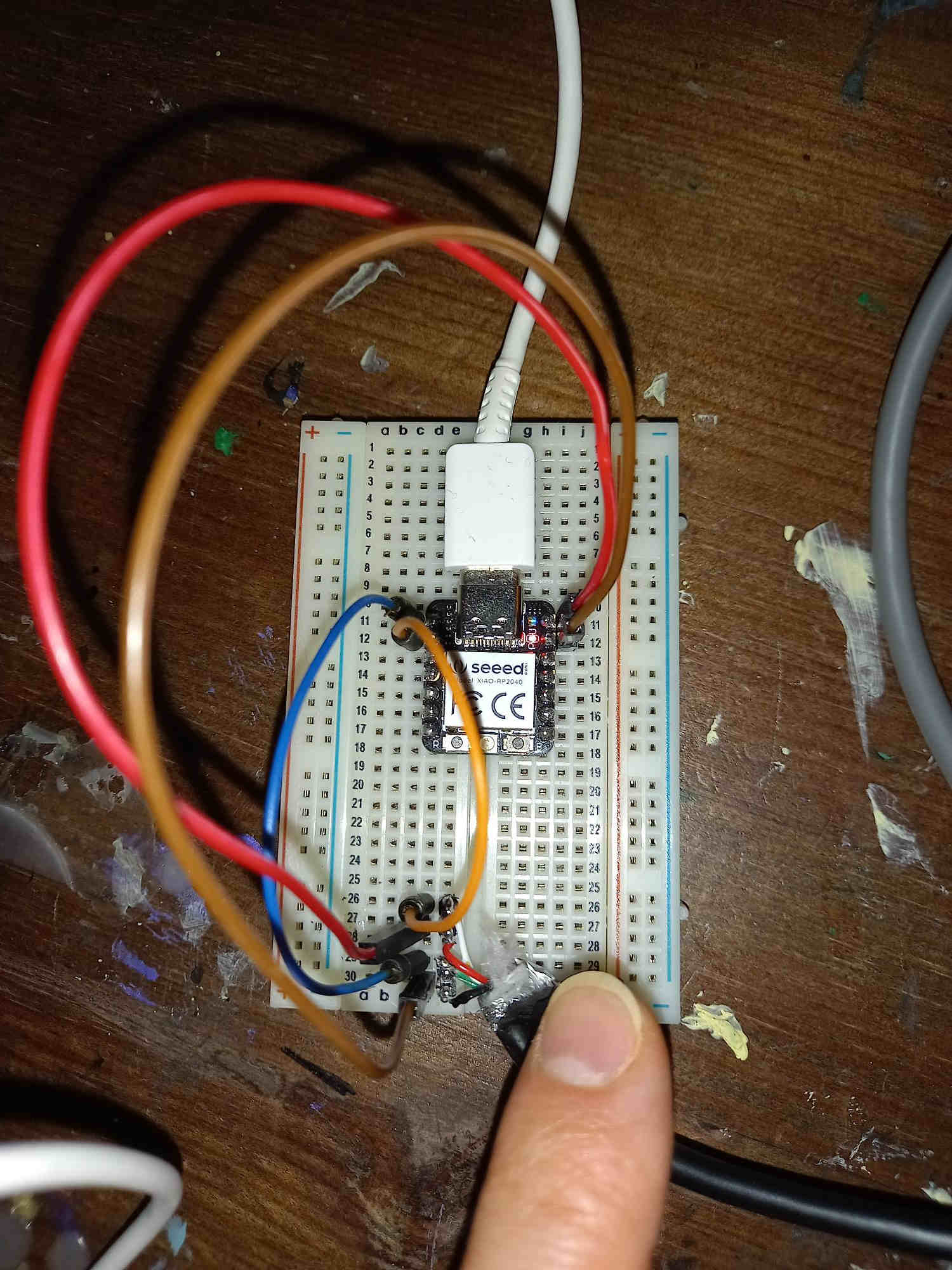
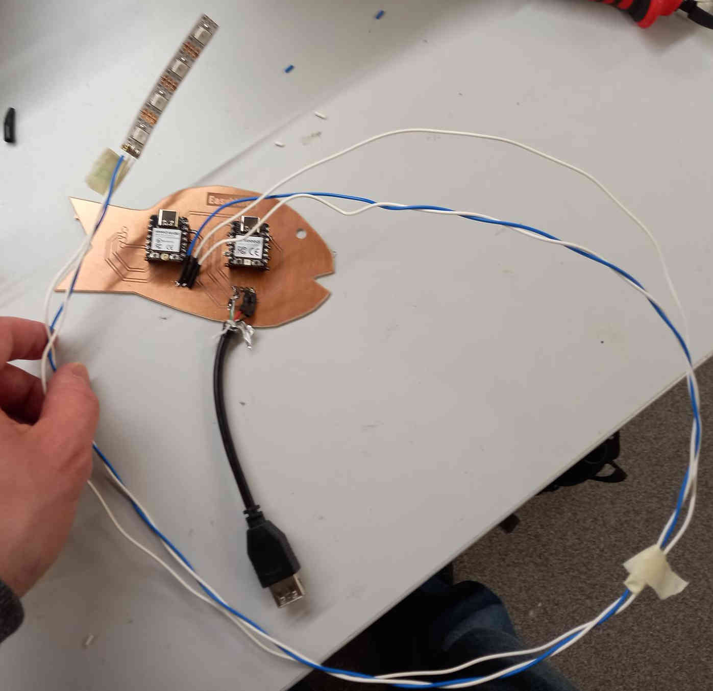
As a final resort, I decided program my own simple quick and dirty protocol (I will call it hacktocol;) for transmitting the data from RP2040 to ESP32C3. I connected data pin of RP2040 to the data pin of ESP32C3 and I also connected the grounds. Then I made a simple data transfer protocol. I only wanted to transmit sequence of numbers from 0 to 9 (the barcode) with the protocol, so I chose to use 4 bit representation of the integers, sequence 1111 for starting the communication and 0000 for ending. I represented 0 with bit sequence 1010:
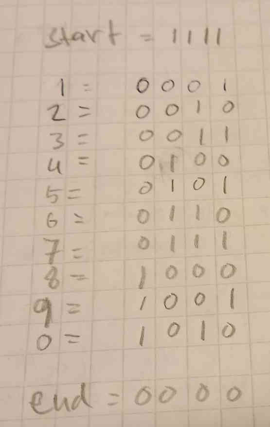
The code that I used to transmit data from RP2040 to ESP32C3 is here.
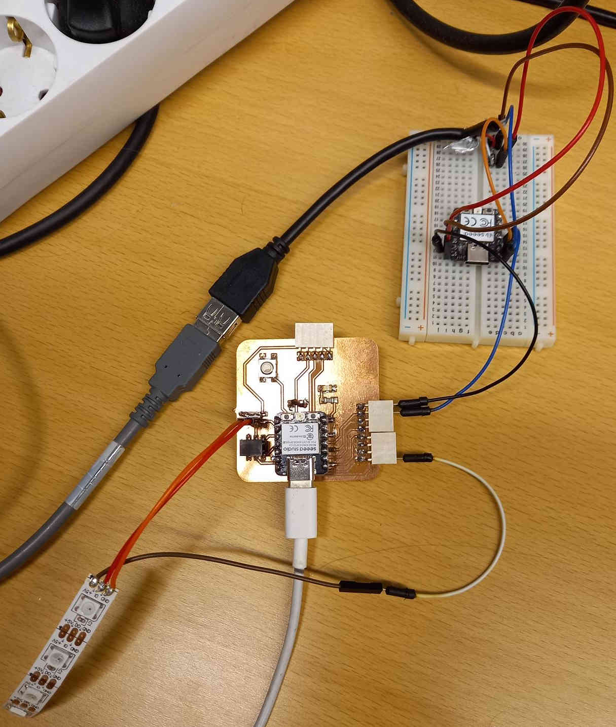
Once I got the data transmitted to the ESP32C3 from the RP2040 (which handled the connection to the barcode reader with USB), I connected neopixel led strip to the ESP32C3, and programmed it to indicate different leds depending on which barcode was read. In the first test I used the first led to light up when one bar code was read, and 3rd and 4th led to light up when another barcode was read (some products can be made up of different materials, which need to be deposited to different recycling bags).
The Arduino code on EP32C3 that I used to receive the communication from rp2040 and light up the leds according to the received barcode is here.
Adding OLED screen to the project
I also added an OLED screen to the project, as I wanted to be able to give textual information to the user. I also had an idea that I could use ESP32C2 to provide a web server that could be used for instructing the user in graphical way, and the OLED screen could show the address of the web server, so that mobile phone could connect to it using the browser. I connected the OLED screen in the same way as I did in the output devices week.

Designing electronics and circuit board
I designed electronics in the same way as I did in the electronics design week. First I did the schematics, where I reproduced the connections that I had on the breadboard. Then I routed the wires and designed the PCB.
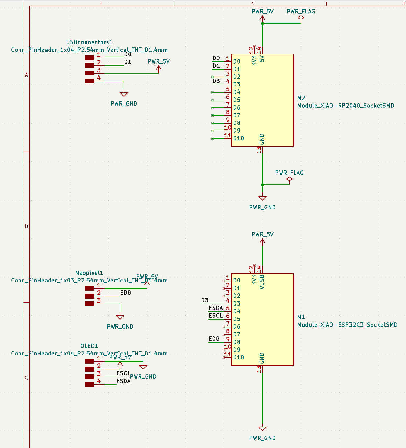
The schematics file designed with KiCAD is here.
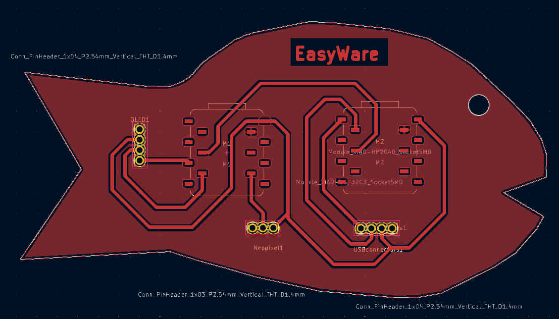
The PCB designed with KiCAD is here.
Final assembly and basic operation
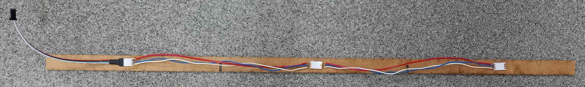
To complete the project packaging, I used laser cutter to cut enclosures for the electronics and the wires.
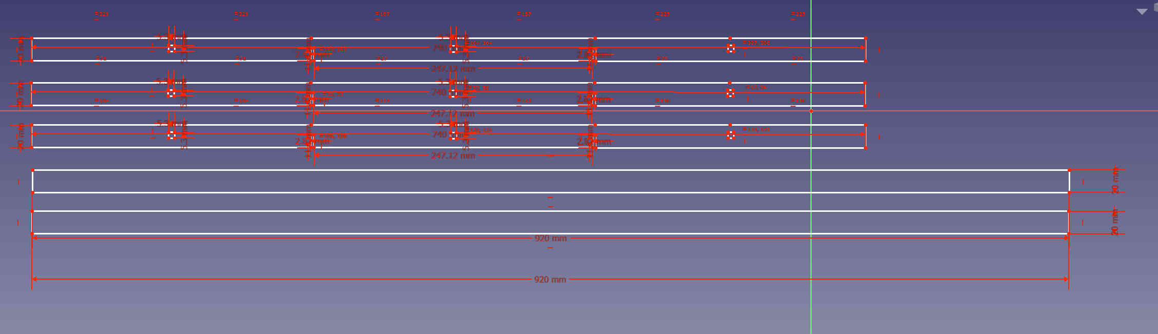
The FreeCAD files for the strips are here. The svg files for the strips are here.
I used the website https://festi.info/boxes.py/ to design hinged enclosure box for the electronics, a breadbox type of box with flexure as a container for the barcode reader and the boxes for the recycling bags. I used the value 0.06 for the burn (the burn value issimilar to kerf), which yielded good snap fit. I used inkscape to change the line width to 0.02 for cutted parts, remove unnecessary text and add my tag for the project. The design files: for the hinged box, the barcode holder, and the container box for the bags part 1 and container box for the bags part 2 (I had to separately cut parts for the container box, since they did not fit to the laser cutter in vertical direction).
I had used a lot of HDF material, and the lab ran out of it. I left the final board for others to use. It is straightforward to cut the missing boxes when we get new supply of HDF boards, and the idea of the final project can be demonstrated with four boxes already.
I assembled the hinged box for electronics and the barcode container to the recycling cabinet using screws and hot glue.
I drilled a hole on the floor of the box and routed the wires, which were connected to the neopixel leds, through the hole. I had some problems with wires coming off, when I arranged the wires, and had to resolder them.
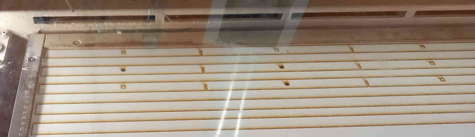
Then I assembled the laser cut HDF strips containing the neopixel leds to the recycling cabinet.
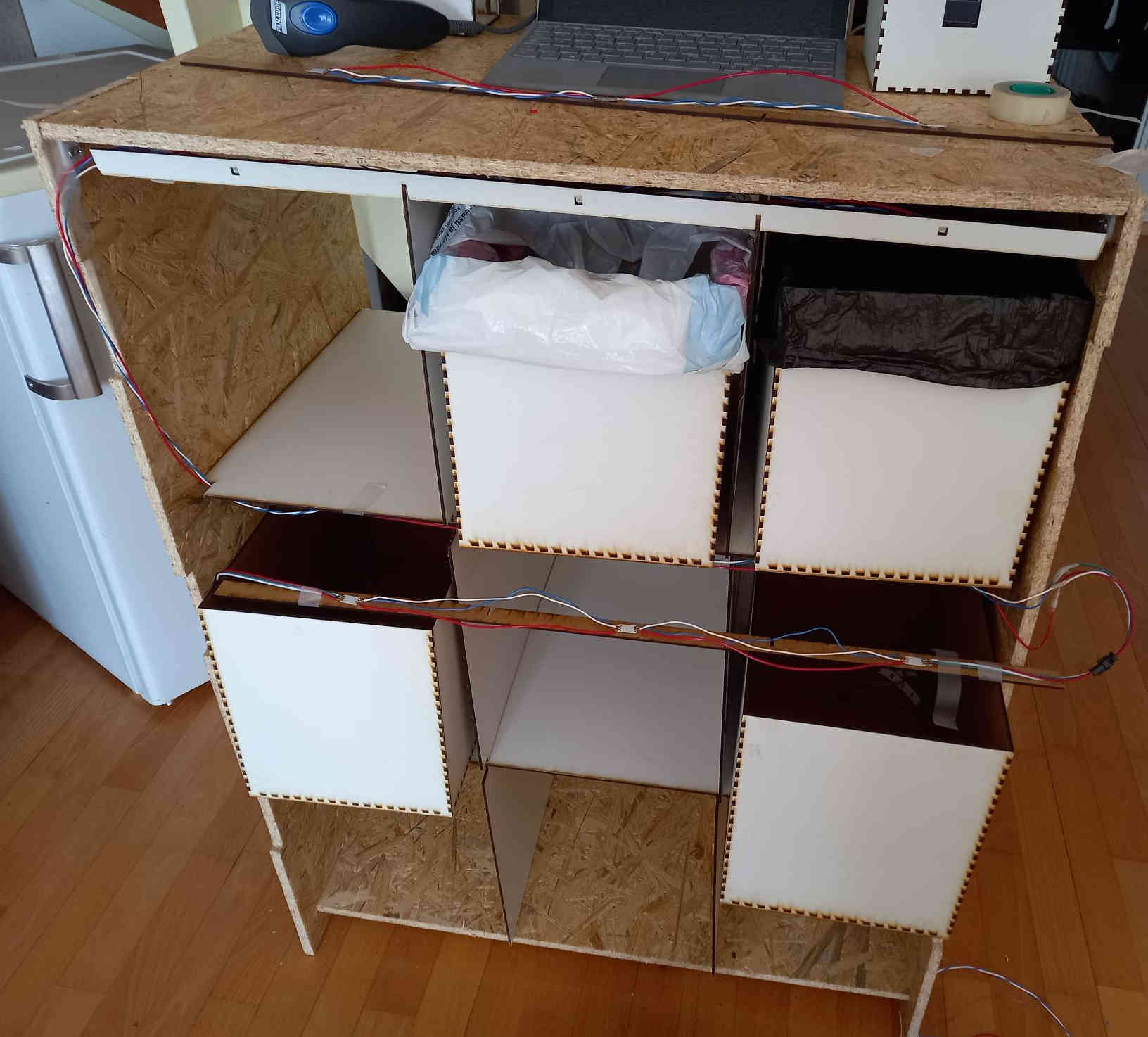
Finally I assembled the vertical laser cut strips, and then the physical construction was ready.
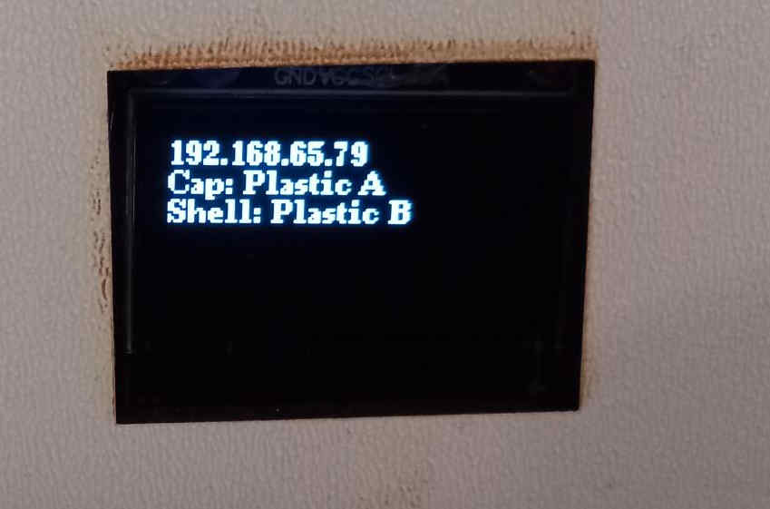
I uploaded code to the ESP32C3 MCU to test the operation of the recycling box to use neopixel leds to sort the material to different bags. In the code, also ESP32C3 also provides webhost, (which I intend to use as providing graphical instructions to user) and it needs to connect to wifi. For the code to operate, you must provide a wifi access point and modify tne code with the correct wifi access point name and password. The access point address is shown on the OLED screen.
Output using OLED and ESP web server
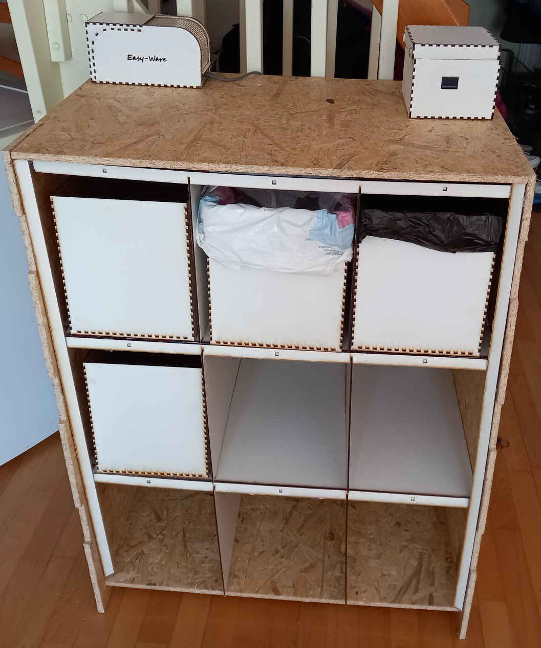
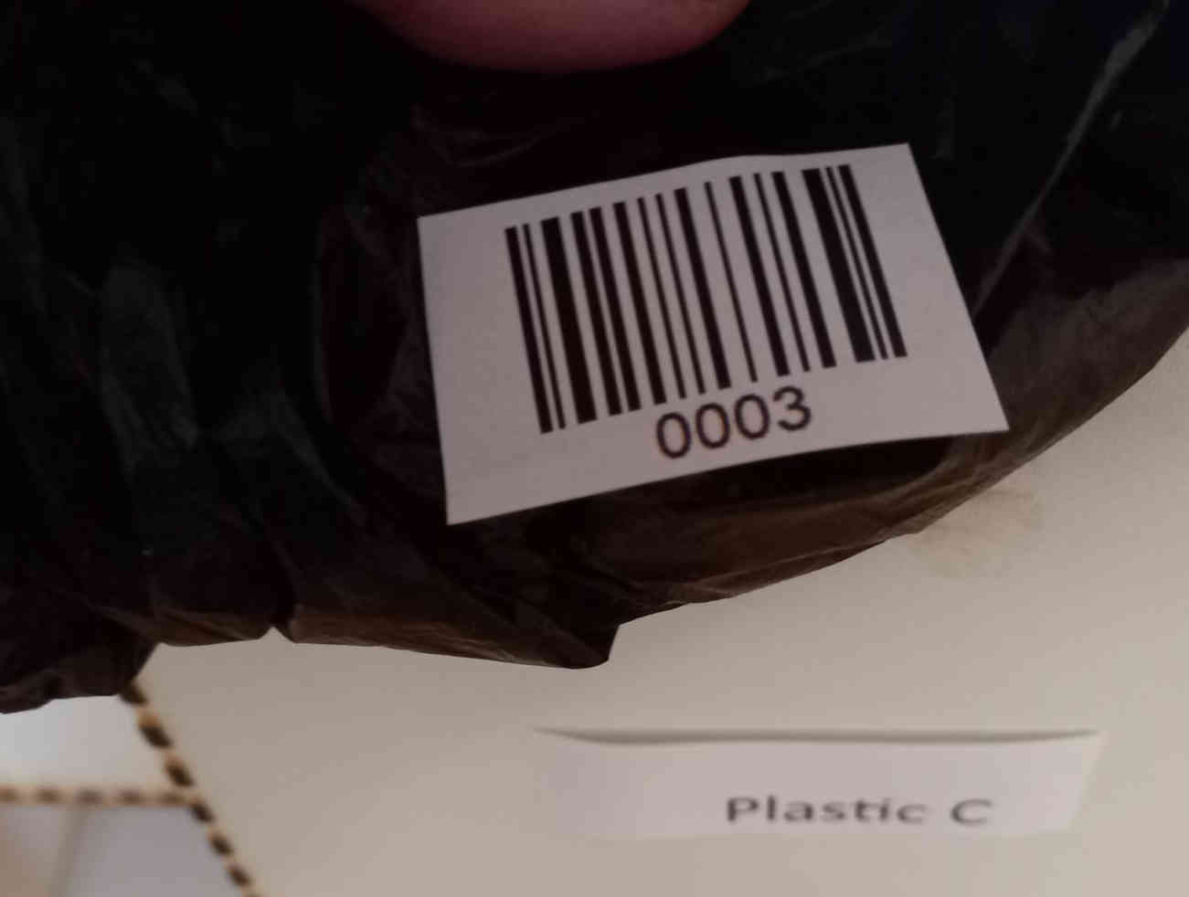
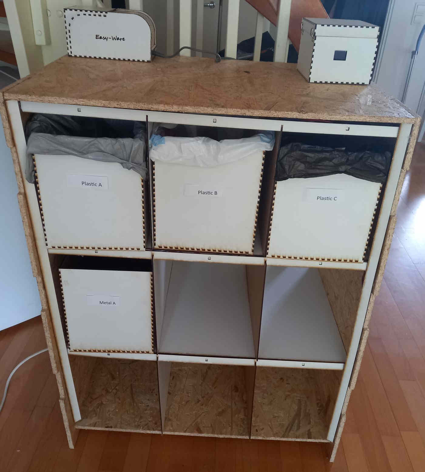
Since some packages may consists of more than one type of material, it is important to be able to instruct the user to dispose the different materials to different recycling bags. To aid in this, I labeled boxes and I used the textual output on the OLED screen to instruct the user to put the different packaging materials in to correct bags.
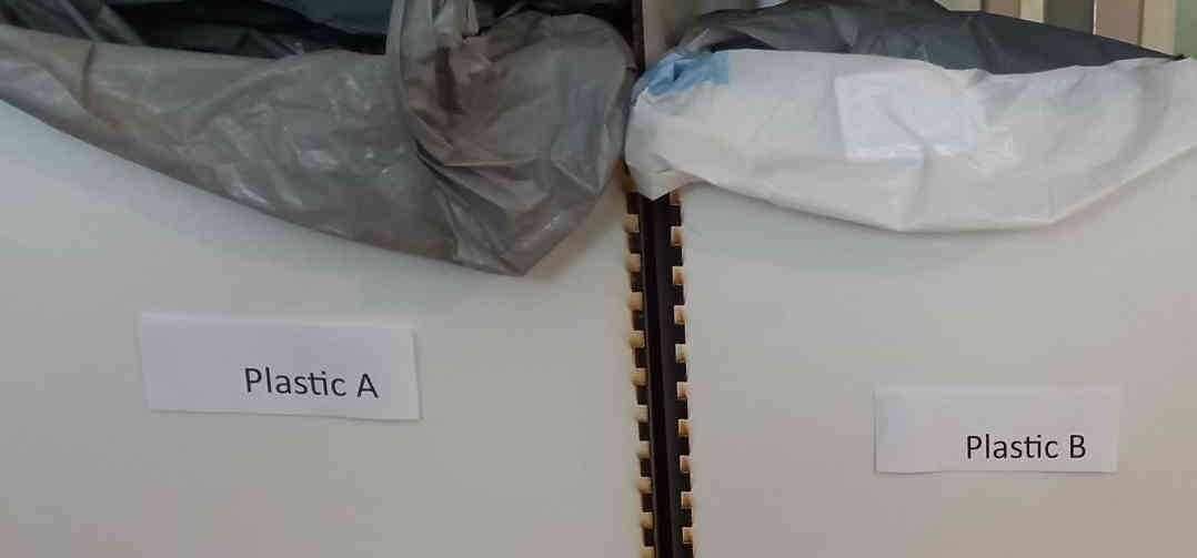
The recycling bags have different colors, so it would be easy to distinguish the types of bags. To allow for more accurate recycling, the bags are labeled with barcodes. This would allow keeping exactly track of what packaging material is in each bag.
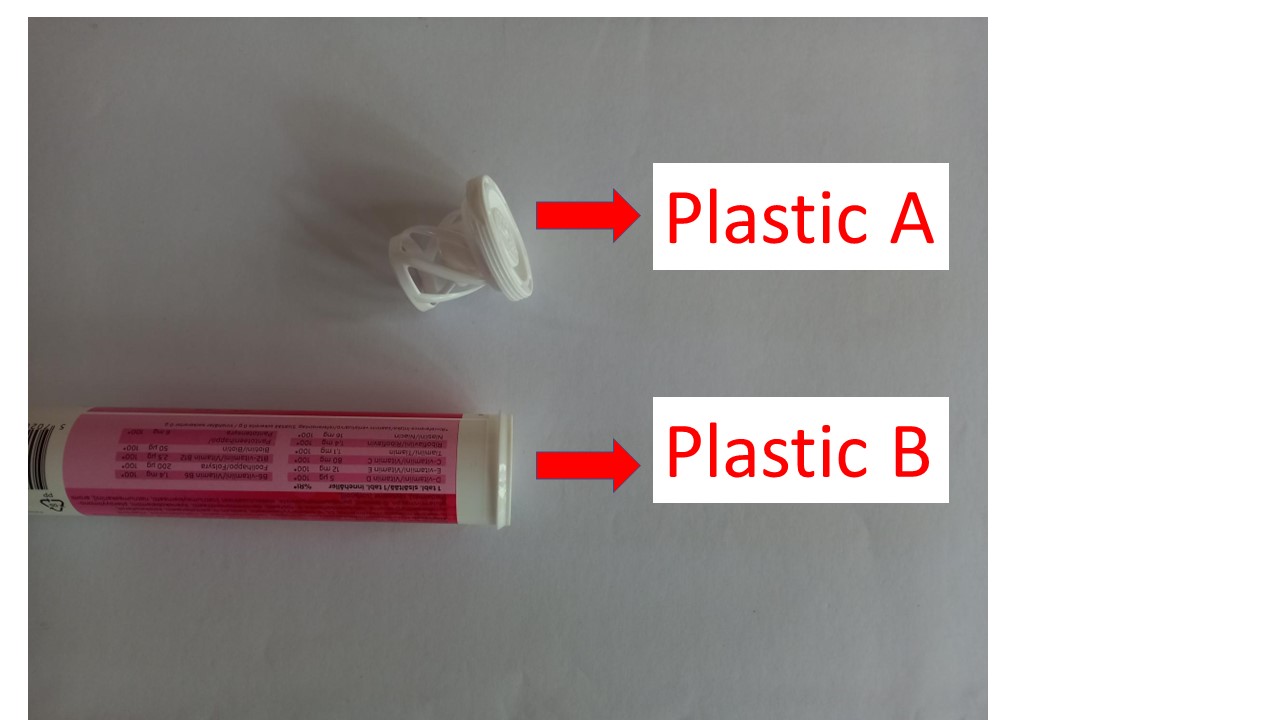
To be able to give more information to the user, including graphical instruction, I used the web server capability of the ESP32C3 MCU in the similar way as I had done during Interface and Application Programming week. I modified the code so that once the bar code of the package has been read, the web server shows an image, which instructs the user to dispose the parts of the packages to correct bags. I used the following kind of images to instruct the user.
The operation of the web server instruction is shown in the final project presentation video.
The code on the ESP32C3 for this development stage is here. This may be the final development stage for Fab Academy, but I will still try to incorporate MQTT connectivity, if there is enough time.
The recycling cabinet with the labels is shown here
Establishing MQTT connection from ESP32C3 to Raspberry Pi computer over network
The final goal of the project was to transmit data from the recycling cabinet to external computer over network, so that the information of what package materials are in each bag could be transmitted to a database hosted at the recycling center (this is the vision of this project). To achieve this goal, I applied the MQTT messaging protocol to transmit the data from ESP32C3 to Mosquitto program, which was hosted at a Raspberry Pi computer (model 3B). I used the PubSubClient library by Nick O’Leary on the ESP32C3.
Both the ESP32C3 and the Raspberry Pi computer were connected to the same wireless network, which was provided by a WiFi access point that I had set up on my mobile phone.
To install the the Mosquitto MQTT broker on a Raspberry Pi computer, I followed the Random Nerd tutorial, which gives good instructions for this. The key steps from the tutorial are:
Install the Mosquitto Broker:
sudo apt install -y mosquitto mosquitto-clients
Enable the Mosquitto to automatically start when the Raspberry Pi boots:
sudo systemctl enable mosquitto.service
Enable remote access (no authentication) Edit /etc/mosquitto/mosquitto.conf file and add the lines
listener 1883
allow_anonymous true
Restart the Mosquitto, so that the changes take effect
sudo systemctl restart mosquitto
Receiving MQTT messages is described as a part of another Random Nerd tutorial: To start receiving messages on topic named testTopic, the following command is used on the Raspberry Pi computer terminal:
mosquitto_sub -d -t testTopic
(it is noted that the tutorial also describes how to send messages).
The hostname of the Raspberry Pi is needed, so that the ESP32C3 can send messages to the broker. This can be found by typing
hostname -I
on the Raspberry Pi terminal.
On the ESP32C3, I adapted my code according to the tutorial at digikey.com
The final code I used on the ESP32C3 to achieve the MQTT connection, in addition to the previously described web server functionality and other tasks is here. This is the final code that I used on the project within Fab Academy 2023.
The most important parts on the code related to the MQTT messaging are:
Libraries and initial definitions:
// Load Wi-Fi library
#include <WiFi.h>
#include <PubSubClient.h>
// Replace with your network credentials
const char* ssid = "Inser WiFi access point name here";
const char* password = "Insert Password here";
const char *ID = "SenderIDYouCanChangeThis";  // Name of our device, must be unique
const char *TOPIC = "testTopic";

IPAddress broker(192,168,169,4); // IP address of your MQTT broker eg. 192.168.1.50
WiFiClient wclient;
PubSubClient pclient(wclient); // Setup MQTT client
In the setup():
pclient.setServer(broker, 1883);
Function to reconnect if connection lost:
// Reconnect to client
void reconnect() {
  // Loop until we're reconnected
  while (!pclient.connected()) {
    Serial.print("Attempting MQTT connection...");
    // Attempt to connect
    if (pclient.connect(ID)) {
      Serial.println("connected");
      Serial.print("Publishing to: ");
      Serial.println(TOPIC);
      Serial.println('\n');

    } else {
      Serial.println(" try again in 5 seconds");
      // Wait 5 seconds before retrying
      delay(5000);
    }
  }
}
In the main loop, to keep up connection:
  if (!pclient.connected())  // Reconnect if connection is lost
  {
    reconnect();
  }
  pclient.loop();
And, most importantly, to send the data (bag number and the barcode) for this demo. If the bar code 6411200112600 is read (and the package is put in bag 0003):
pclient.publish(TOPIC, "0003 6411200112600");
The following video shows how the bag number (0003) and the package bar code (6411200112600) are transmitted to the Raspberry Pi computer.
Improving the aesthetics by adding a laser engraved photo
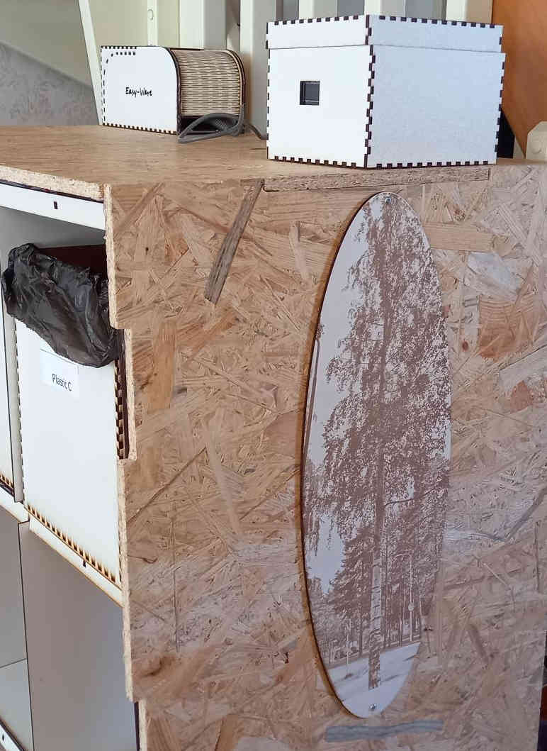
Finally, I decided to make a small enhancement to the aesthetics of the recycling cabinet. Although I did not have it in mind initially, the aestetics is important because if the cabinet is being located in the living room, it should not look too disturbing. For this reason, I used laser engraving and cutting to make an ornament on the painted HDF board, which I attached to the wall of the cabinet. I took a photo of a birch tree, cut the ellipsoid region with gimp, imported it to inkscape and in inkscape I made an ellipse shaped line edge to the image. The file that I used for cutting and engraving is here.
Final project presentation slide and video
A slide describing my final project is here:
A video presenting my final project is shown below:
Materials
| Qty | Description | Price | Link | Notes |
|---|---|---|---|---|
| 1 | OBS board | 40 euros | link | Obtained from fab lab |
| 1 | ESP 32 | 7.95 euros | link | Obtained from fab lab |
| 9 | Neopixel leds | few euros | link | from fab lab |
| 1 | barcode scanner (used) Pan Code A300 | 2.00 euros | link | used from tori.fi |
| 1 | HDF board | 20.00 euros | link | from fab lab |
| 1 | FR1 Circuit board material | 1 euro | link | from fab lab |
| 1 | OLED screen | 11 euro | link | from fab lab |
| 1 | PLA filament | 0.3 euro | link | tens of grams, obtained from fab lab |
Copyright 2023 Aarne Pohjonen. I will grant the CC-BY-SA license for the final project:
“This license allows reusers to distribute, remix, adapt, and build upon the material in any medium or format, so long as attribution is given to the creator. The license allows for commercial use. If you remix, adapt, or build upon the material, you must license the modified material under identical terms. CC BY-SA includes the following elements: BY Credit must be given to the creator SA Adaptations must be shared under the same terms”