2. Computer-Aided Design
Designing a 3D object using Autodesk Fusion
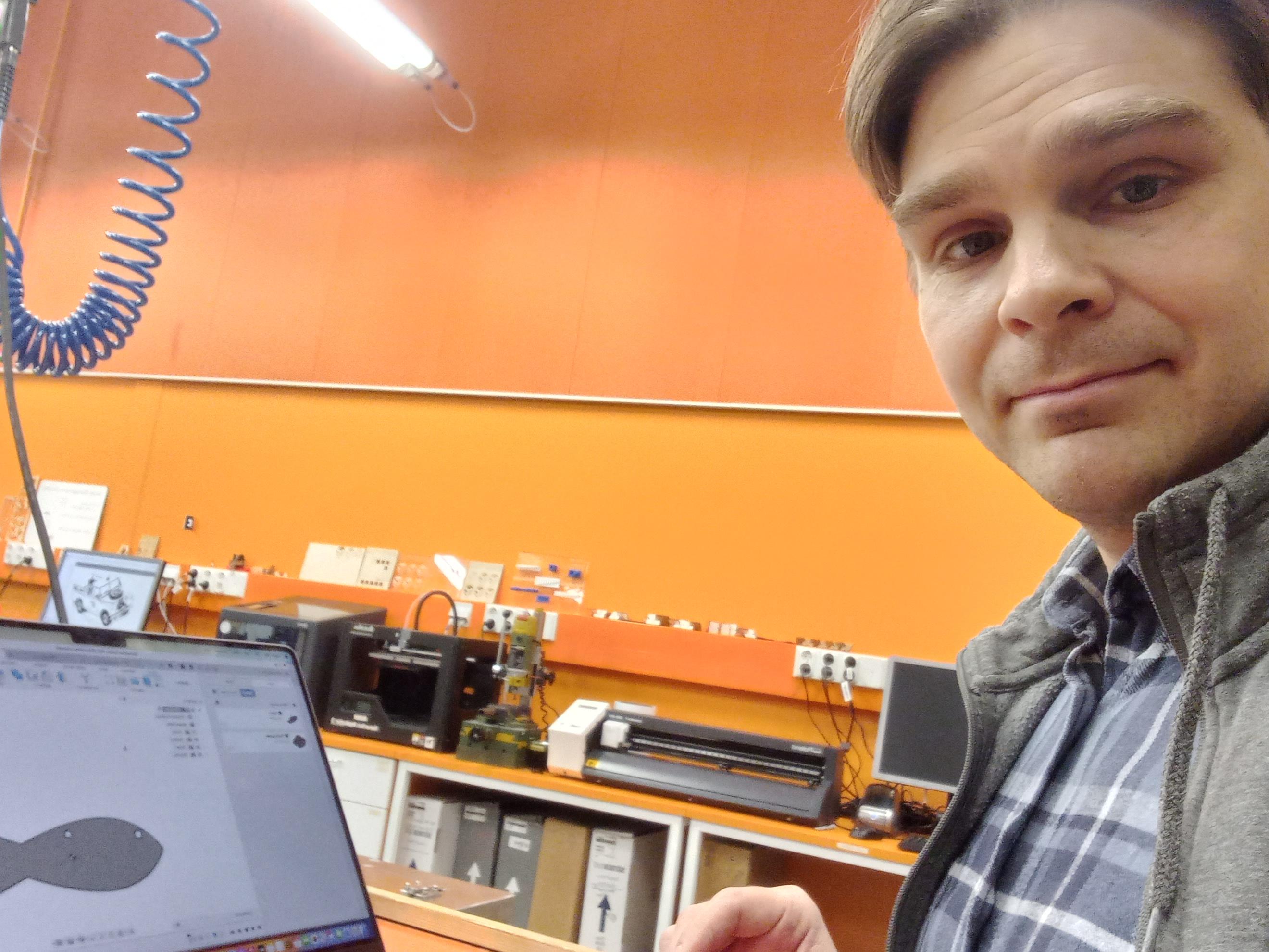
I started by testing the use of Autodesk Fusion software to design a simple object, that I could use in my final project (this design was for the old final project, I changed the final project topic later).
First I draw a sketch with polyline and line tools.
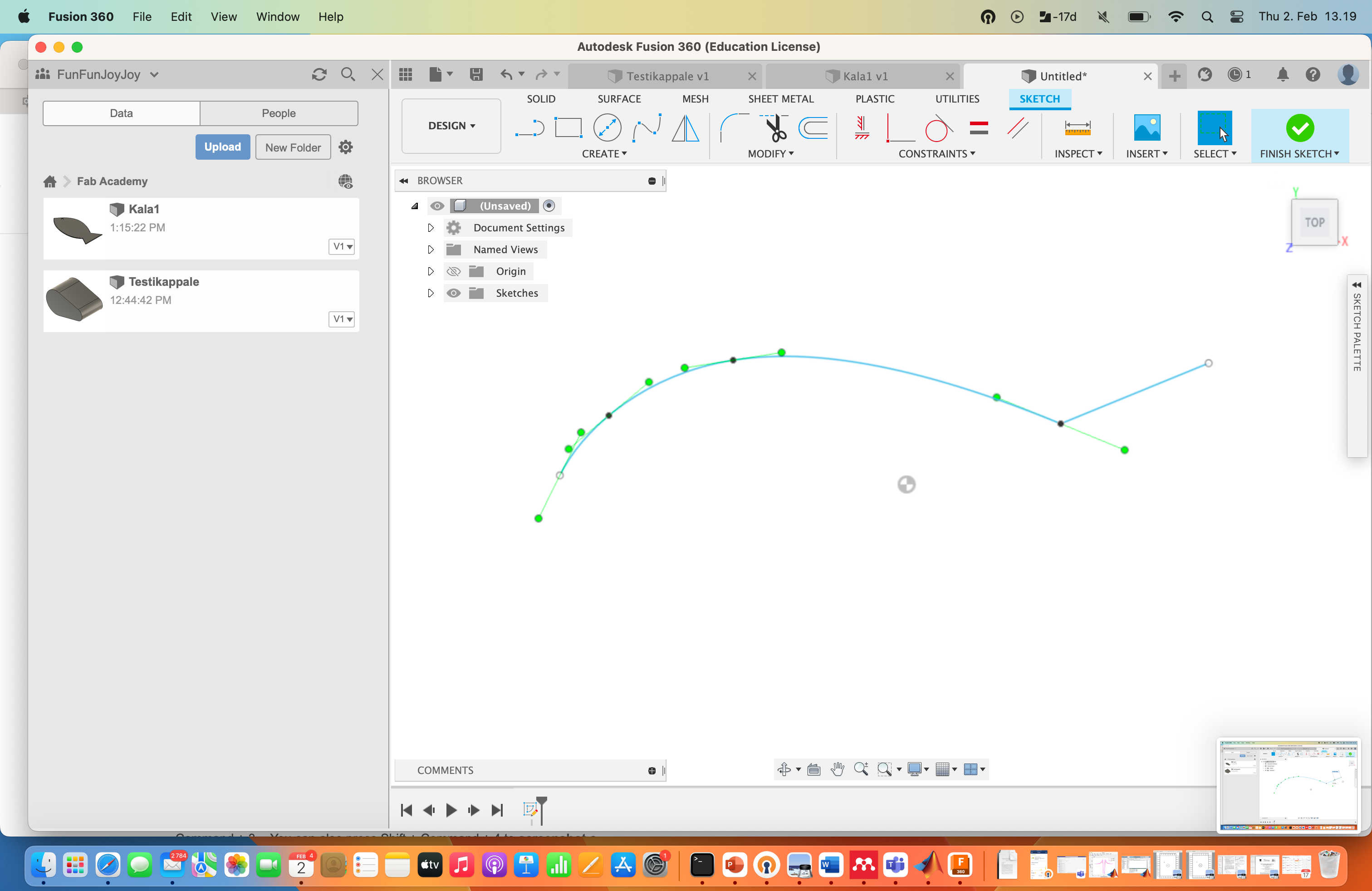
I added a circle for an eye to the design.
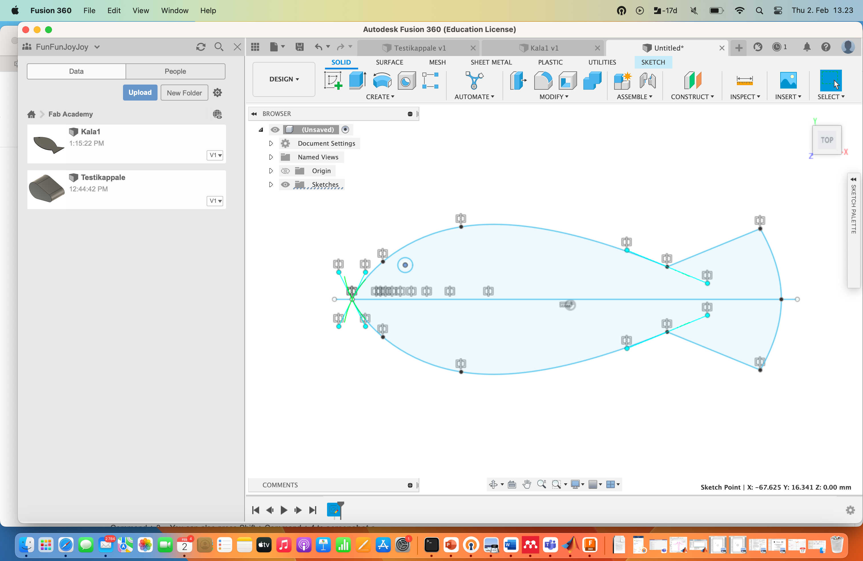
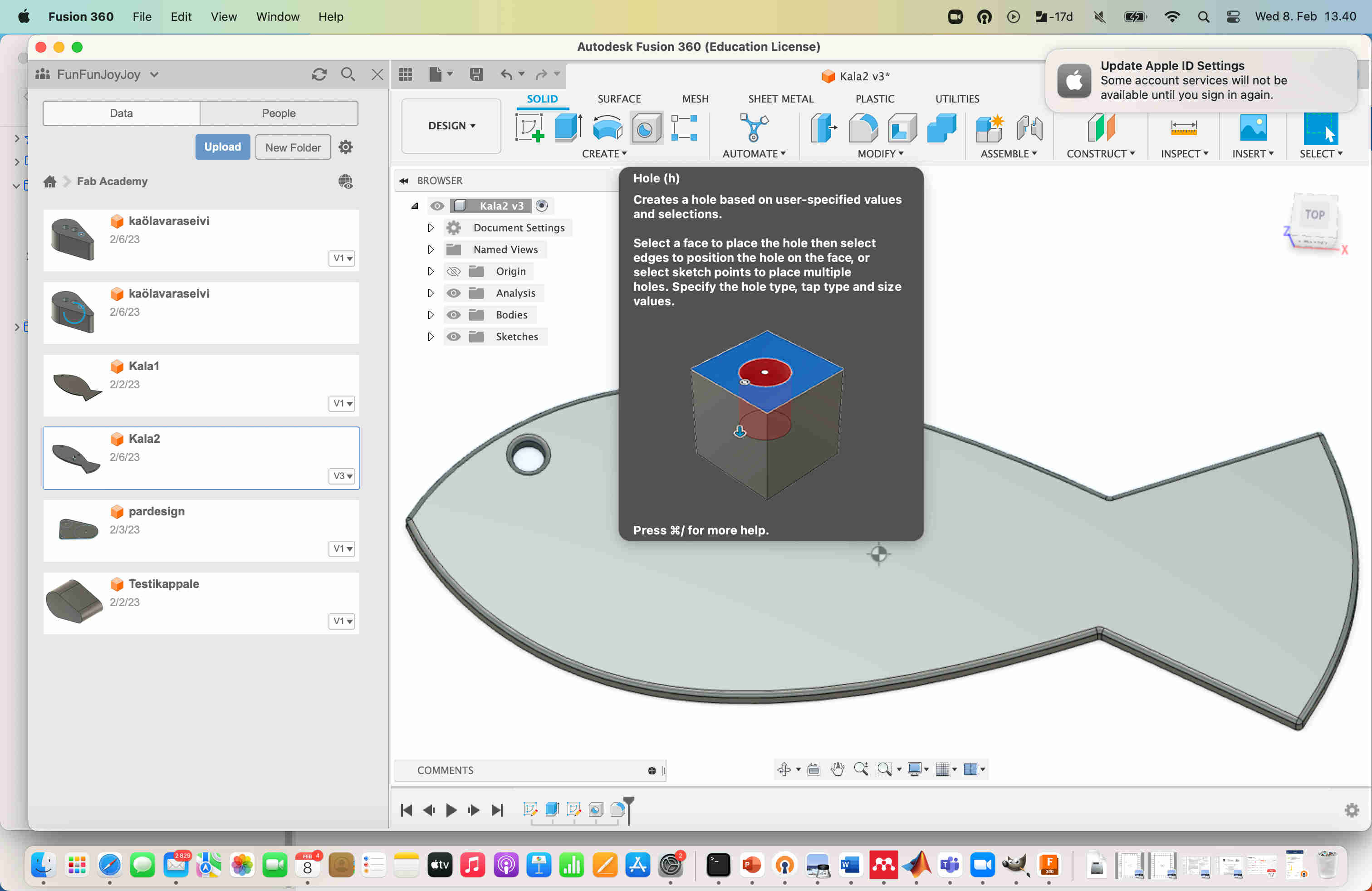
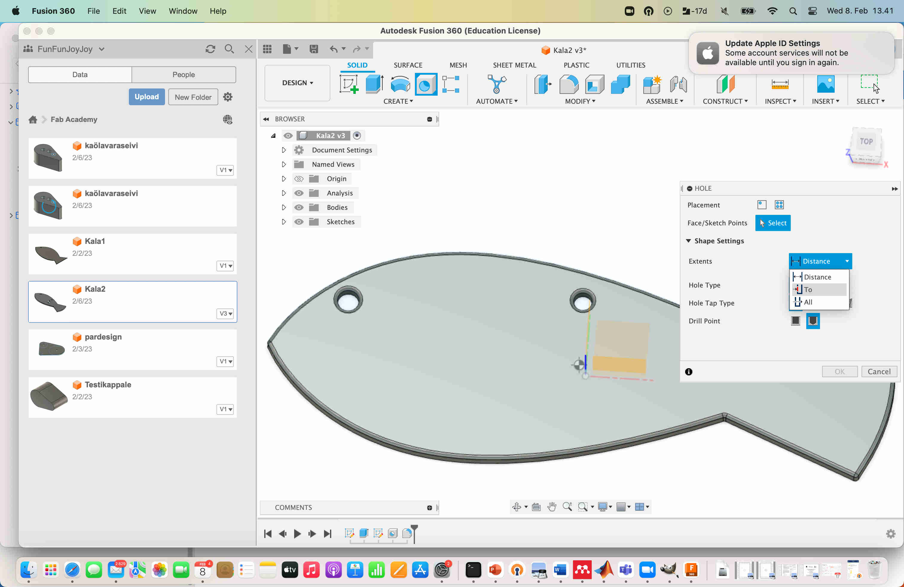
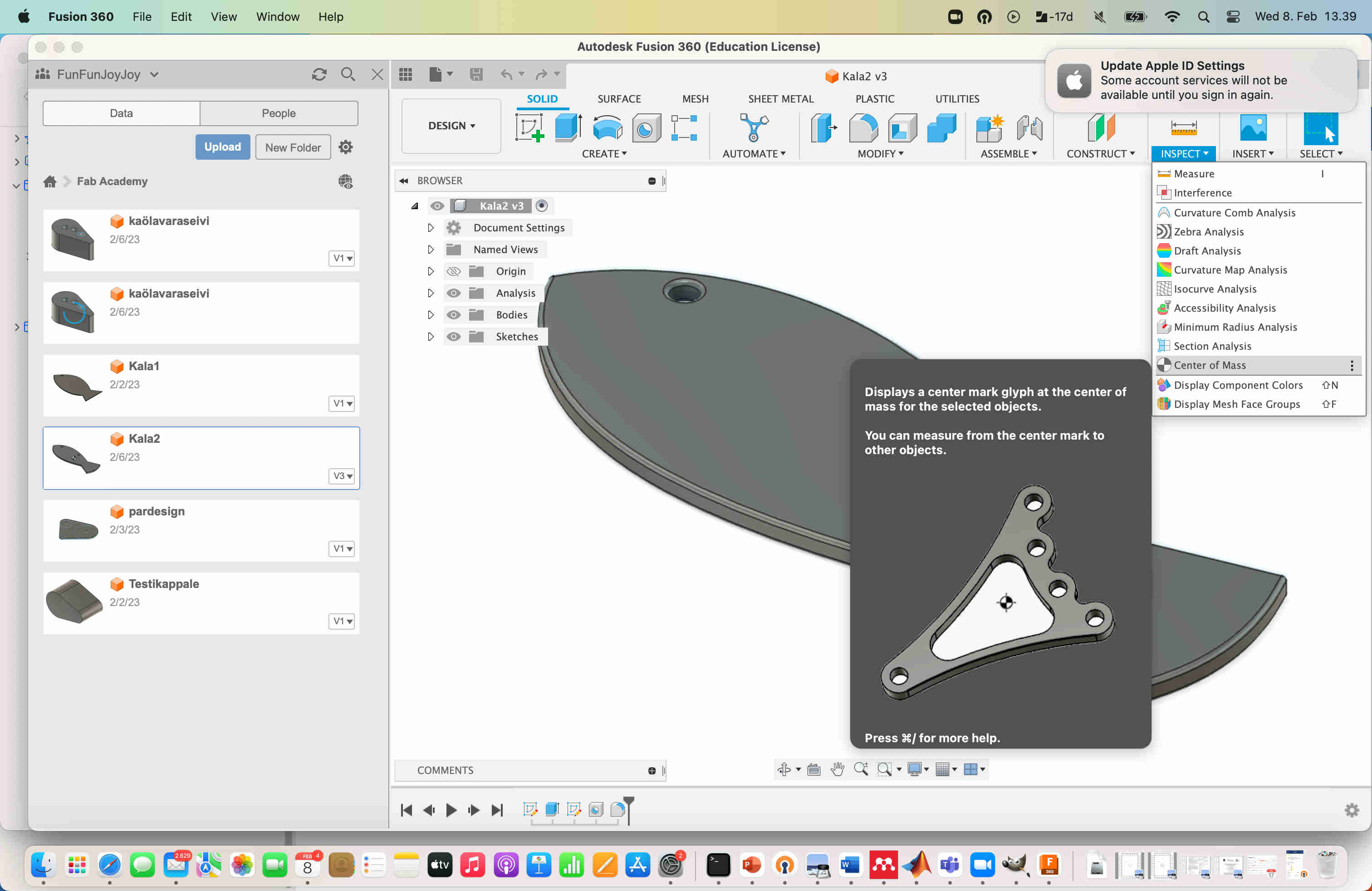
I extruded the fish shape to obtain 3D structure. I measured the center of the mass usign a tool in the Fusion software, and added a hole above the center of mass, so I could hang the fish with a string that would be attached to this hole. I used the hole tool to add the hole.
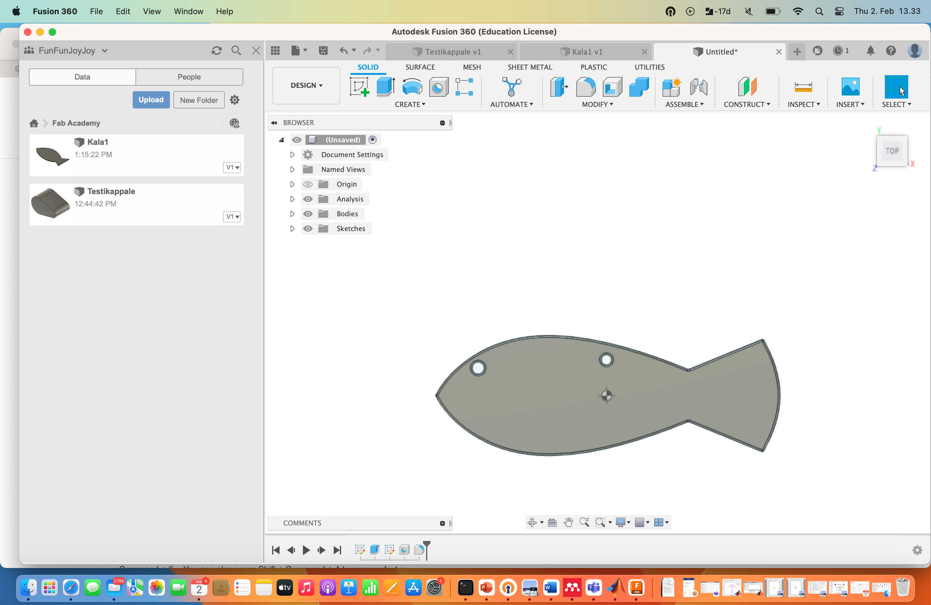
I also added some rounding to the edges of the final 3d design.
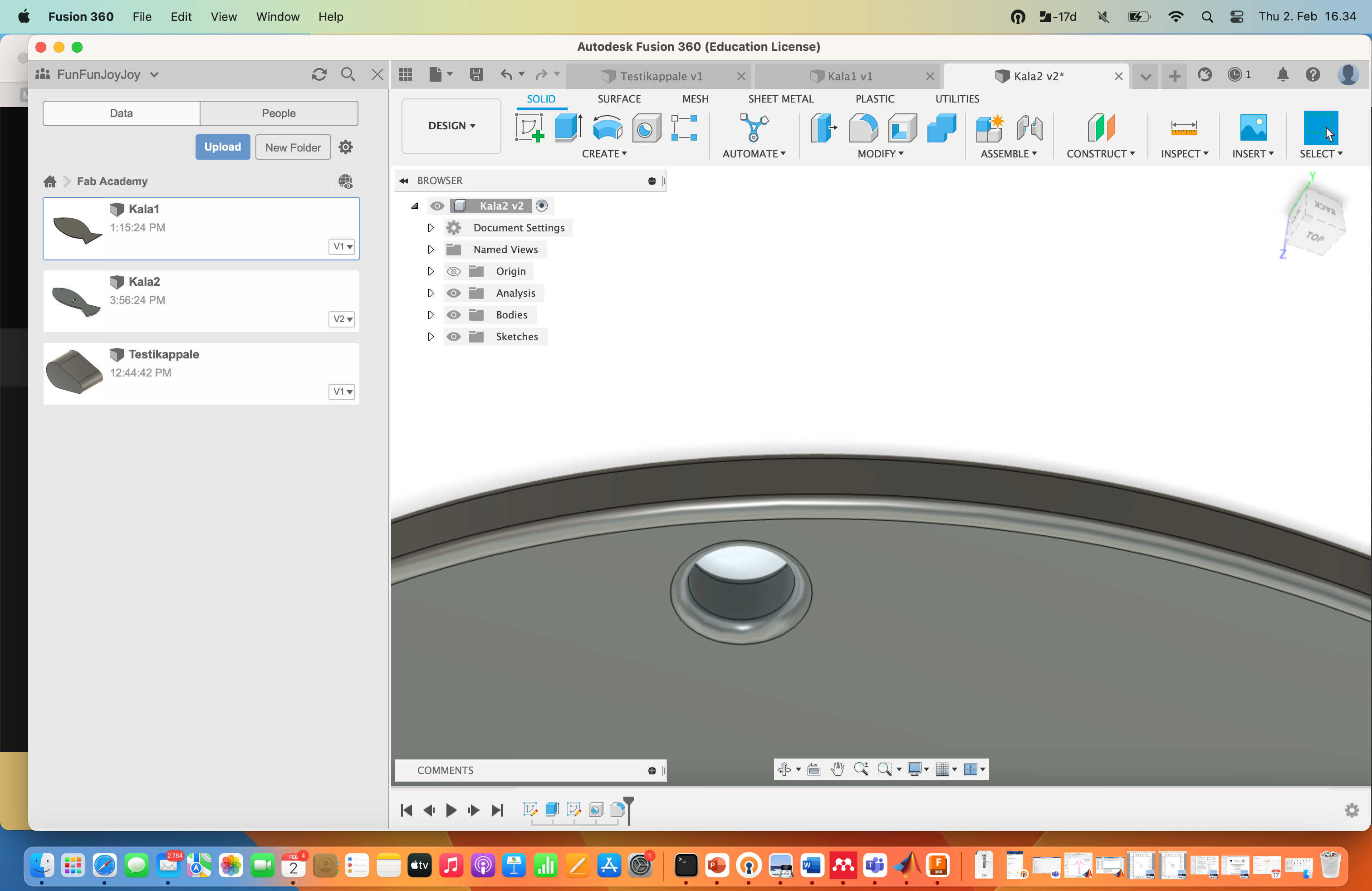
The 3d design file, made with Autodesk Fusion.
Basic editing of raster images with Gimp software
To test basic editing with Gimp software, I took a photo of a suitable object.
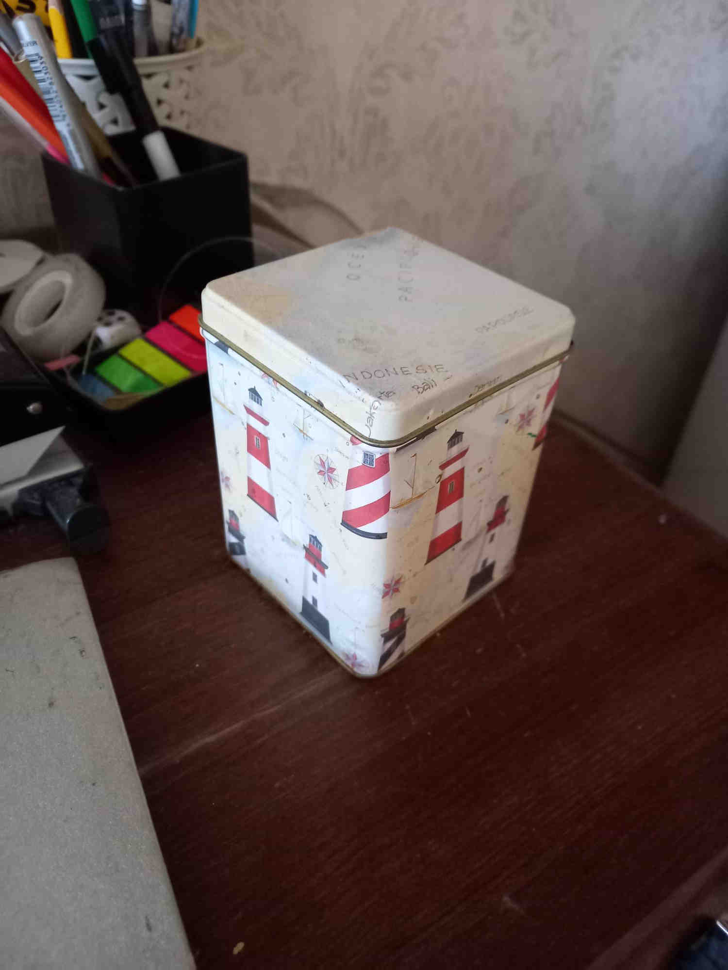
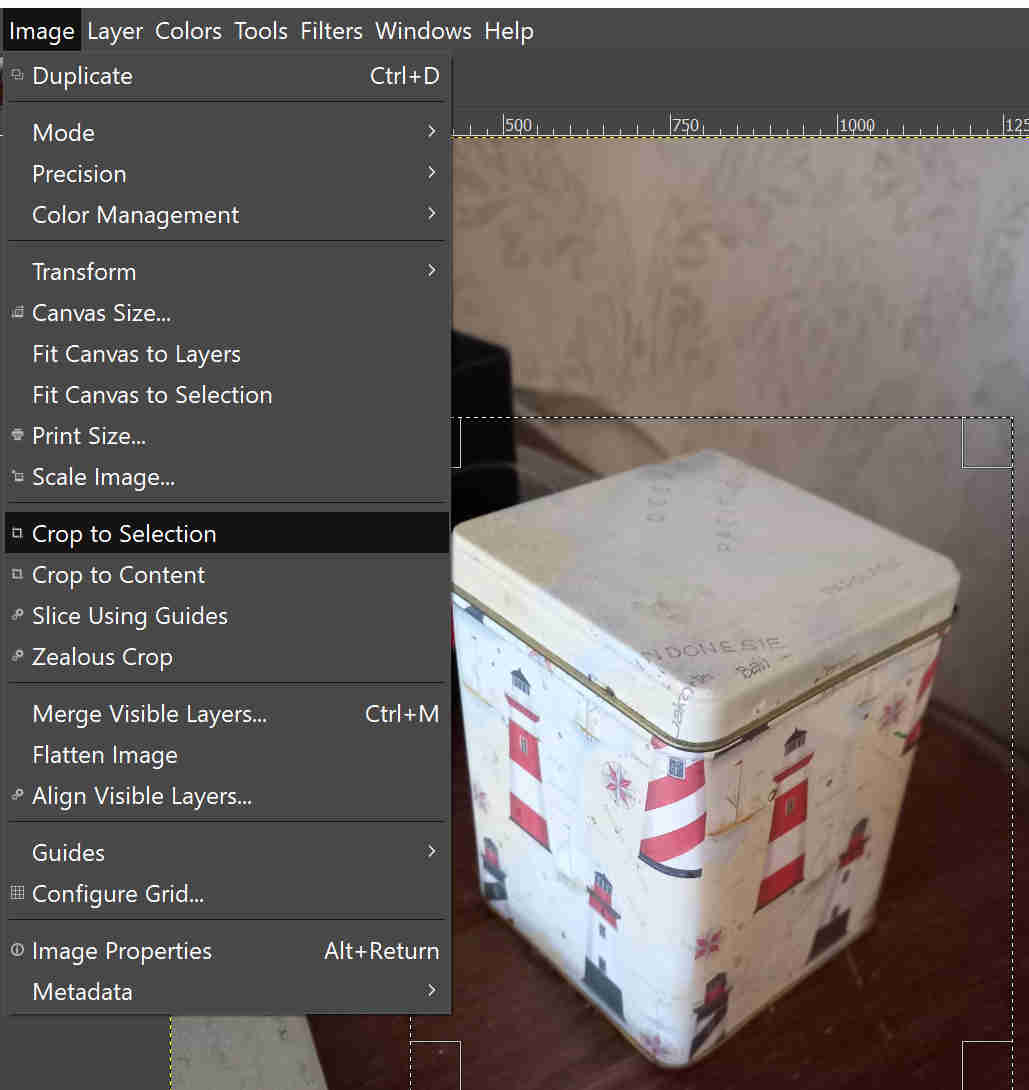
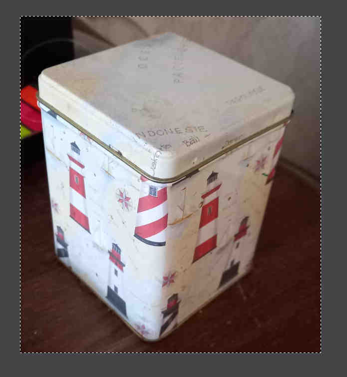
Cropping
To crop an image, I first select the region with the select tool. Then I choose: Image -> Crop to Selection.
Drawing ellipse on an image
To draw an ellipse on an image, I choose: Tools -> Selection Tools -> Ellipse Select.
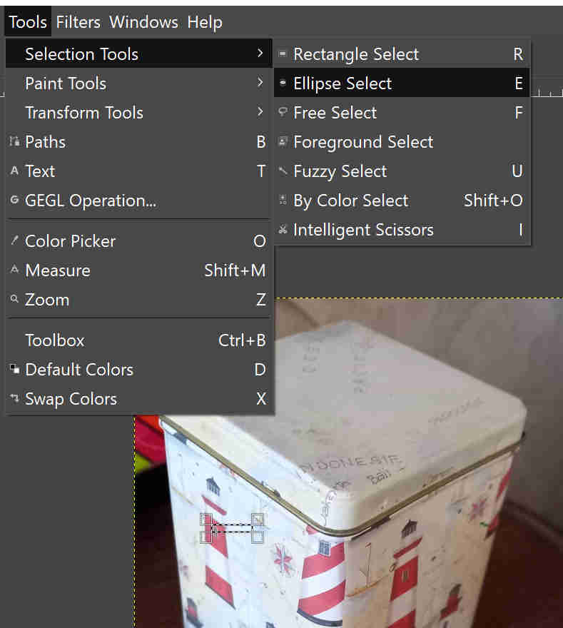
Then using the ellipse selection tool, I draw the ellipse at desired location on the image, and choose Edit -> Stroke Selection.
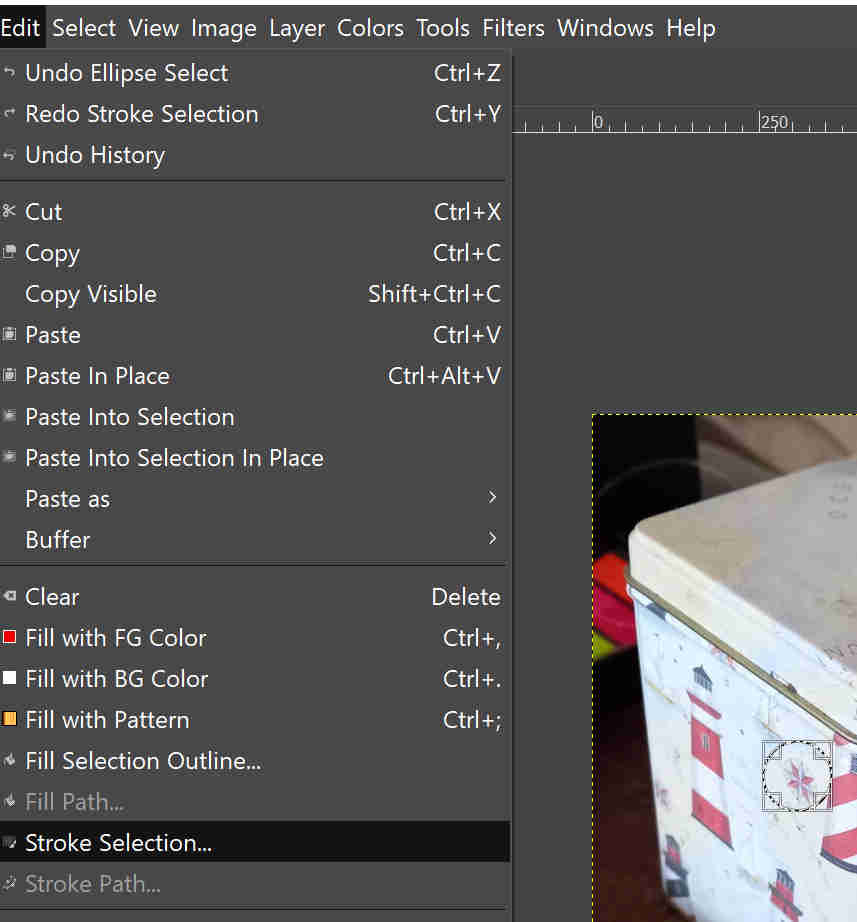
There appears a menu to control line properties, click -> Stroke
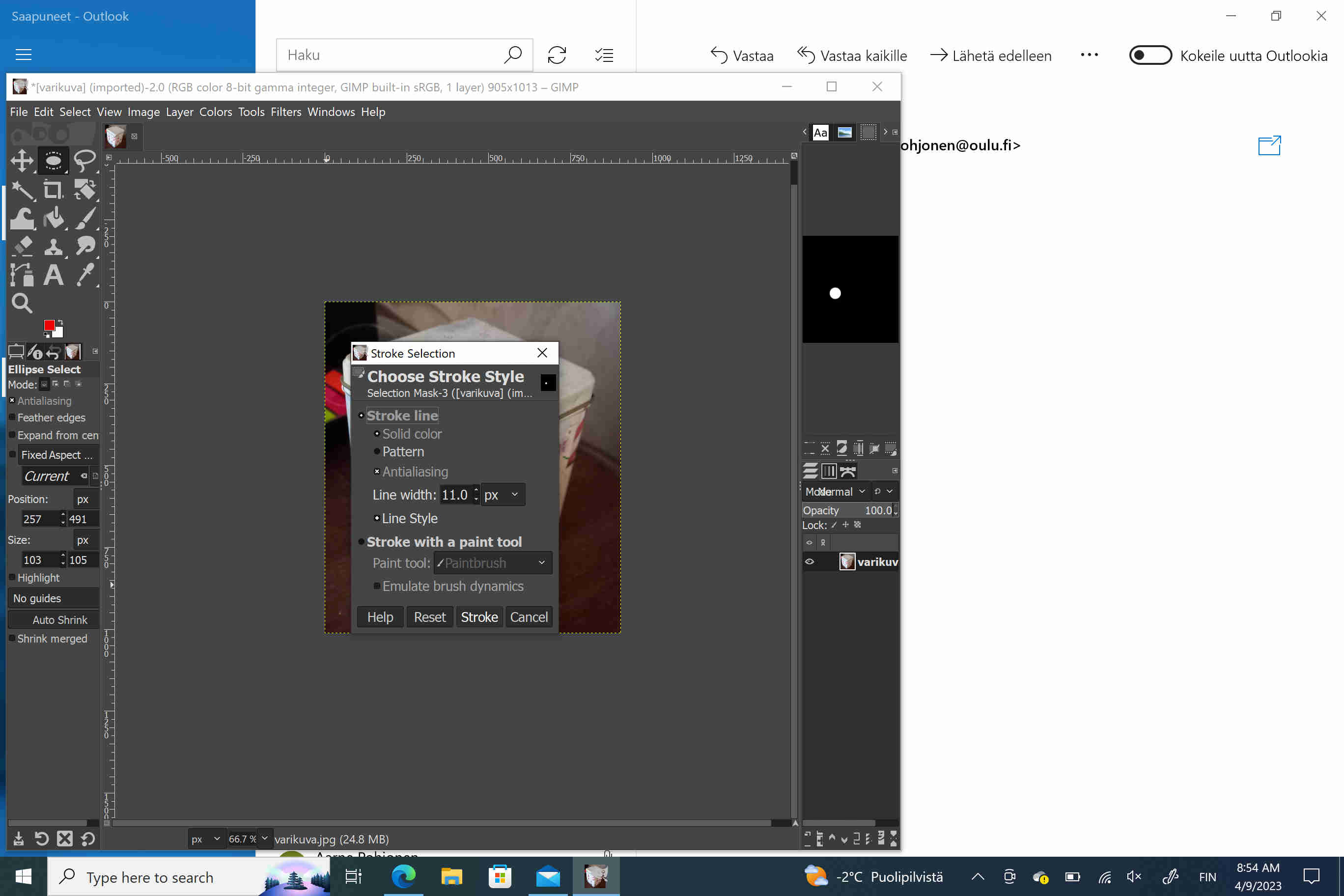
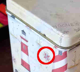
An ellipse is created to the image.
Transforming color image to grayscale
To transform a color image to grayscale image I choose: Colors -> Components -> Decompose.
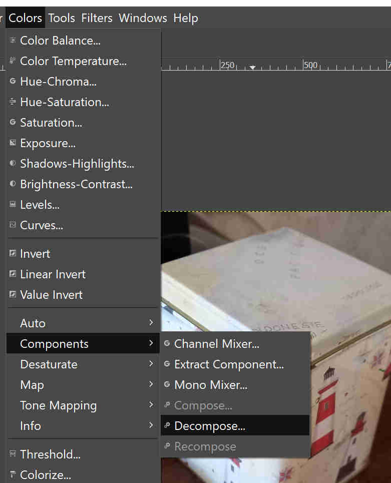
Then I accept the suggested color model RGB, and click -> OK.
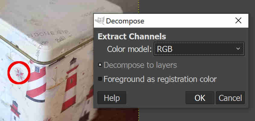
This yields the RGB colors as grayscale image layers.
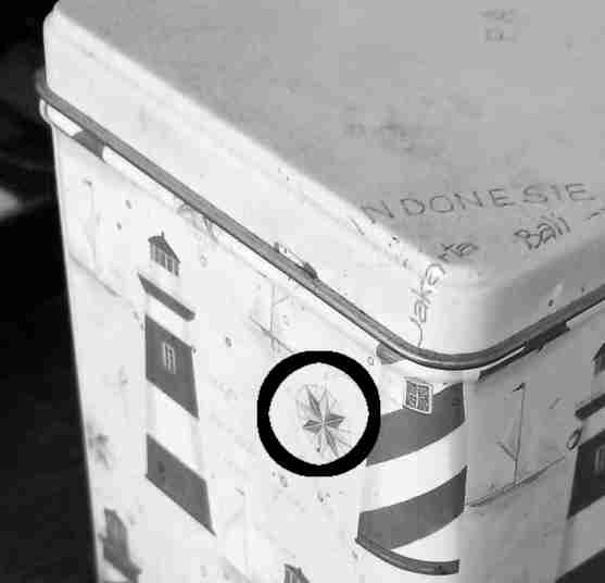
The final image is here.
Designing a 2D line (vector) and raster object using Inkscape
Basic inkscape usage: drawing Bezier curves for laser cutting
In inkscape, it is convenient to draw smooth paths for laser cutting. This is achieved by using Bezier curves. They can be created easily using menu selection:
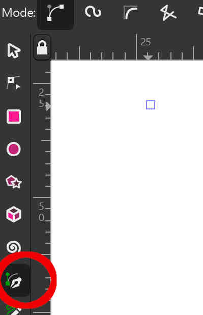
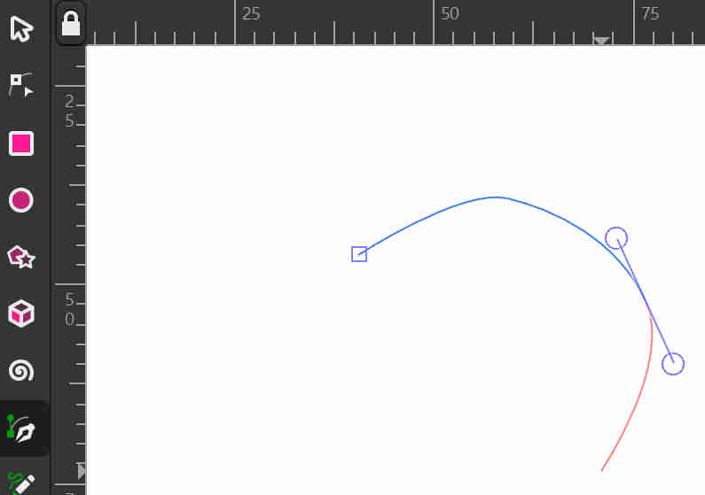
After selecting the Bezier curve tool, the path can be created on the drawing screen. Holding the left mouse button down allows to chnange orientation of the line, and this way the line can be made smooth.
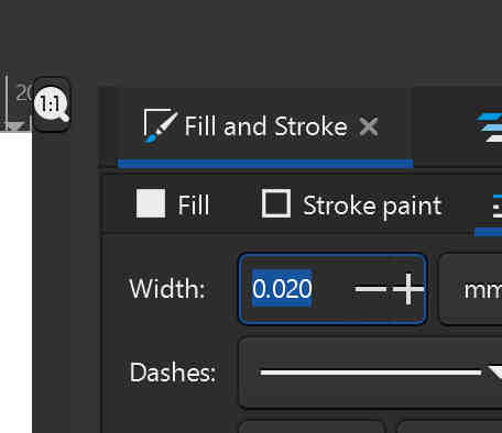
For laser cutting, it is necessary to modify the line thickness. The lines that are sufficiently thin will be cutted with laser, and thicker lines will be engraved. To change the line thickness, I select the line, and then object -> fill and stroke. In the side panel, which opens, the width can be changed.
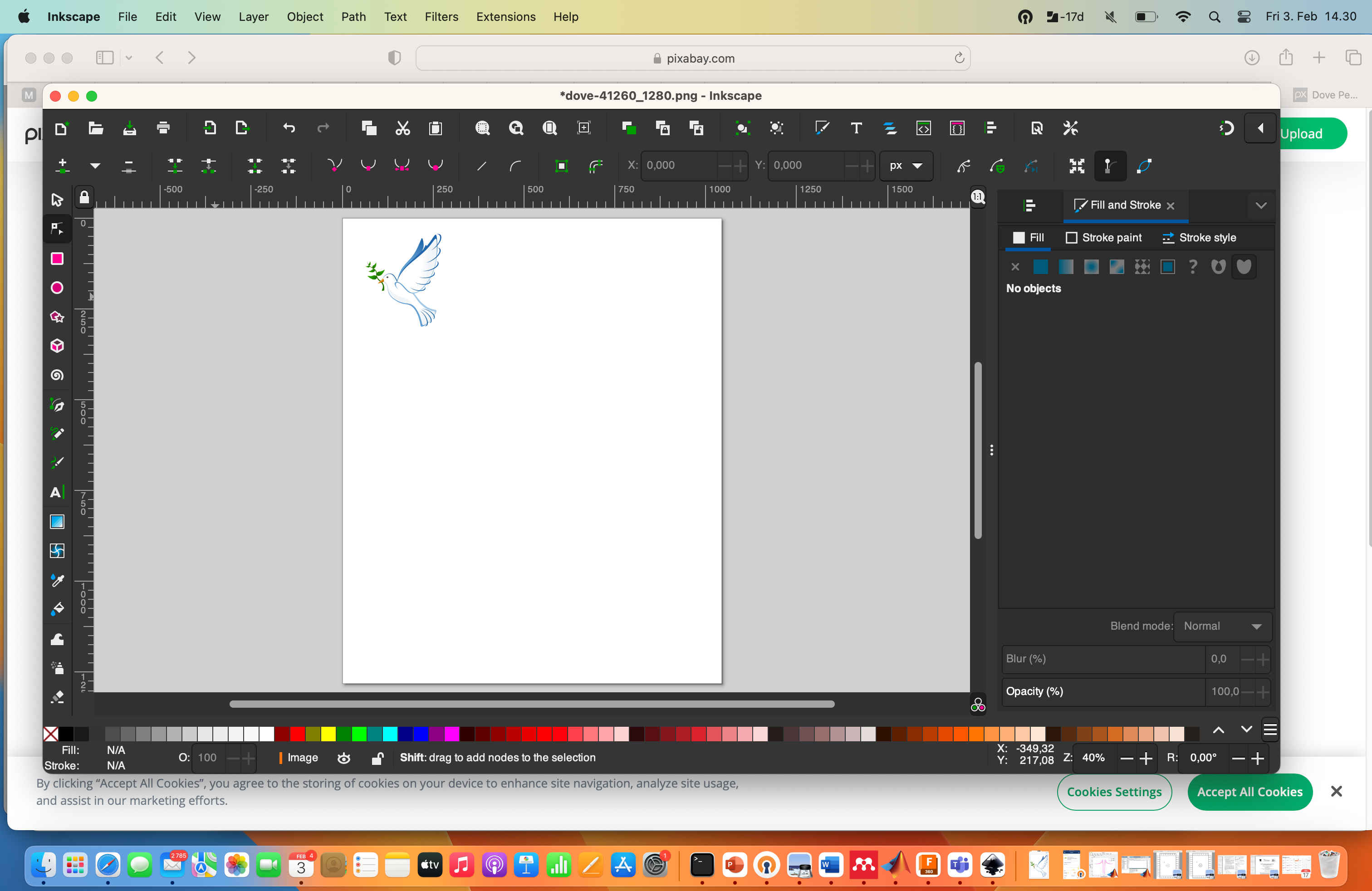
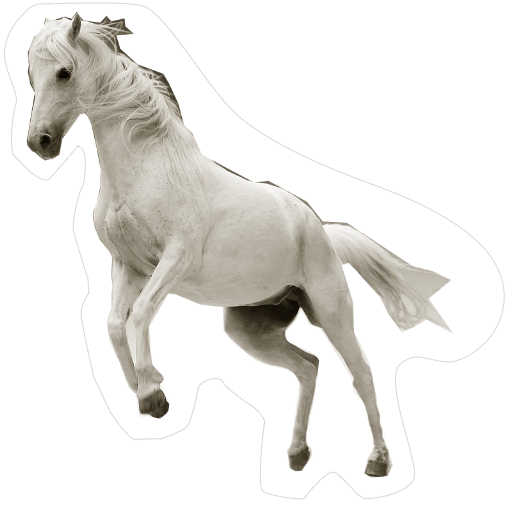
From Pixabay, I downloaded an image of bird symbolizing peace, (image by Clker-Free-Vector-Images from Pixabay)
I opened the file using Inkscape, and drew a spline around the bird, set the line thickness to 0.02 mm, and saved the file to a pdf file.
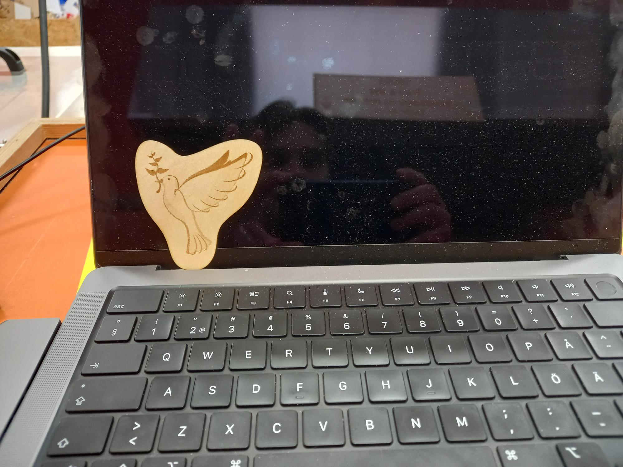
Then I printed the file, which sent it to the laser cutter. I choose 3 mm plywood material with cut and engrave.
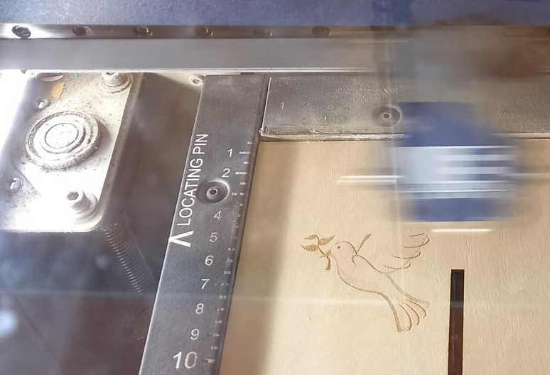
The final result turned out fine and peaceful.
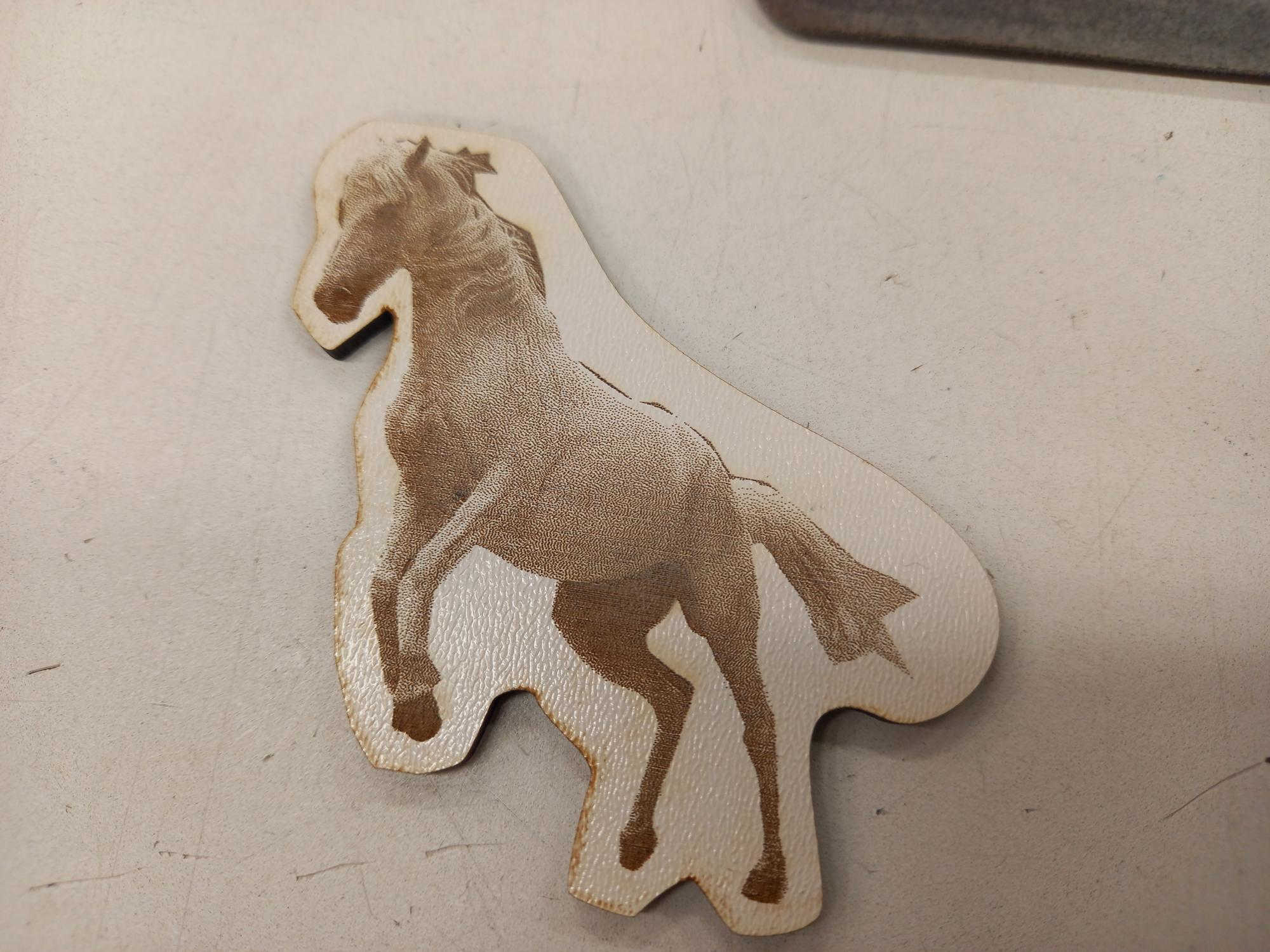
I tested some additional vector and raster cutting jobs. For a second test, I made a raster image of a horse created by Sponchia, which I downloaded from pixabay, where I created a surrounding line for cutting.
The raster was engraved nicely on the painted material. In the lower side, there appeared some brown color near to the cut line.
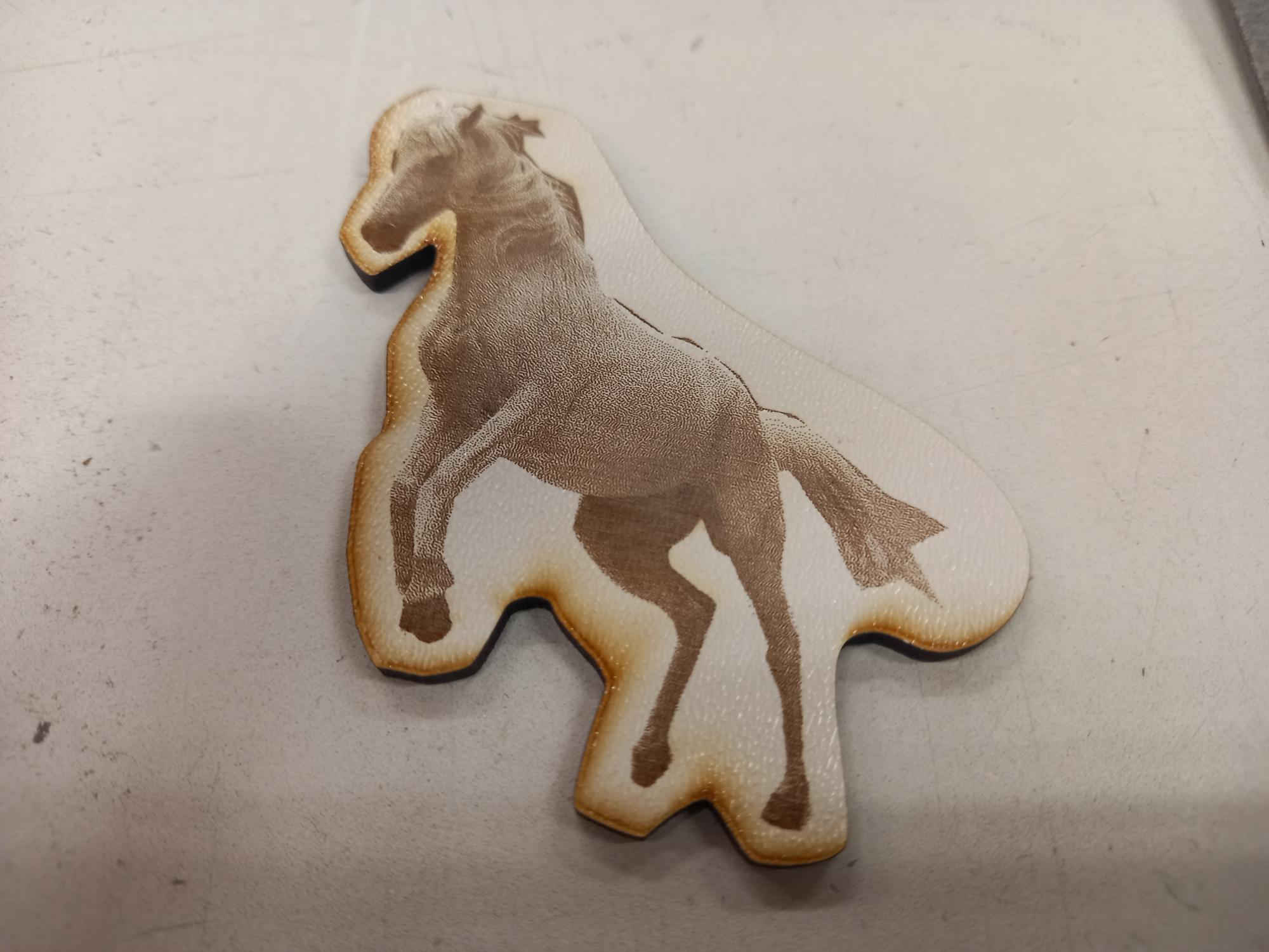
I asked the lab instructor for the reason for the brown color, and he explained that it is because of the air, which is blown to the material from that direction, and that it can be easily wiped away with a wet paper. I wiped the edges, and got rid of the brown color.
Parametric design with FreeCAD
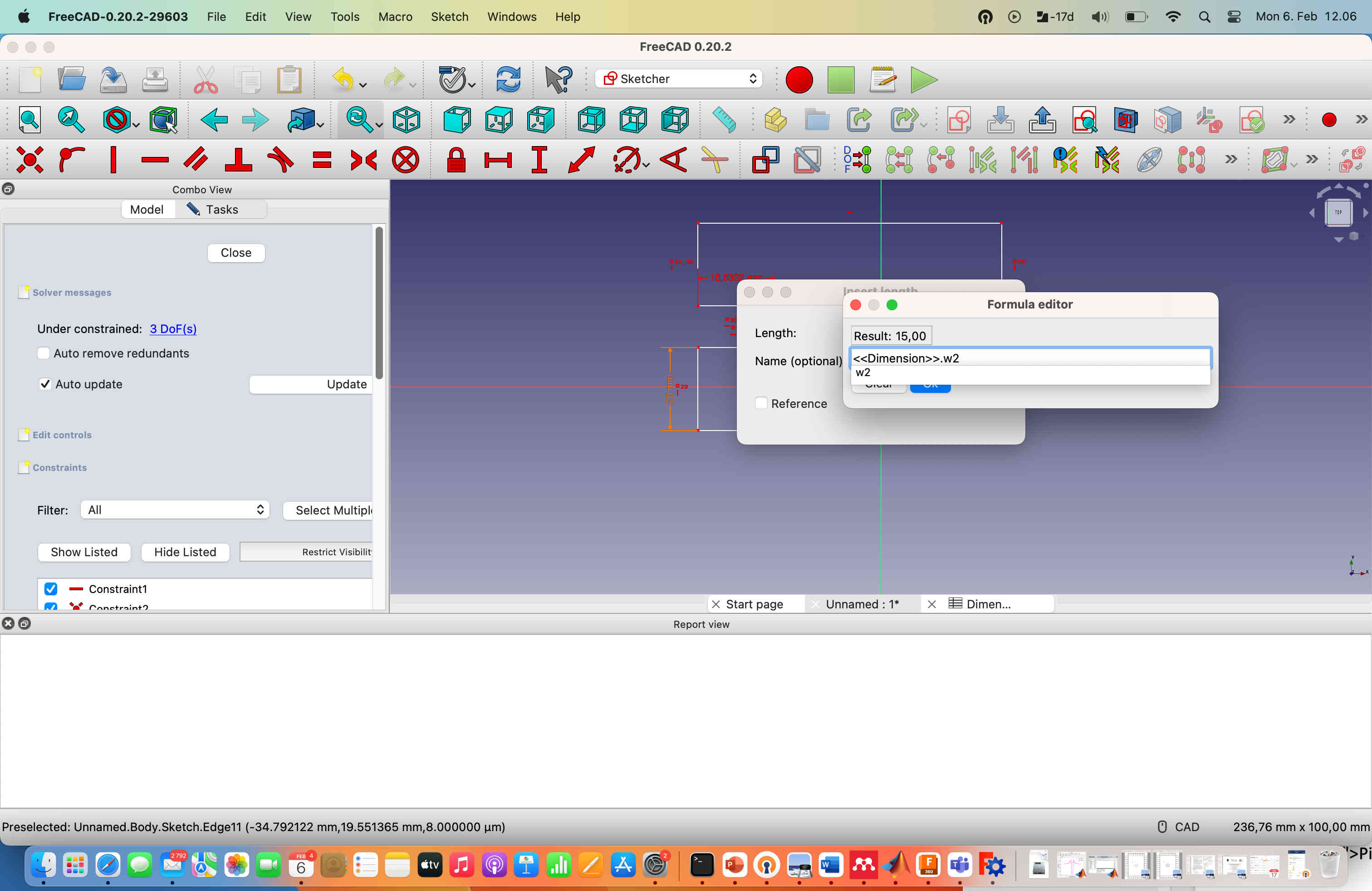
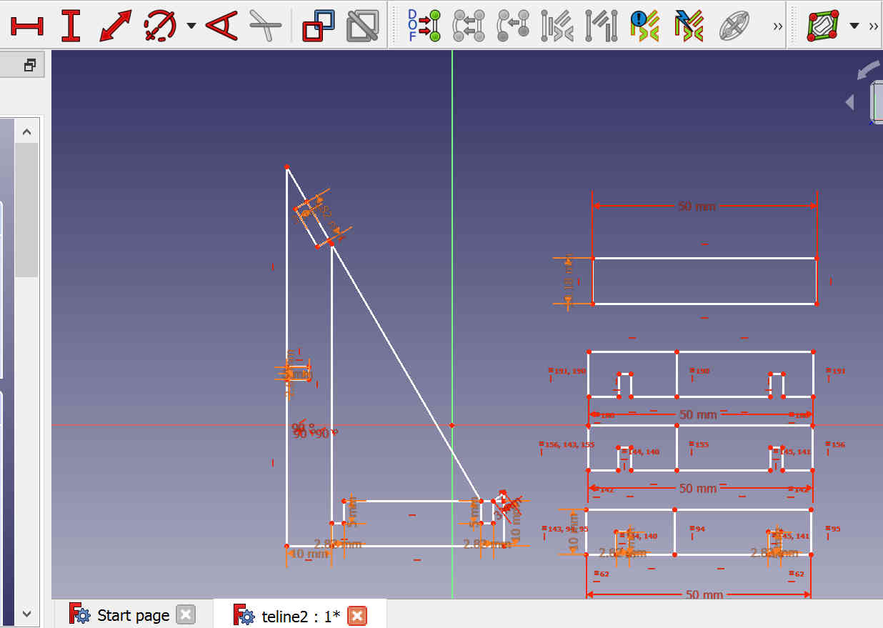
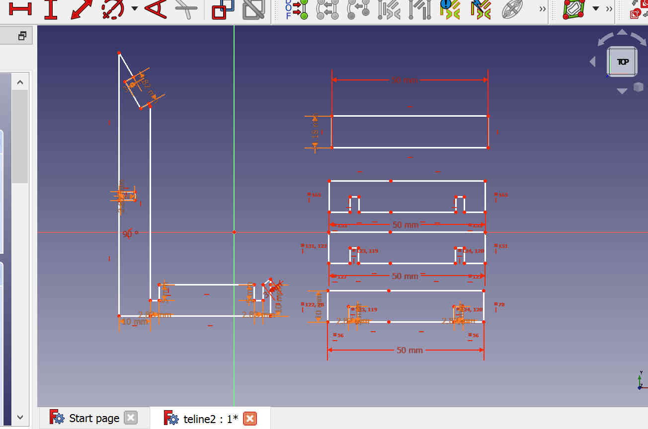
I tested parametric design using FreeCAD software. First, I drew an object using polyline, constrained horizontal and vertical lines, and made a length constraint for few sides.
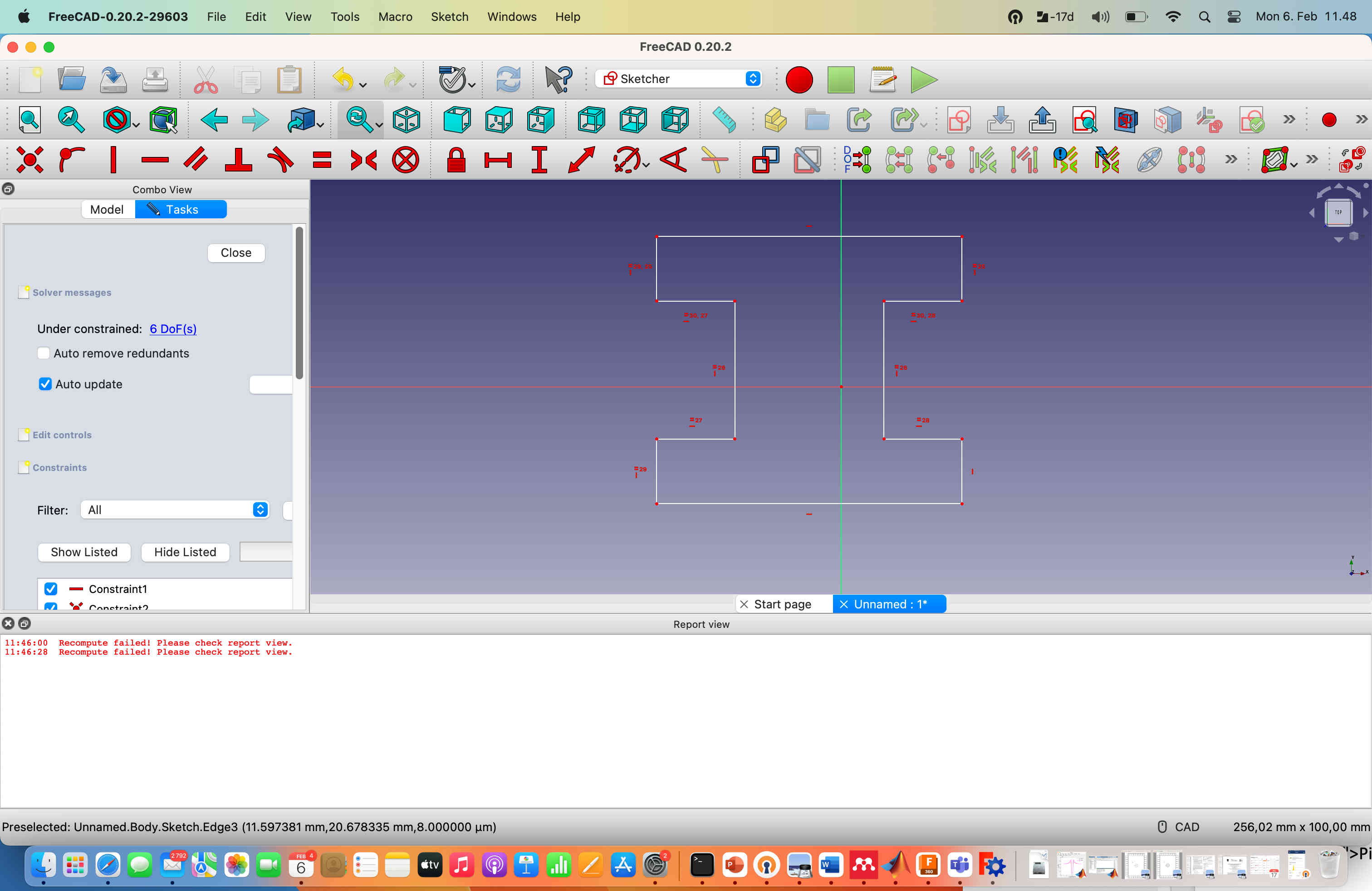
Then I used spreadsheet tool to create parameters for the design, so that I can easily change the geometr using those parameters. I named the parameters h1, h2, w1 and w2. I then used these parameters in the sketch to determine the geometry, which would be applied when I recalculated the object.
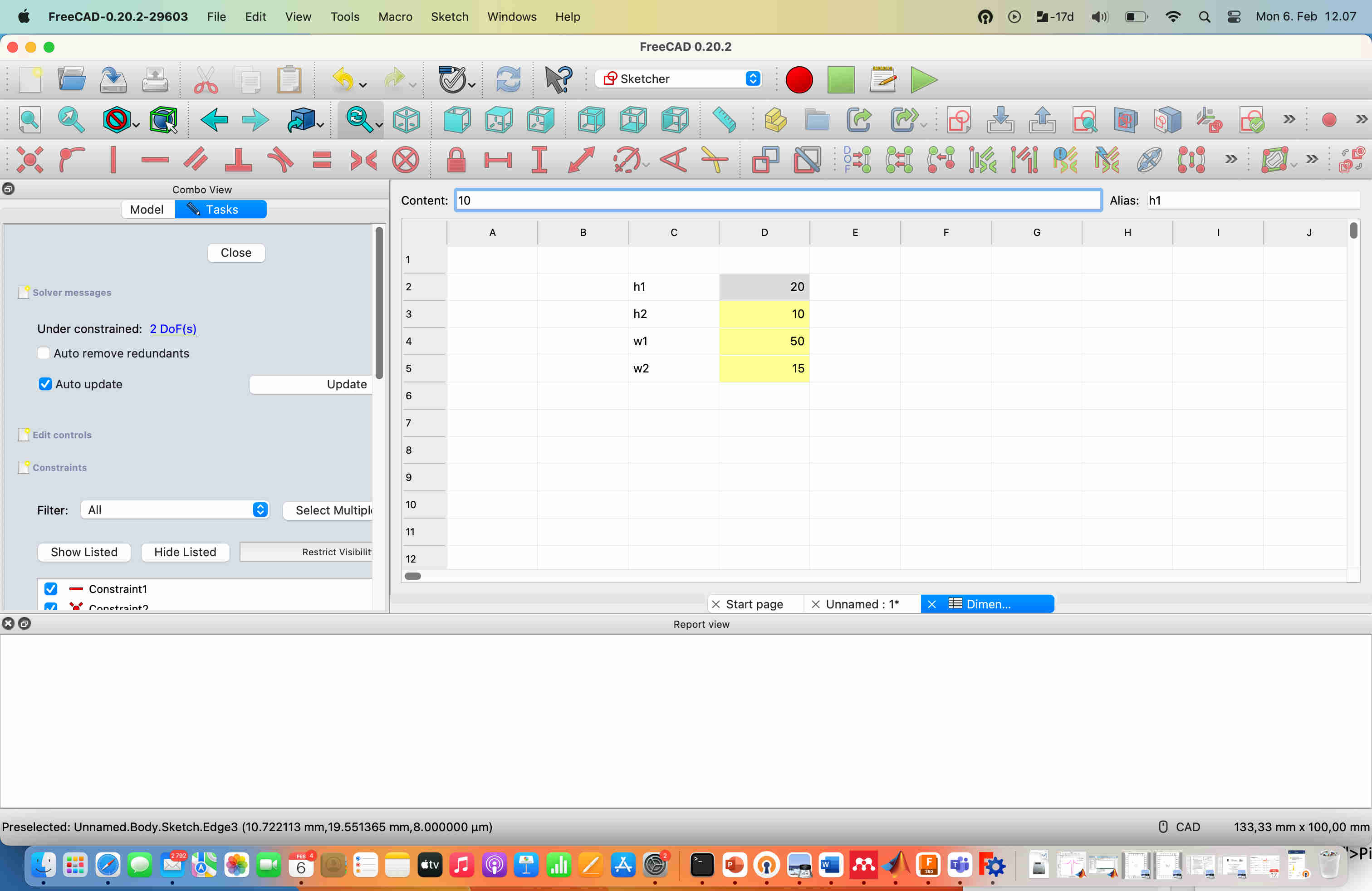
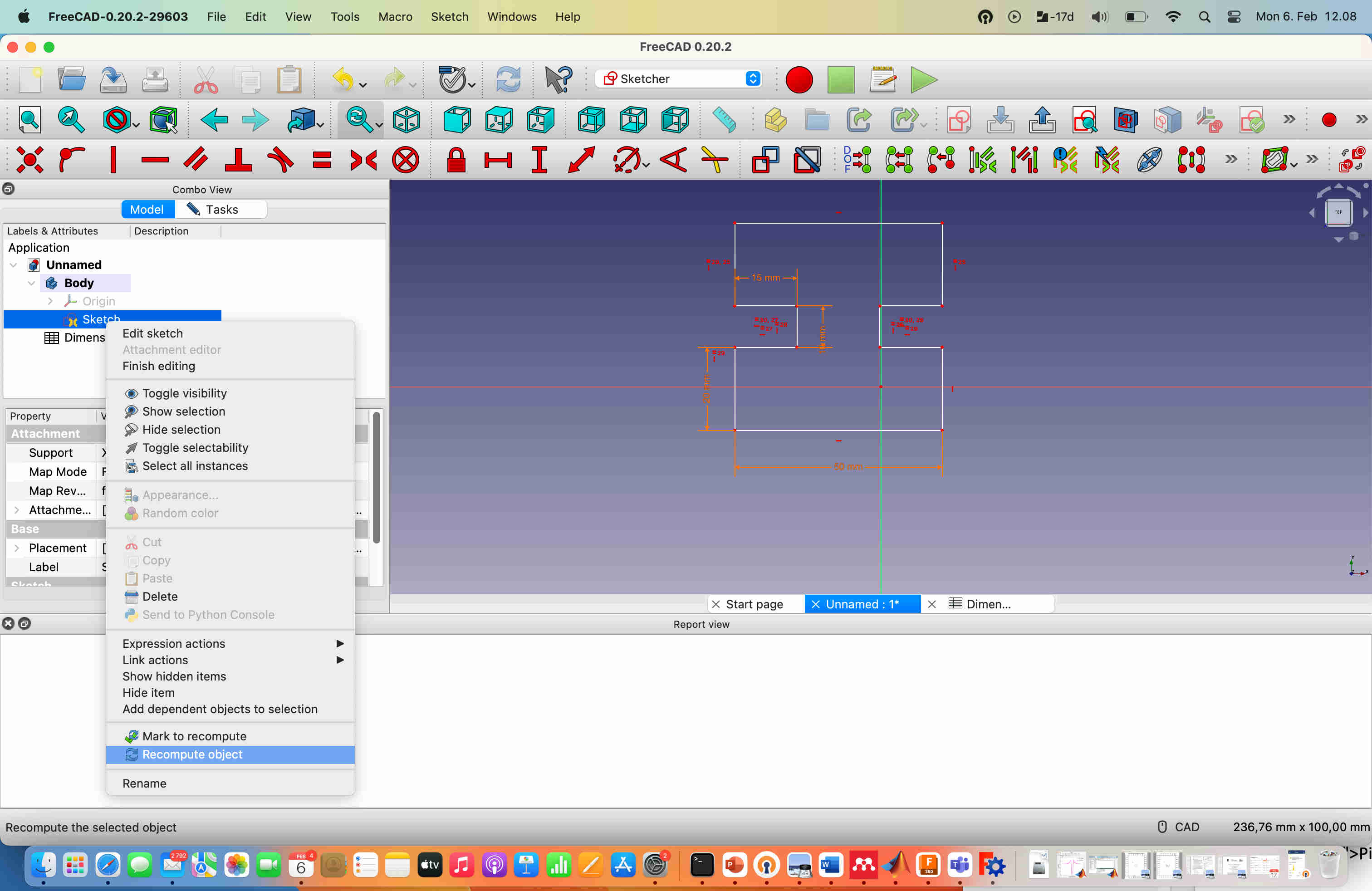
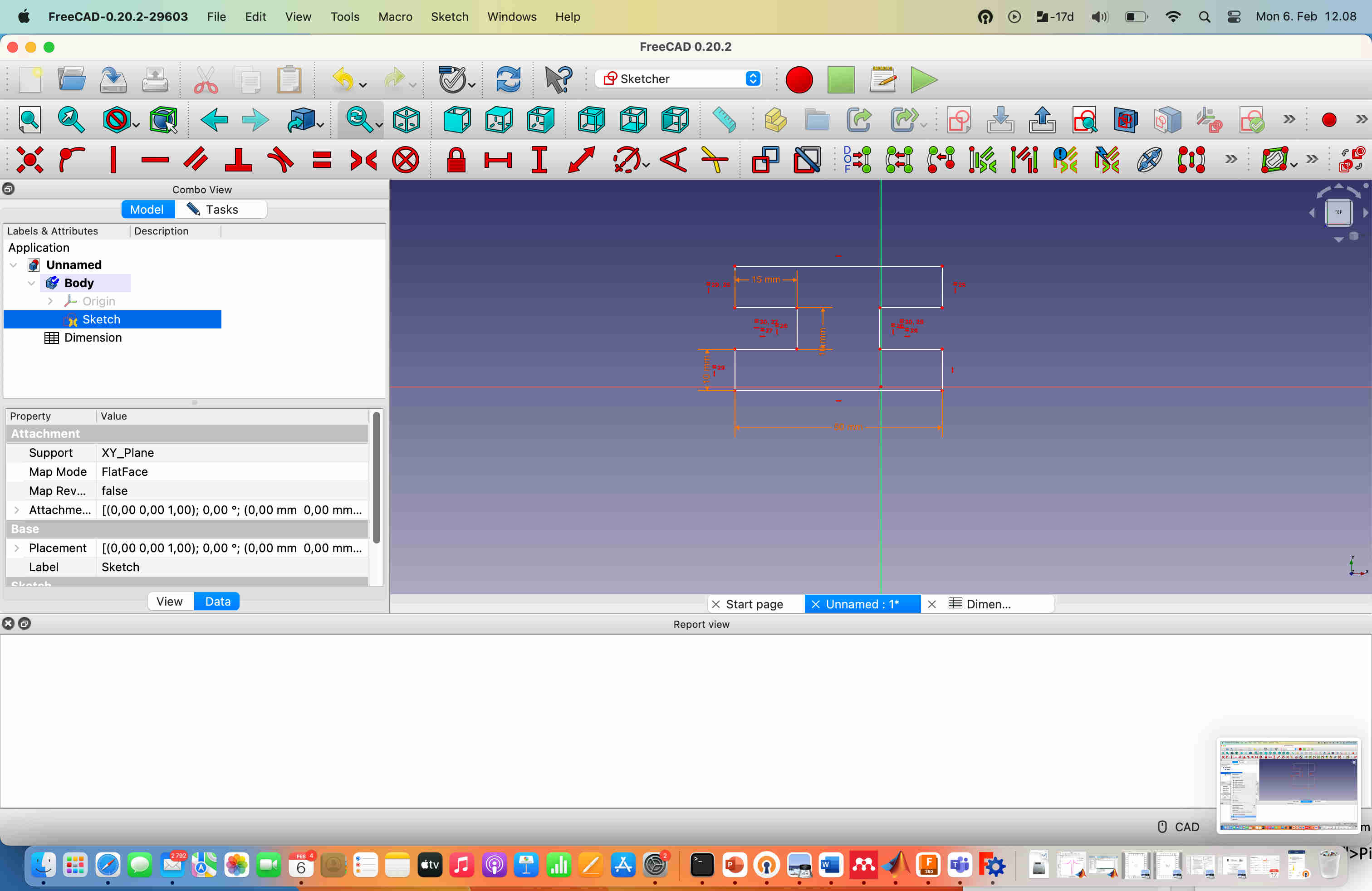
Changing the parameter values in the spreadsheet change the parameters in the sketch.
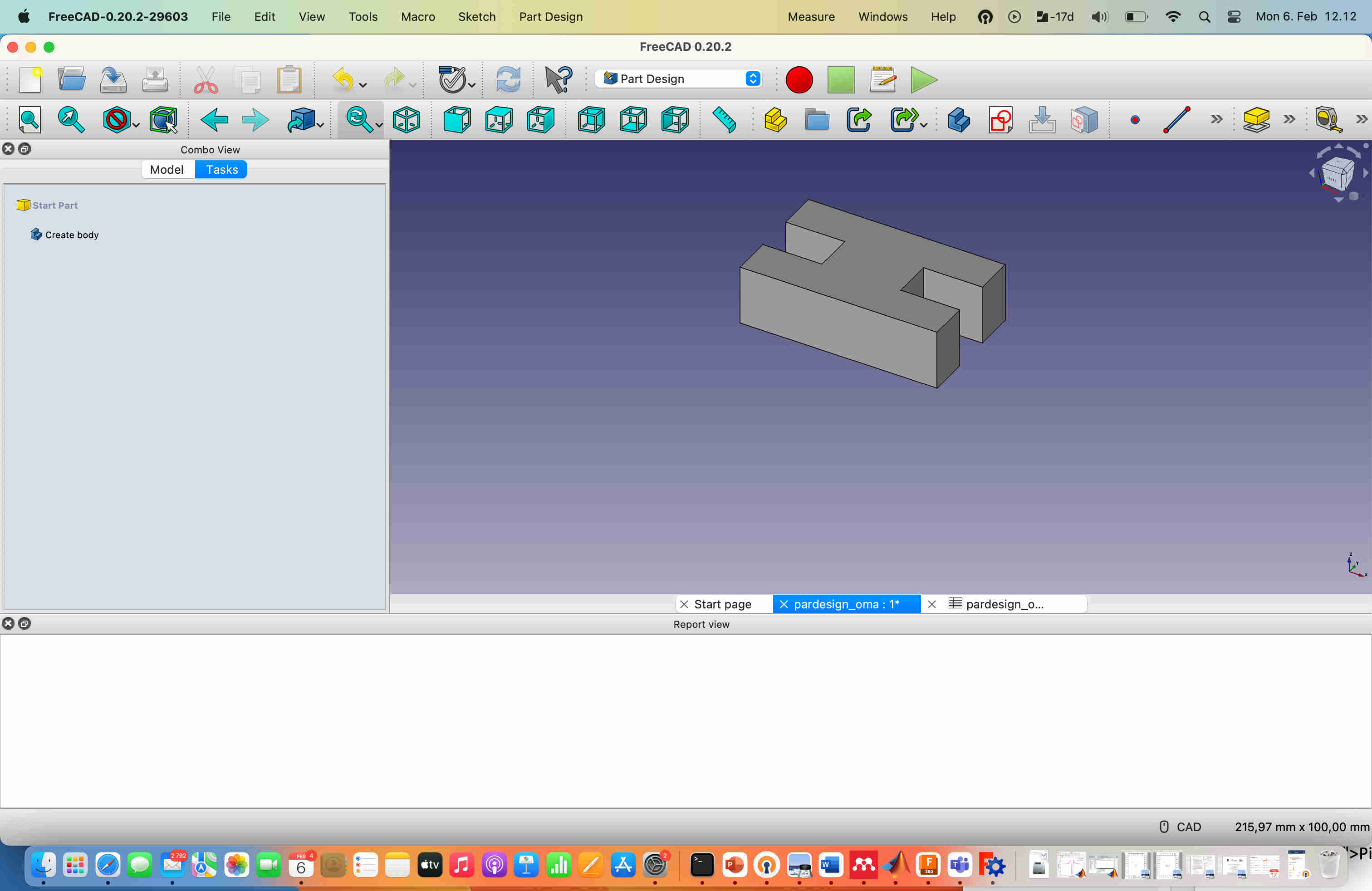
I tested to add 3rd dimension to the object by using pad tool.
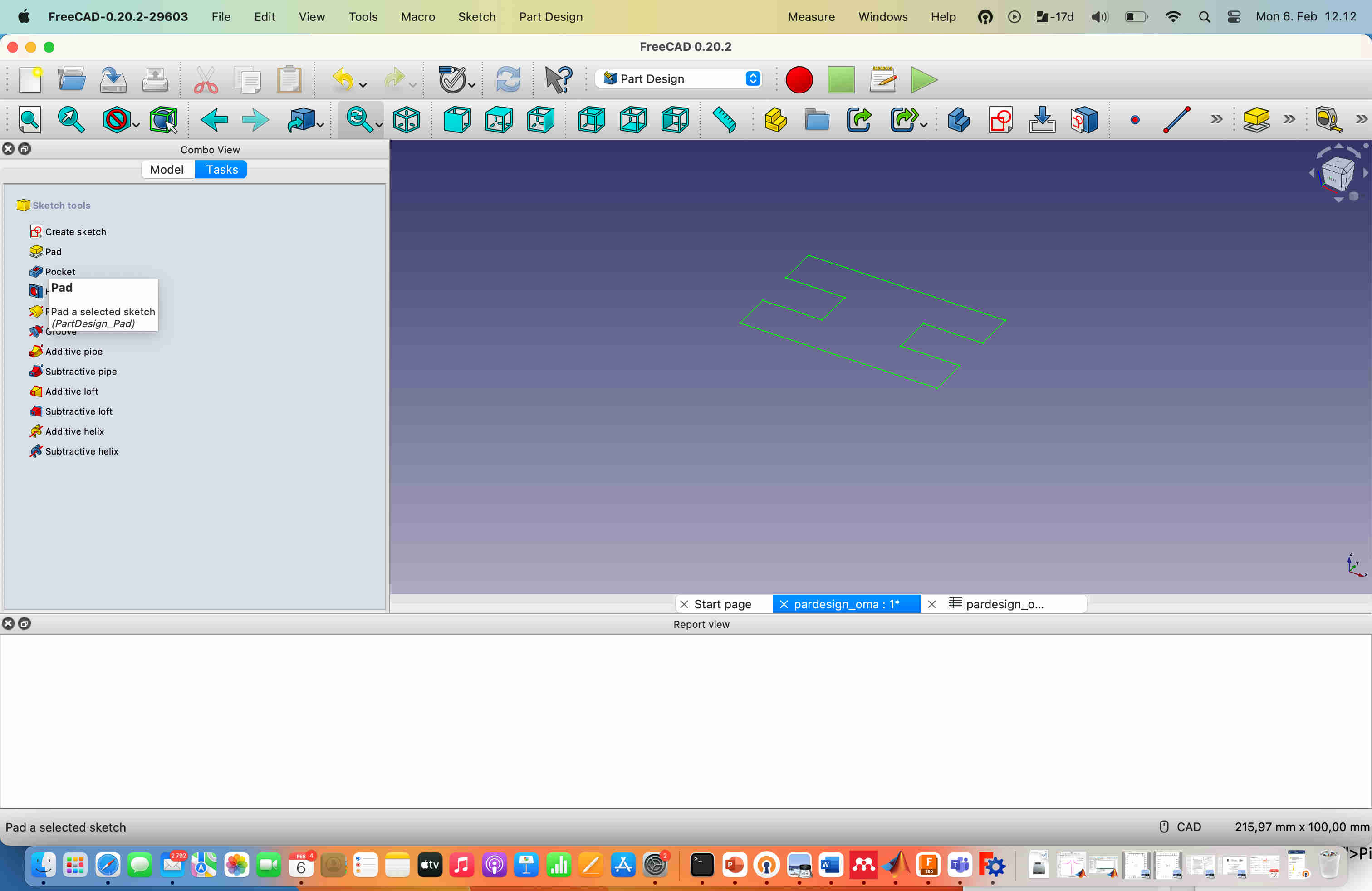
The end result was a 3D object, where the parameters could be used to control the geometry.
The FreeCAD files for the first parametric design:
Designing a post card stand
I wanted to do another design, that would have some application purpose. I decided to make a stand that could be used for postcards. In the same way as in the previous example, I used FreeCAD to design the parts, and took kerf in to account using the spreadsheet tool. I used helper lines to make certain parts to be aligned in the correct way.
When I was ready with the design, I wanted to export the result to svg file and transfer it to inkscape, so I could prepare it for laser cutting. At this stage I removed the helper lines from the design.
Then I exported the design to svg (I selected the parts in Sketch mode, choose File -> export -> Flattened svg).

The FreeCAD files for the postcard stand:
Then I opened the svg file with inkscape, set the line thickness to 0.02 mm and exported to pdf, and proceeded to cut the parts in the same way as explained above. The cut parts fit together well, as shown in the documentation of Computer Controlled Cutting week.
Rigid body simulation with Blender
I wanted to try to use Blender to make a simple rigid body simulation. I found a good tutorial written by Ryan Bury, that explained the basic steps but here I used torus instead of a ball.
The most important commands for navigating and adding/removing items are:
I started blender and deleted the initial cube. Then I added a plane to the geometry
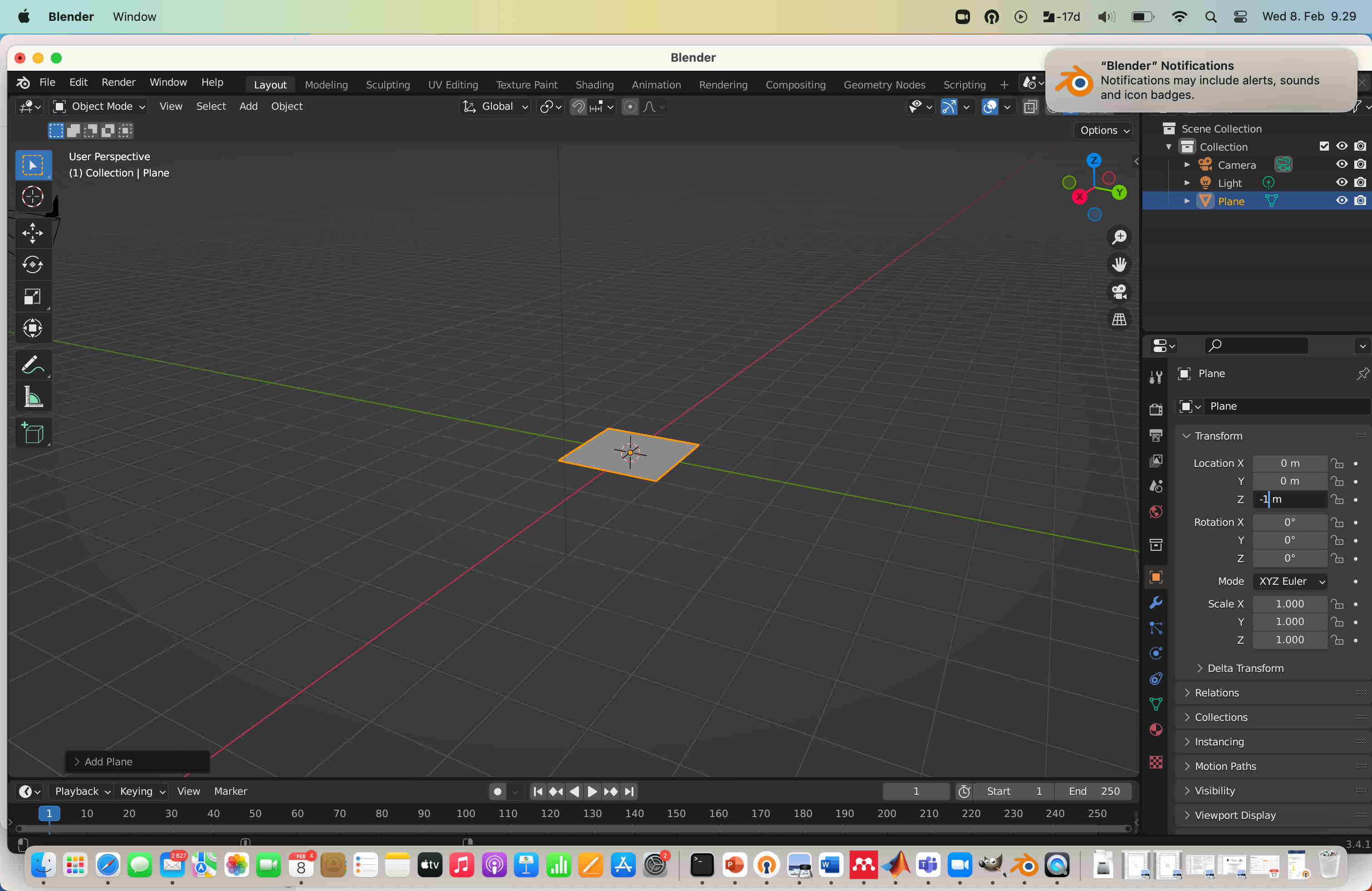
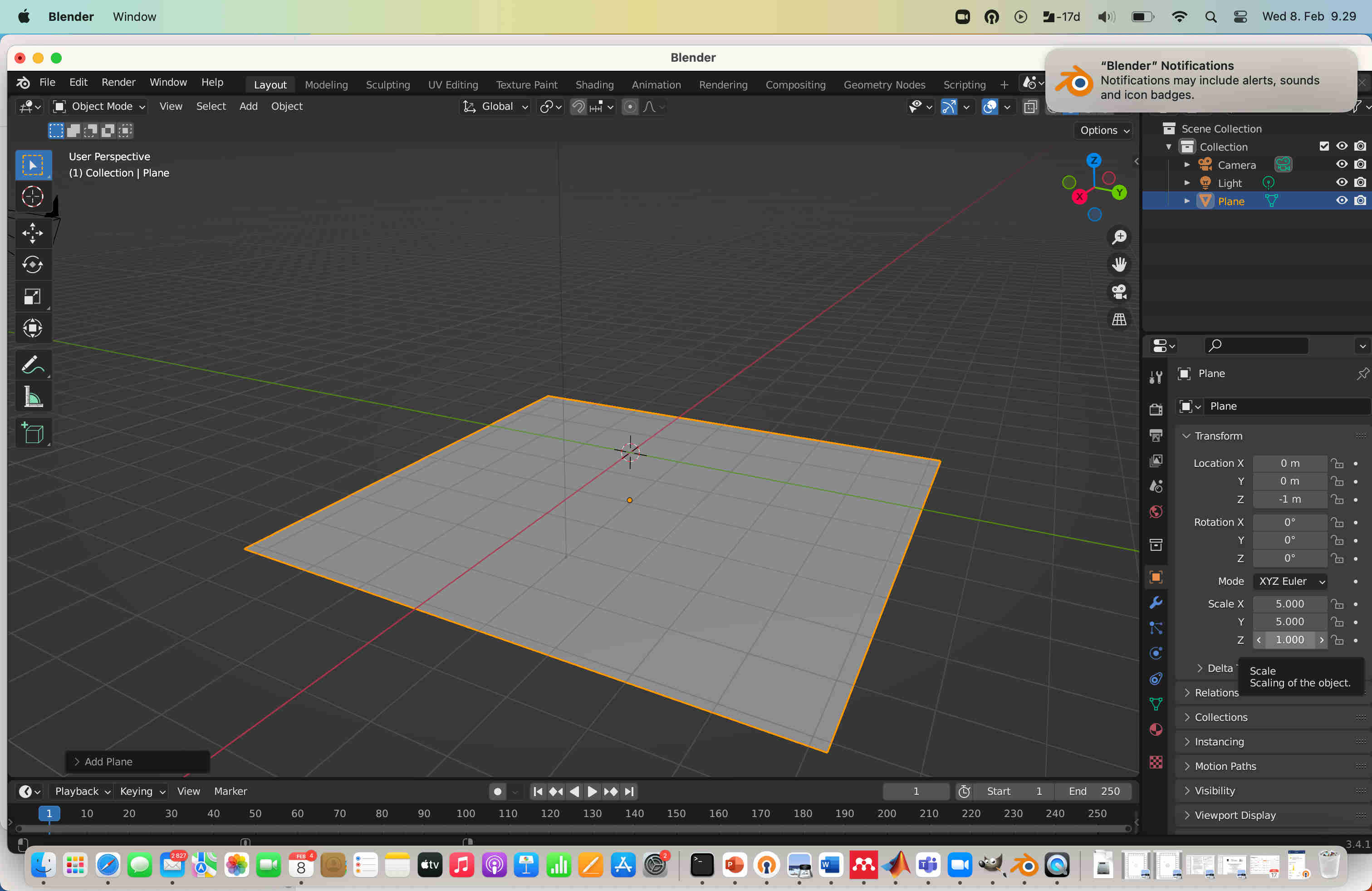
Then I re-sized the plane.
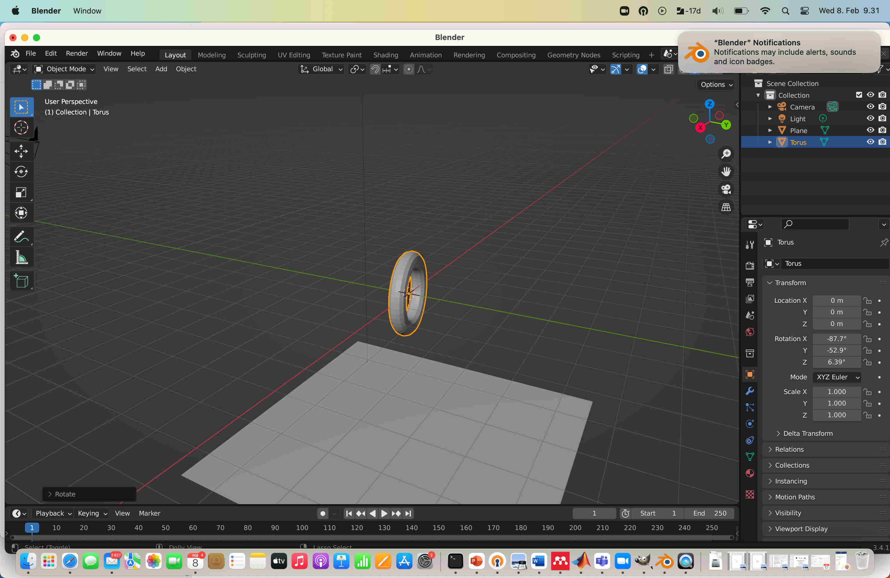
Then I added Torus to the scene using menu.

I set the plane as passive from the rigid body menu, so it would not drop down when the simulation is started.
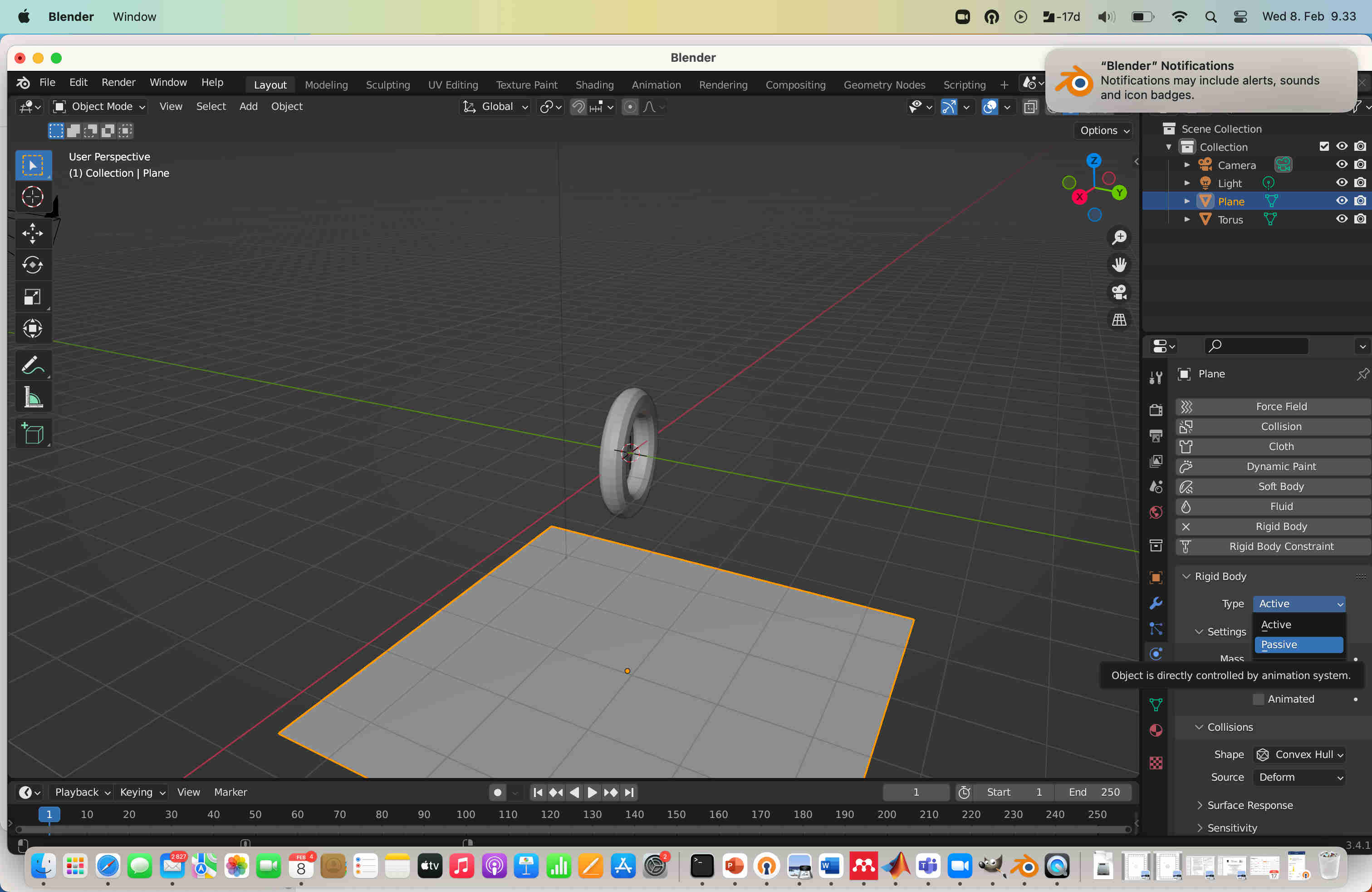
I checked that the torus is active in the rigid body menu, so it would drop down when the simulation is started.
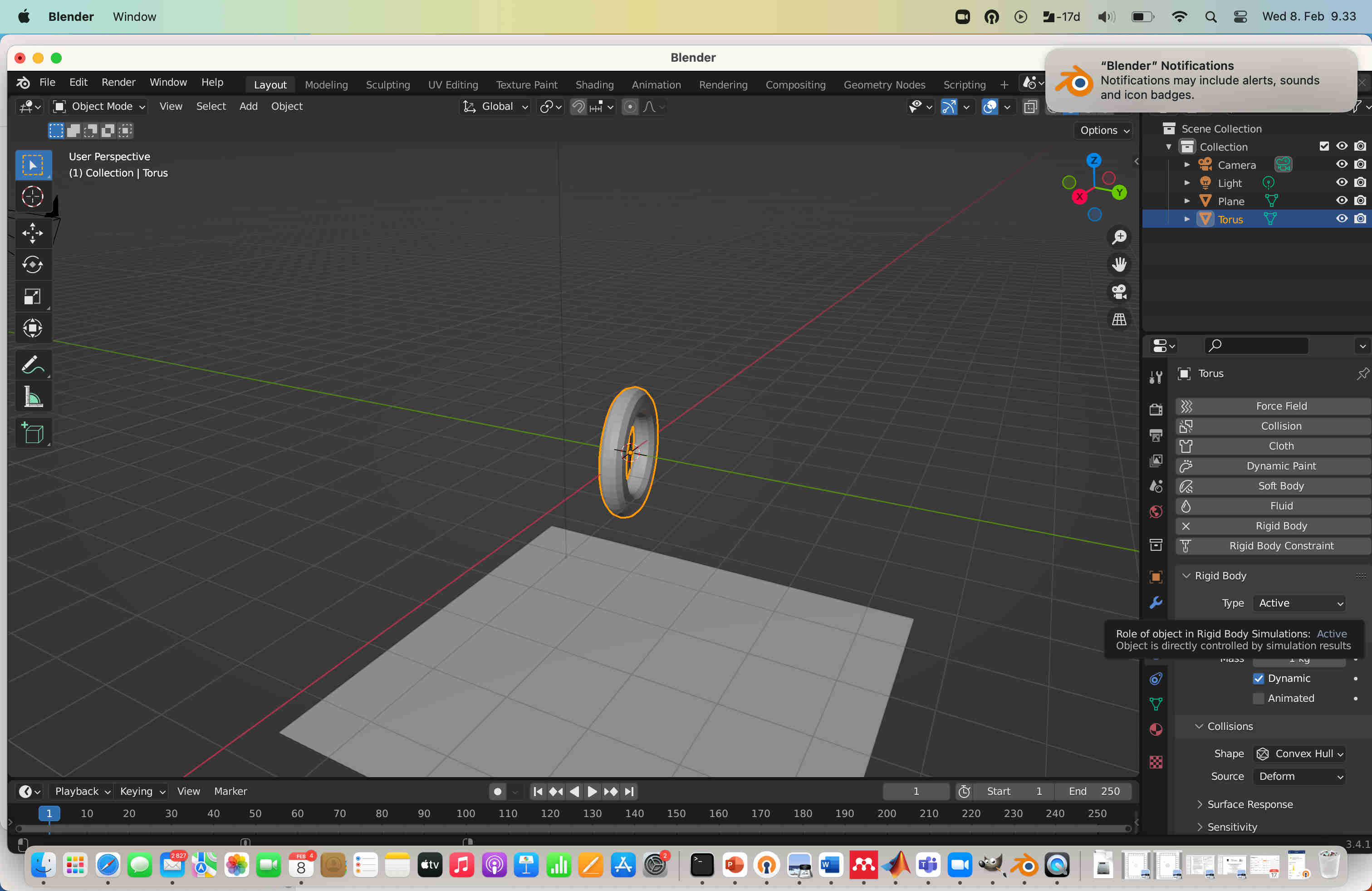
In the simulation, the torus dropped and collided with the plane.