4. Embedded programming
This week we experimented with microcontrollers.
Group work
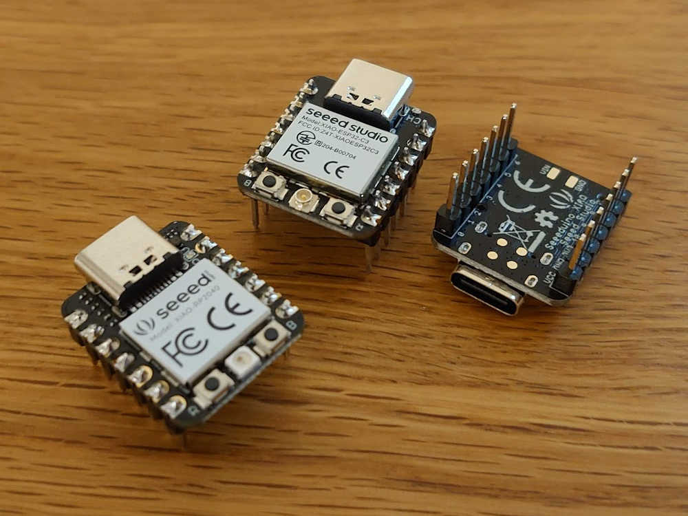
In this weeks group work we compared the SEEED XIAO boards with the chips RP2040, ESP32C3 and SAMD21.
In our group of three each one took responsibility of programming one board. For me it was the XIAO SAMD21. Everyone got one of the other boards but this one was shared with our group.
Programming for that was pretty straight forward unlike the RP2040, which I will use in later sections
For the SAMD21 we had difficulties finding the right pins but from that I learned where to find the schematic and therefore I will provide the links here:
I also learned that the SEEED XIAO boards have the same pin layout, so possibly the same code should have worked on all boards. However it could be that the C codes has some device specific stuff as it's supposed to be really optimized.
In the meantime the other group was using the oscilloscope we went ahead and started soldering the pin connectors to the boards. Here are the ones I soldered:
Using the oscilloscope was pretty new for me as I have only occasionally used one. How we wired the measurement circuit is described in the group work. It was interesting to use the oscilloscope for something practical but it's hard to say if I learned anything else from the process than the frequency differences/similarities of the boards. I also liked that the digital oscilloscope could save screenshots to a usb memory stick.
As a side note, I really like the idea of using these microcontrollers with the pin connectors. It's true that it makes things a lot easier but also it's so much more convenient. For example, if you make a circuit board with pin sockets and later want to make a new version you can use the microcontroller unit from the previous circuit board.
Reading a datasheet
I chose to use the XIAO RP2040 for the programming assignment. Preceding this, we were told to at least skim over the datasheet. The datasheet for RP2040 is quite long (600 pages) so I went through it but quickly skipped the pages that I didn't find meaninful or didn't care to understand.
Here are some takeaways from the datasheet:
- Leap year is skipped every 400 years which is not considered in the RTC (real time clock) of the RP2040. The next occurence would be 2100 so it's pretty safe but still some applications might need to consider that.
- The board can act as both USB host and a device. As I understand it could be possible to read and write a usb flash drive.
- The board also has a ring oscillator which is used during the initial boot as a clock.
- They also use the industry standard task management system:
Setting up
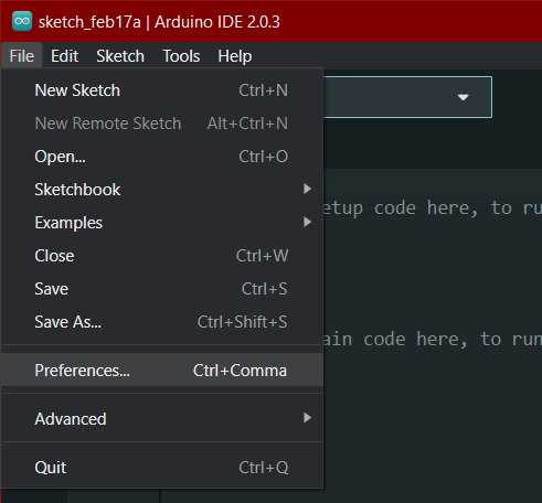
The very first thing to do was to install Arduino IDE 2.
Support for the boards
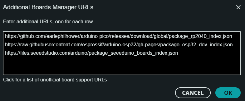
First we had to download the "cores" for Arduino IDE for each board to allow programming to those. The following links provide the required information for Arduino IDE:
https://github.com/earlephilhower/arduino-pico/releases/download/global/package_rp2040_index.json
https://raw.githubusercontent.com/espressif/arduino-esp32/gh-pages/package_esp32_dev_index.json
https://files.seeedstudio.com/arduino/package_seeeduino_boards_index.json
These links were just copied and pasted to board manager URL found from the preferences menu
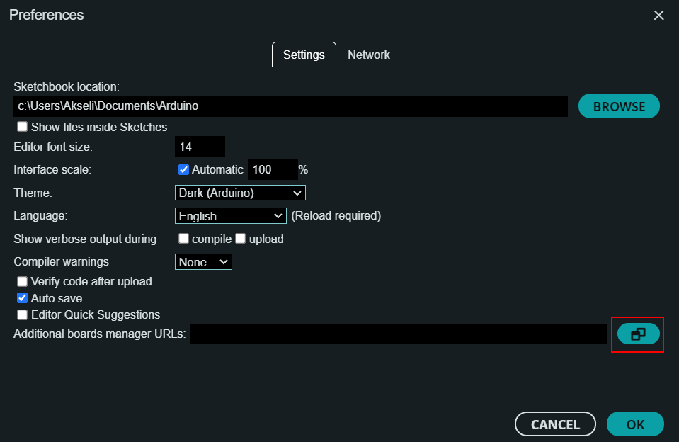
Paste the URLs here:
Boards manager
Next, the boards manager can be found from:
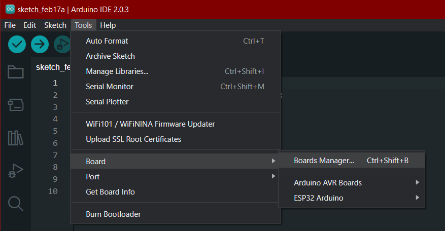
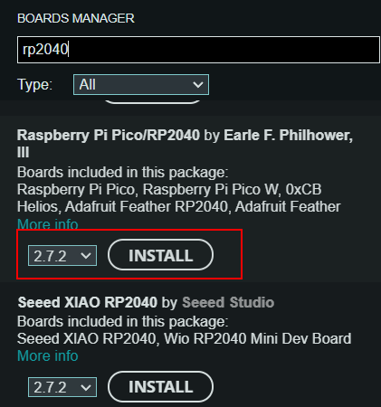
We were instructed to install this board package:
The packages I installed for the other two boards were:
- "esp23 by Espressif Systems"
- "Seeed SAMD Boards by Seeed Studio"
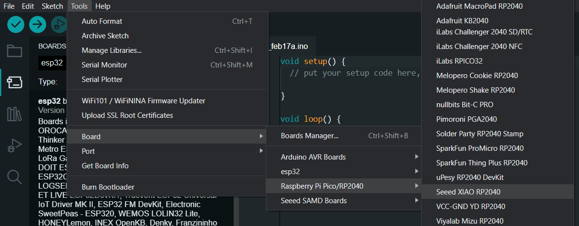
Selecting the board
When uploading code to a board need to select which board is used. Here are which selections I used for each board.
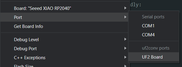
For RP2040:
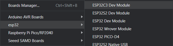
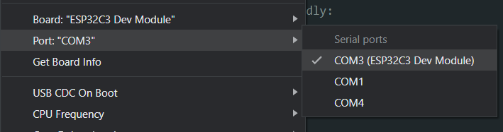
For ESP32C3:
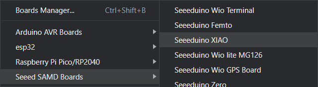
For SAMD21:
Connecting the boards
When I connected the boards two of them worked by just selecting the com port. Here is the selection for ESP32C3:
But for the RP2040 it needed to be put in the bootloader mode manually. To do this first hold boot (B) and then press reset (R). Then from the port selection select UF2:
Apparently this board (RP2040) also had some preprogrammed blinking demo:
Which stopped after putting it in the bootloader mode.
Programming the board
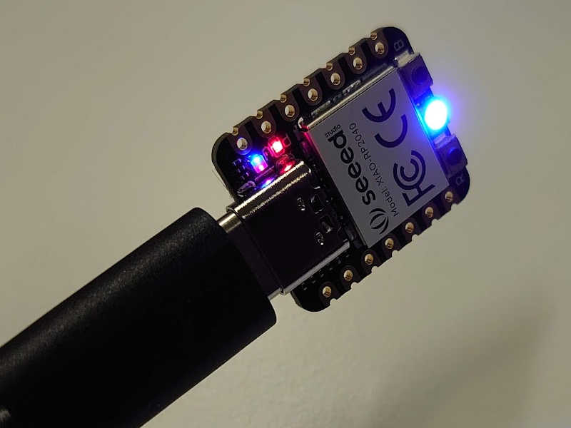
I chose to use the RP2040 because it has an integrated LED so I can focus on the programming and don't need any external components.
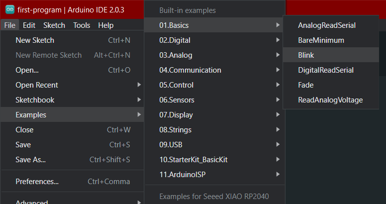
First program
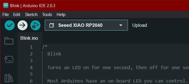
The Arduino IDE has some examples from which I tested uploading the program to a board using the blink example. It can be found like so:
It has the following code with very useful comments explaining it:
// the setup function runs once when you press reset or power the board
void setup() {
    // initialize digital pin LED_BUILTIN as an output.
    pinMode(LED_BUILTIN, OUTPUT);
}

// the loop function runs over and over again forever
void loop() {
    digitalWrite(LED_BUILTIN, HIGH);  // turn the LED on (HIGH is the voltage level)
    delay(1000);                      // wait for a second
    digitalWrite(LED_BUILTIN, LOW);   // turn the LED off by making the voltage LOW
    delay(1000);                      // wait for a second
}
The board appears to have multiple built-in LEDs in addition to the NeoPixel. If those can be controlled individually I might use the them as status indicators in the final project.
Press this arrow button to upload the code:
The Arduino IDE will first check that the code has correct syntax etc and then upload to the board. It will print something like this to the output console:
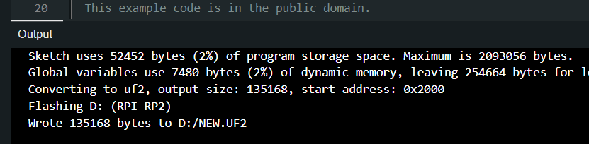
I did encounter error but when done right this does not happen:
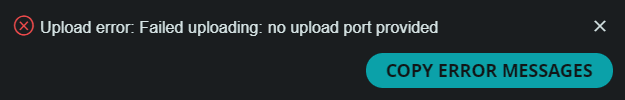
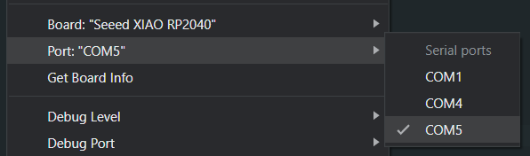
For this board I always have to select port UF2 when uploading as explained in previous section.
Further, I have to select com5 (in my case) after uploading to get the serial monitor to work.
Also I had the Arduino IDE being stuck on "uploading" and I had to restart the program after each upload.

I have no idea why this happens and it was only with the RP2040 board.
Maybe having the "upload port" selected for the serial monitor caused that issue.
NeoPixel on the XIAO RP2040
Next, I wanted to actually use the built-in NeoPixel. The NeoPixel is what is called an addressable LED. This means those can be connected in series and controlled individually with one single data pin.
I started with Adafruit NeoPixel example
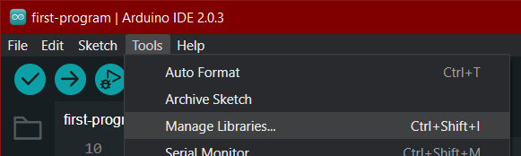
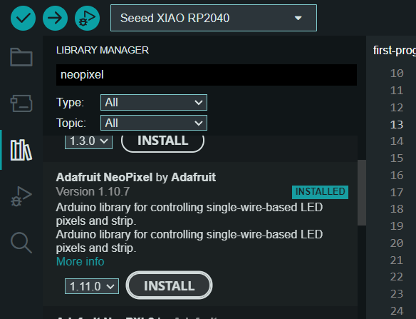
Installing library
To use the NeoPixel (easily) I need a library for it. I installed it according to these instructions.
Like this:
Search for "NeoPixel"
Finding the NeoPixel pin
So the next thing was to find which pin is the NeoPixel from this schematic.
We can see that the NeoPixel has actually two pins, NEO_PWR for the power, and NEOPIX for the data:
![]()
And here is where those pins are connected to the actual microcontroller chip:
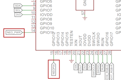
As we can see the pins are numbered 14 and 15, or GPIO11 and GPIO12. Which one to use in code? Who knows?
With the classic trial-and-error method I was able to determine, that the numbers to use in code are, in fact, 11 and 12. Therefore I could insert these definitions in my code:
#define NEOPOWERPIN 11 // Provides voltage for the built-in NeoPixel
#define NEOPIXELPIN 12 // Datapin for the the built-in NeoPixel
The #define is a macro that basically tells the compiler to replace for example "NEOPOWERPIN" with 11 when compiling.
So it's not an actual variable.
Controlling the NeoPixel
Firstly, this line in the example code initializes the NeoPixel:
And then this is done in the setup function:
void setup() {
    pinMode(NEOPOWERPIN, OUTPUT); // initialize digital pin NEOPOWERPIN as an output.
    digitalWrite(NEOPOWERPIN, HIGH); // Power for the NeoPixel

    pixels.begin(); //initialize the pixel
}
Now I can control the neopixel with pixels.setPixelColor()
but it needs something more so it goes like this:
    pixels.clear(); // Set all pixel colors to 'off'
    // We only have one pixel, therefore the first argument (index) is 0
    pixels.setPixelColor(0, pixels.Color(25, 25, 205)); // RGB color, I changed the values to nice blue
    pixels.show(); // Send the updated pixel colors to the hardware.
That can be used for example in the loop function with delay(1000); (delay in ms) to blink the NeoPixel.
Serial communication with the RP2040
Now the communication part. I will first describe the functions needed in code and after that go through whats to be done in Arduino IDE.
In code
In theory everything that is needed for serial communication are:
Initialize in the setup function:
To send information from the chip to the computer:
While sending information from the computer serial monitor can get more complicated this approach is still quite simple.
void loop() {
    String test_str; // Initialize the variable
    if (Serial.available() > 0) { // If there is incoming bytes in the serial:
        test_str = Serial.readString(); // This reads the serial buffer to a String
        Serial.println(test_str); // Send it back to see if it works
    }
}
If you don't mind using Strings instead of chararrays..
In Arduino IDE
There were some difficulties regarding the serial monitor in the Arduino IDE.
This was mainly due to needing to select the port UF2 as explained
previously.
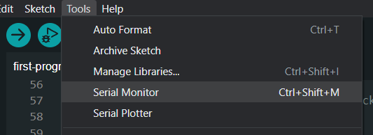
So this is after uploading the code to the board. First open the serial monitor from:
And I also had to select the correct port as the uploading was via UF2
but the communication was through COM5 in my case.
Then the serial monitor looks like this:
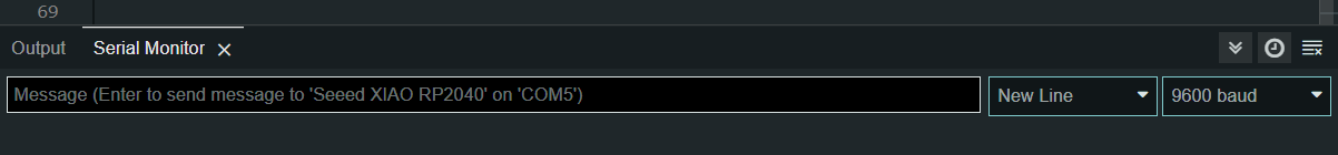
Make sure to check that the baud rate (here 9600 baud) is the same as defined in the code.
Result
So the code allows turning the blinking of the NeoPixel on/off via the serial communication.
Typing blink will activate the blinking and stop will turn it off.
I did however, leave the small built-in LED blinking anyways.
Here is a video demonstrating it in action:
Source code
So this is the resulting final code for this week:
Here is the same code as a code block as it is after
commit
f4fc39e9efe3dc015ae0577d4a27796811a74de1
End of week 4.