Week 8: Electronics Production
✓ characterize the design rules for your in-house PCB production process
✓ make and test the development board that you designed
Group assignment
Our group assignment can be found here.
The main outcomes and remarks of this week’s work were:
- The milling bits are very fragile and need to be handled with great care. Only a few mm drop could cause them to break.
- When using mods, instead of generating .rml files for the Roland CNC machine, we were generating g code, which can be read on all machines.
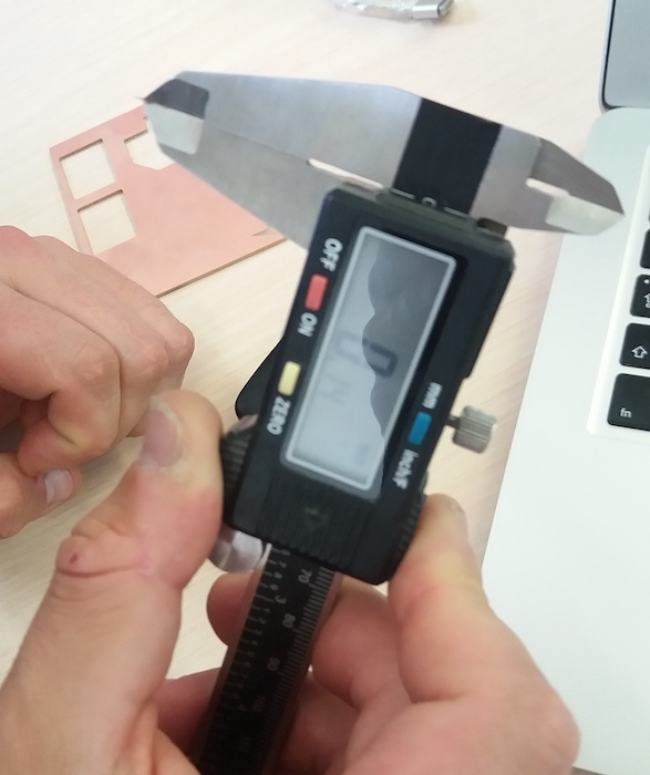
- The thickness of the copper layer is about 0.07 mm (0.14mm on the picture, because folded). We set the cut depth to 0.1mm to be safe:
- We had some problems with the MDF sacrificial table which wasn’t very flat. To fix this, we should have milled the whole table with a wide milling bit, but the week was so busy that we didn’t find the time to do it. During the regional review with Amsterdam and France, someone (I don’t remember who) said that he had so much problem with MDF that he switched to an acrylic table.
Producing my PCB
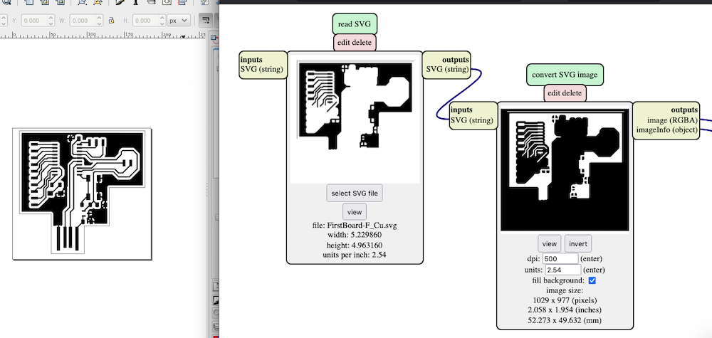
During the electronics design week, I used Kicad to draw a PCB circuit. At the end of the week, I also tried to export the design to .svg format and prepare the g-code with mods. However, when I went back to it, I realised that the svg doesn’t seem to import correctly in mods (svg on the left and mods on the right):
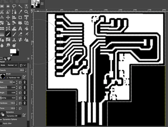
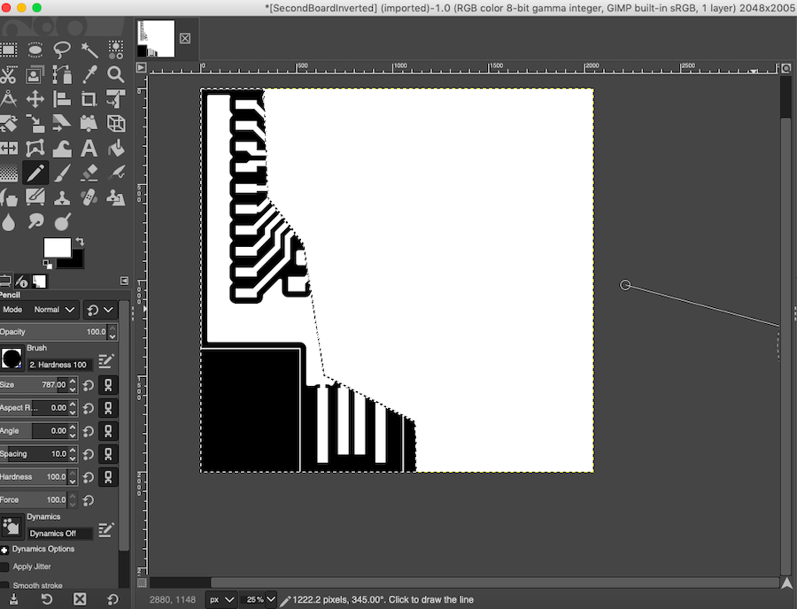
To solve this problem, I used the module for PNG. I had another issue when trying to invert the black and white: my picture was turning fully white. To prevent this, I used GIMP to invert the colors:
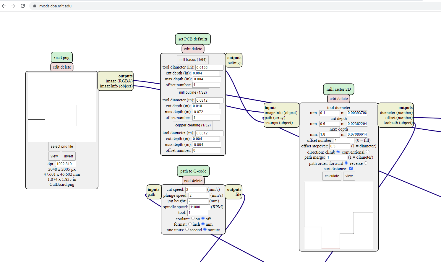
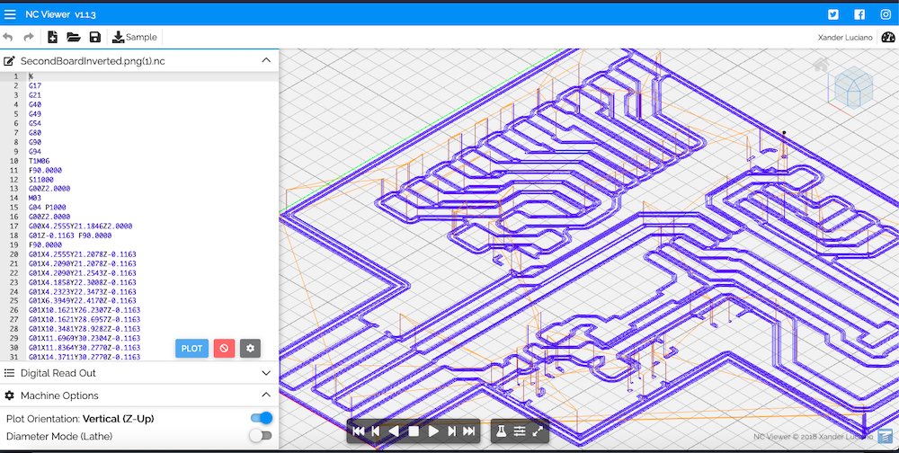
I could then process this image with mods following this tutorial from Aalto Fablab:
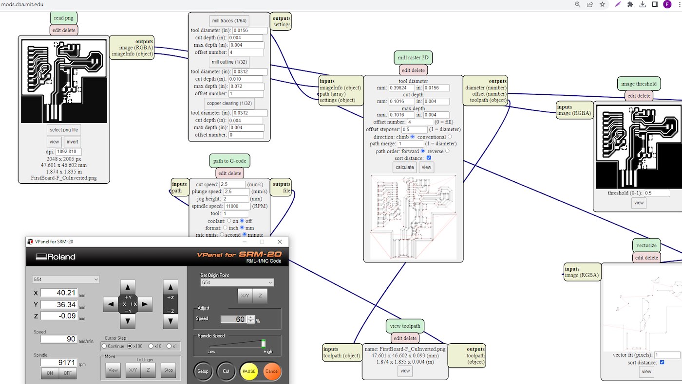
I only changed the tool diameter in the “mill Raster 2D” node to fit the one I had (1/64 inch). I should have changed the speed in the “path to G-Code” node according to the Aalto tutorial, but I forgot to do it. I fixed it with a quick hack: I reduced the speed in the VPanel software to 60%, which corresponds to 1.5mm/s.
After carving the PCB, I still needed to cut the board. For this task, I used the 1/32 inch mill. I had another problem with the png for the cutout: I didn’t pay attention to the line width when exporting and it was 0.1mm, so the g code generated with the correct tool diameter was empty. To fix this, I set the tool diameter to 0.1mm:
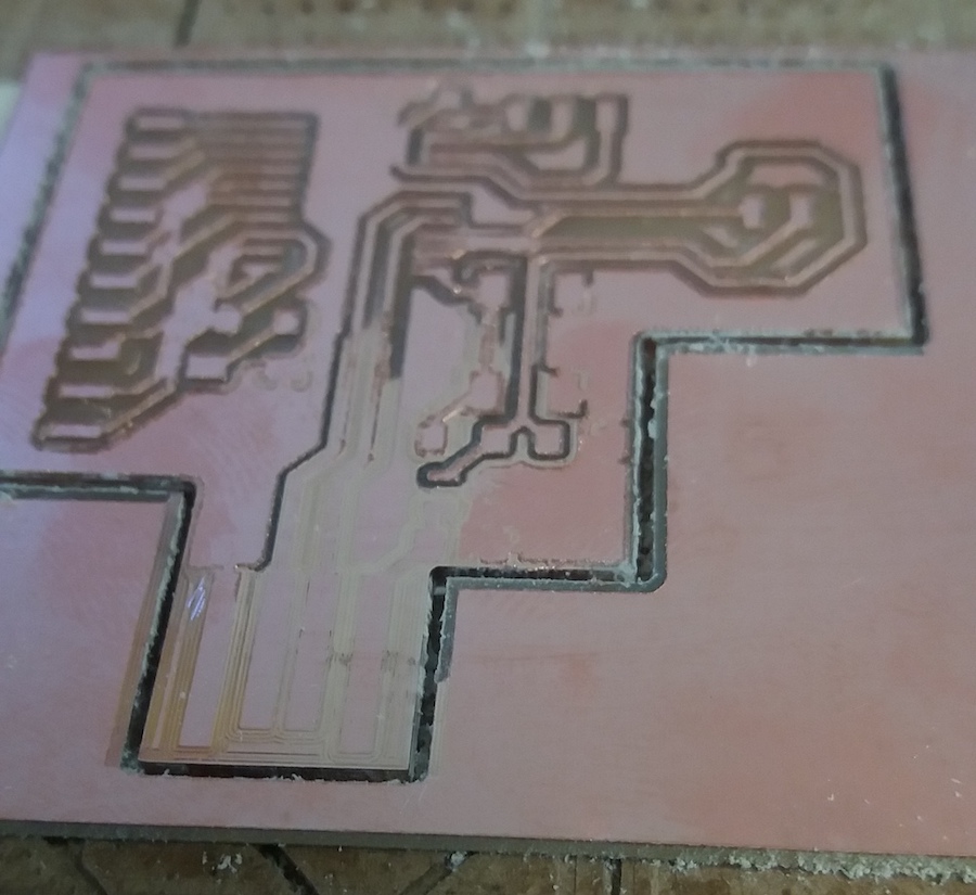
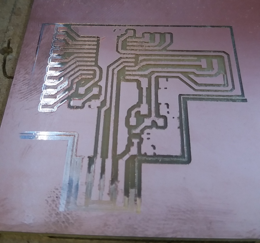
I could then launch the carving and cutting of my board. Unfortunately, the MDF table isn’t very flat. To flatten the table, we should have carved the whole surface with a large bit, but it would take hours and we were short on time.
This caused my first carve to fail. Some of the copper wasn’t removed properly:
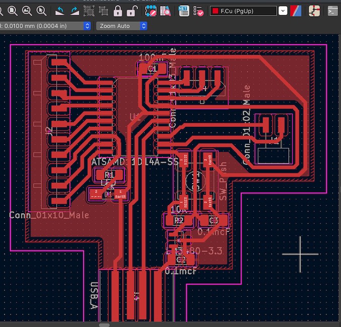
I didn’t notice it before taking the table out to clean the dust and therefore couldn’t carve it again (I lost the coordination system by moving the table). But anyway, some of the gaps were too narrow and the tool couldn’t go through some of the gaps. In order to prevent this, I redesigned all my paths, increasing the path clearance value, and changed their size from 0.4mm to 0.6mm:
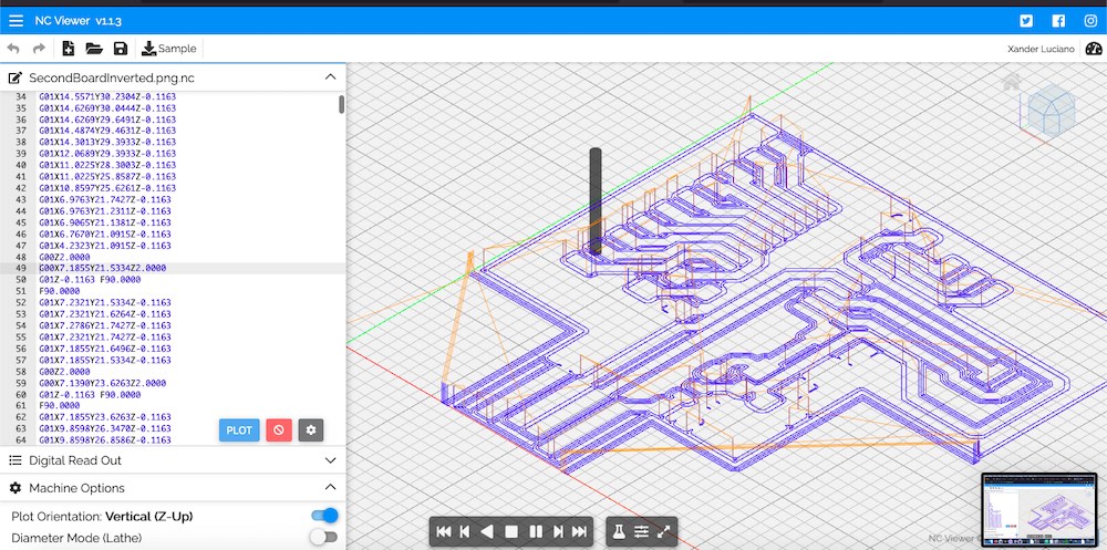
To make sure that the tool could go everywhere, I generated the g code twice: once with the correct tool size and once with a much smaller tool size (0.1mm). Then, I used a tool to visualize my g code and compare my two toolpaths to see if some important part is missing:
For my next trial, I had the same problem with the uneven table level, but this time I didn’t move it before cleaning the dust:
I didn’t want to carve again the whole surface, so I edited my png image in GIMP to carve only the missing part:
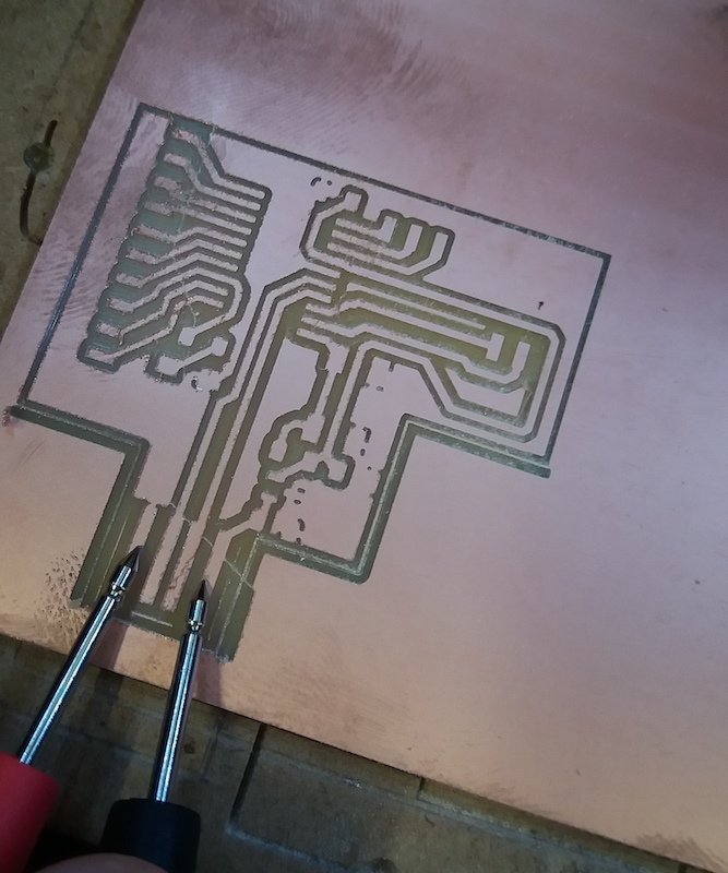
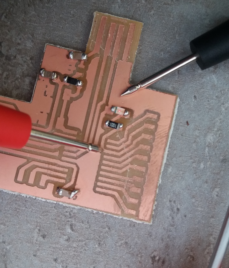
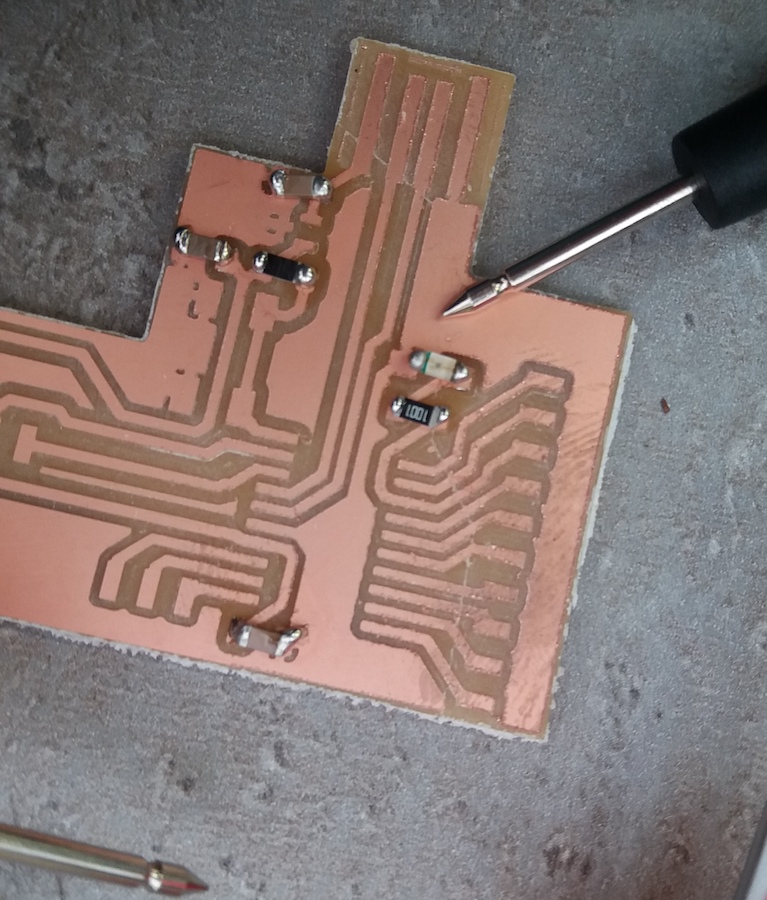
Then I set the zero a bit lower and launched the job. It worked! I tested my board for short circuits with a multimeter:
Soldering the components
I then started the soldering. I first watched some tutorial to understand the technique. It was a really tedious task and I found out that my hands are not steady at all. After a lot of efforts, I managed to solder few components. I used a multimeter to test in which direction I should solder the LED and then test if it was correctly soldered:
After a couple of hours, I finally had all my components soldered:
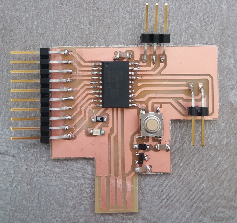
During the review with Oulu, Jani told me that it was bad practicie to have “balls” of solder. I tried to fix it but it was really not that easy and I was afraid to create more problems, so I thought that I would do it better next time…
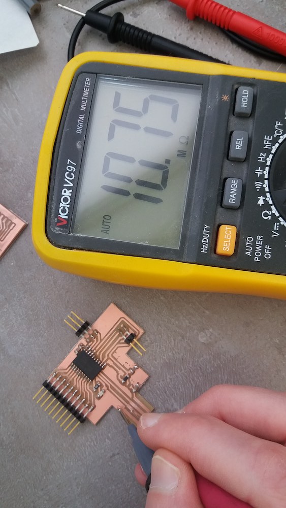
I used the multimeter to do a quick check of the connection and to see if there were some obvious short circuits:
Programming the board
To try to program my board, I followed the documentation of Onik Babajanyan from last year and also the one from Chloé Laurent. They refered to these explanations on gitlab.fabcloud that I tried to follow. It was quite hard, since the programmer I had didn’t have the same spatial configuration than the one from the explanations. I had to match and follow the pins from the MCU to understand which connection to make with my board:
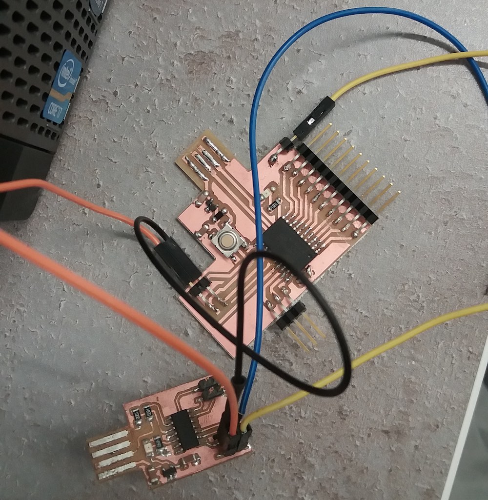
When trying to connect my board, I noticed that I missed a GND pin and a Reset pin, so I added them as a very quick and dirty fix.
Since my MacBook doesn’t have two USB ports next to each other, I decided to flash my board on a desktop computer which is running Linux. I could follow then the procedure that Chloé details:
- Download the source for edbg
- Install the requirement libudev-dev with apt-get
- Move to the source folder and type:
make all - Download the corresponding dap binary
- Flash the board in the same folder as the dap .bin file:
sudo edbg -ebpv -t samd11 -f dap_file_name.bin
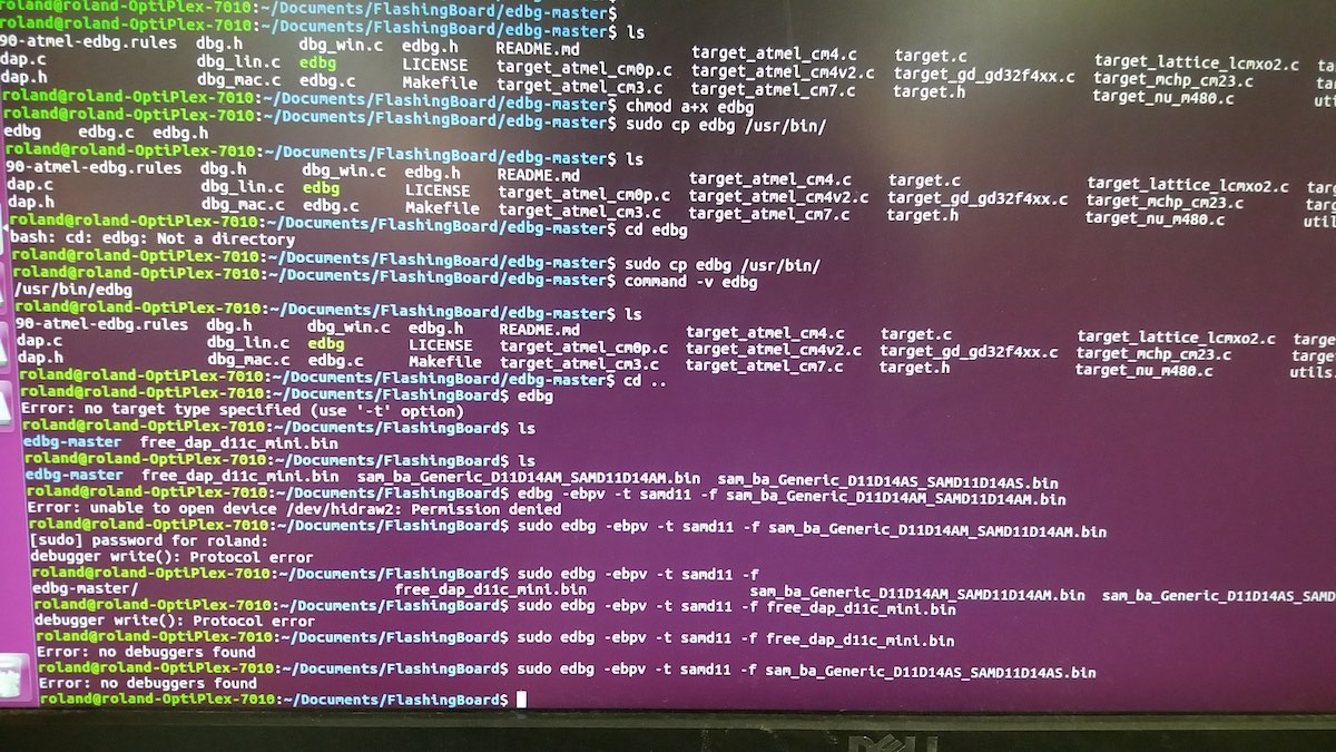
Since I had a different version of MCU, I wasn’t sure which dap file I should use. I tried few versions, but none worked, and I don’t know if it has anything to do with the dap file:
When I tried again another day, as the computer with Linux was busy, I tried to install edbg on Windows but had exactly the same error. As I saw in these explanations that an alternative program could be used if it wouldn’t work on MacOS, I tried to install openocd on Windows. I downloaded and unzipped the folder with the openocd executable following these instructions. I then adapted the config file and downloaded the dap file corresonding to my board
openocd.cfg:
interface cmsis-dap
set transport swd
set CHIPNAME atsamd11d14a
source [find target/at91samdXX.cfg]

init
targets
reset halt
at91samd bootloader 0
program sam_ba_Generic_D11D14AS_SAMD11D14AS.bin verify
at91samd bootloader 4096
reset
shutdown
Then I ran openocd.exe and I got some “ Verified OK ”:
C:\Users\fab\Documents\FlashingPCB\openocd-20230111\OpenOCD-20230111-0.12.0\bin>openocd.exe
Open On-Chip Debugger 0.12.0 (2023-01-11) [https://github.com/sysprogs/openocd]
Licensed under GNU GPL v2
libusb1 09e75e98b4d9ea7909e8837b7a3f00dda4589dc3
For bug reports, read
        http://openocd.org/doc/doxygen/bugs.html
DEPRECATED! use 'adapter driver' not 'interface'
Info : auto-selecting first available session transport "swd". To override use 'transport select <transport>'.
Info : CMSIS-DAP: SWD supported
Info : CMSIS-DAP: FW Version = v0.1
Info : CMSIS-DAP: Serial# = D3116B39
Info : CMSIS-DAP: Interface Initialised (SWD)
Info : SWCLK/TCK = 1 SWDIO/TMS = 1 TDI = 0 TDO = 0 nTRST = 0 nRESET = 1
Info : CMSIS-DAP: Interface ready
Info : clock speed 400 kHz
Info : SWD DPIDR 0x0bc11477
Info : [atsamd11d14a.cpu] Cortex-M0+ r0p1 processor detected
Info : [atsamd11d14a.cpu] target has 4 breakpoints, 2 watchpoints
Info : starting gdb server for atsamd11d14a.cpu on 3333
Info : Listening on port 3333 for gdb connections
Error: [atsamd11d14a.cpu] clearing lockup after double fault
Polling target atsamd11d14a.cpu failed, trying to reexamine
Info : [atsamd11d14a.cpu] Cortex-M0+ r0p1 processor detected
Info : [atsamd11d14a.cpu] target has 4 breakpoints, 2 watchpoints
[atsamd11d14a.cpu] halted due to debug-request, current mode: Thread
xPSR: 0xa1000000 pc: 0xfffffffe msp: 0xfffffffc
[atsamd11d14a.cpu] halted due to debug-request, current mode: Thread
xPSR: 0xa1000000 pc: 0xfffffffe msp: 0xfffffffc
** Programming Started **
Info : SAMD MCU: SAMD11D14ASS (16KB Flash, 4KB RAM)
** Programming Finished **
** Verify Started **
** Verified OK **
shutdown command invoked
Info : Listening on port 6666 for tcl connections
Info : Listening on port 4444 for telnet connections
However, I also had some error on these lines:
Error: [atsamd11d14a.cpu] clearing lockup after double fault
Polling target atsamd11d14a.cpu failed, trying to reexamine
I typed edbg --list and it recognized the programmer board, but not mine,
and I don’t really know if it should recognize it or if it only recognizes programmer
boards.
I tried again later to run openocd.exe and it didn’t show this error:
C:\Users\fab\Documents\FlashingPCB\openocd-20230111\OpenOCD-20230111-0.12.0\bin>openocd.exe
Open On-Chip Debugger 0.12.0 (2023-01-11) [https://github.com/sysprogs/openocd]
Licensed under GNU GPL v2
libusb1 09e75e98b4d9ea7909e8837b7a3f00dda4589dc3
For bug reports, read
        http://openocd.org/doc/doxygen/bugs.html
Info : auto-selecting first available session transport "swd". To override use 'transport select <transport>'.
Info : CMSIS-DAP: SWD supported
Info : CMSIS-DAP: FW Version = v0.1
Info : CMSIS-DAP: Serial# = D3116B39
Info : CMSIS-DAP: Interface Initialised (SWD)
Info : SWCLK/TCK = 1 SWDIO/TMS = 1 TDI = 0 TDO = 0 nTRST = 0 nRESET = 1
Info : CMSIS-DAP: Interface ready
Info : clock speed 400 kHz
Info : SWD DPIDR 0x0bc11477
Info : [atsamd11d14a.cpu] Cortex-M0+ r0p1 processor detected
Info : [atsamd11d14a.cpu] target has 4 breakpoints, 2 watchpoints
Info : starting gdb server for atsamd11d14a.cpu on 3333
Info : Listening on port 3333 for gdb connections
[atsamd11d14a.cpu] halted due to debug-request, current mode: Thread
xPSR: 0x81000000 pc: 0x000004a0 msp: 0x20000ffc
[atsamd11d14a.cpu] halted due to debug-request, current mode: Thread
xPSR: 0x81000000 pc: 0x000004a0 msp: 0x20000ffc
** Programming Started **
Info : SAMD MCU: SAMD11D14ASS (16KB Flash, 4KB RAM)
** Programming Finished **
** Verify Started **
** Verified OK **
shutdown command invoked
Info : Listening on port 6666 for tcl connections
Info : Listening on port 4444 for telnet connections
However, my device was still not recognized by the computer. I tried to check some of the connections, I added some solder to the USB port and suddenly, out of nowhere, my device was recognized by Windows.
To try programming it, I followed the steps described here:
- Go to Arduino -> Preferences -> Additional Boards Manager URLs
- Add https://www.mattairtech.com/software/arduino/package_MattairTech_index.json
- Go to Tools -> Board -> Boards Manager
- Install the “MattairTech SAM D|L|C Core for Arduino” package
After this, I was able to select the port for my device in Arduino IDE. Unfortunately, when trying to upload the default program, I had an error:
SAM-BA operation failed an error occured while uploading the sketch
After few trials, and after trying to plug my device again, it was not recognized anymore. I don’t really know what could be the problem. My hypothesis is that there is some connection problem with the pins used by the USB, but I checked them and they seem fine.
The next day, I tried again to flash the bootlader, and I had the following error:
at address 0x0 expected 0xfc, read 0xff. Error: verification failed
I was very puzzled by this error, but fortunately, Babken, my instructor, suggested me to take a look at Adrian Torres’ page where he reported and fixed this error. Using his fix, I was able to correct my error:
edbg-windows-r24.exe -b -t target_type -F w,2:0,7
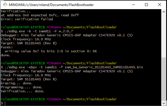
My board was then recognized by the computer and by the Arduino IDE. I was very happy and ready to upload a simple blinking program to my board:
void setup() {
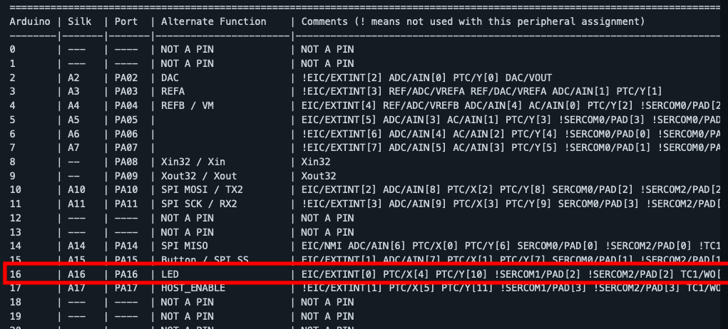
pinMode(16, OUTPUT);
}
void loop() {
digitalWrite(16,HIGH);
delay(1000);
digitalWrite(16,LOW);
delay(1000);
}
In order to understand the pin mapping from Arduino to SAMD11D14, I used this documentation:
Unfortunately, I had another error when uploading my sketch:
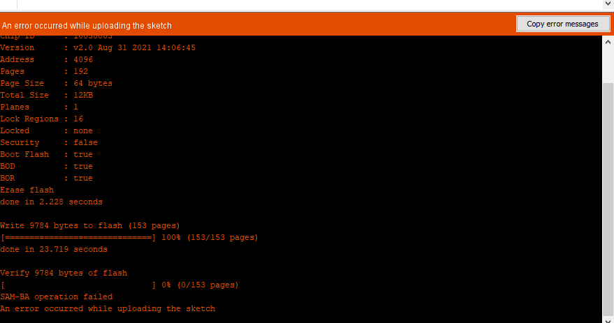
I searched on the Fabacademy website to see if anyone else had had this error and, luckily, I found someone: Lindong Huang. He had this error about 40% of the time and for me it was 100%. He was dealing with this error in the following way:
“
- Bash the “hard reset” button on my board a couple times
- Disconnect and reconnect the USB hub
- Disconnect USB, trick Arduino into uploading the sketch into thin air (and failing), reconnect USB, upload sketch again
- Panic, and retry in a minute
“
I used the same approach as him, and after some time, I realised I just needed to press the “Reset” button once the sketch failed uploading to almost always fix this issue.
And here it is:
Conclusion
During this week, I finally found out if what I designed two weeks ago would have worked… well, it wasn’t good. I was amazed by how clueless I was when designing my board. For example, I forgot to add a pin header for the Ground pin, which is probably one of the most used pins. I made many mistakes like this. Some components seemed to be an overkill to add when designing my board (like the LED that lights up when the board is powered) but were painfully missing once I was trying to actually use my board.
Files of the week
PNG and SVG files for carving and cutting the board