Week 7: Computer-Controlled Machining
✓ do your lab’s safety training
✓ test runout, alignment, fixturing, speeds, feeds, materials, and toolpaths for your machine
✓ make (design+mill+assemble) something big (~meter-scale)
Group assignment
Here is the link to the group assignment.
First, we learnt about how to operate the CNC machine safely. This was important to me since I was quite intimidated by the Shopbot.
We had some surprise when cutting our square, since it was a bit smaller than the expected size. We thought that the runout could cause this. But when we measured our pocket, it was also smaller than expected. If it would be caused by the runout, it should have been bigger.
We didn’t know what would cause this discrepancy, but during the regional review with Jani, he gave us a great insight regarding the seemingly awkward sizes we obtained: the smaller size of the square cut from the outside and the pocket wasn’t related to the outrun of the mill, but to a scaling issue of the software.
Making something big: a failed attempt
Design
For this week, I made a big mistake by spending too much time thinking about an idea for the design. I came up quite quickly with the idea of cutting some kind of 2D shape inside a circle. I made few trials like this one:
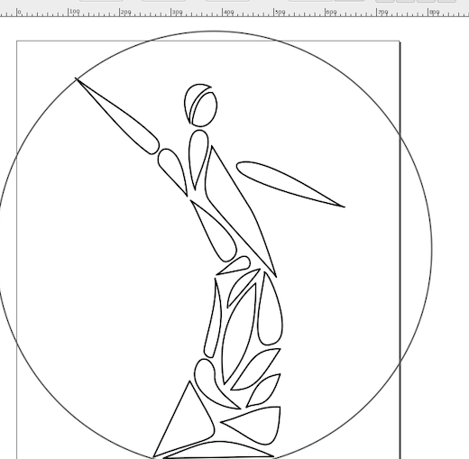
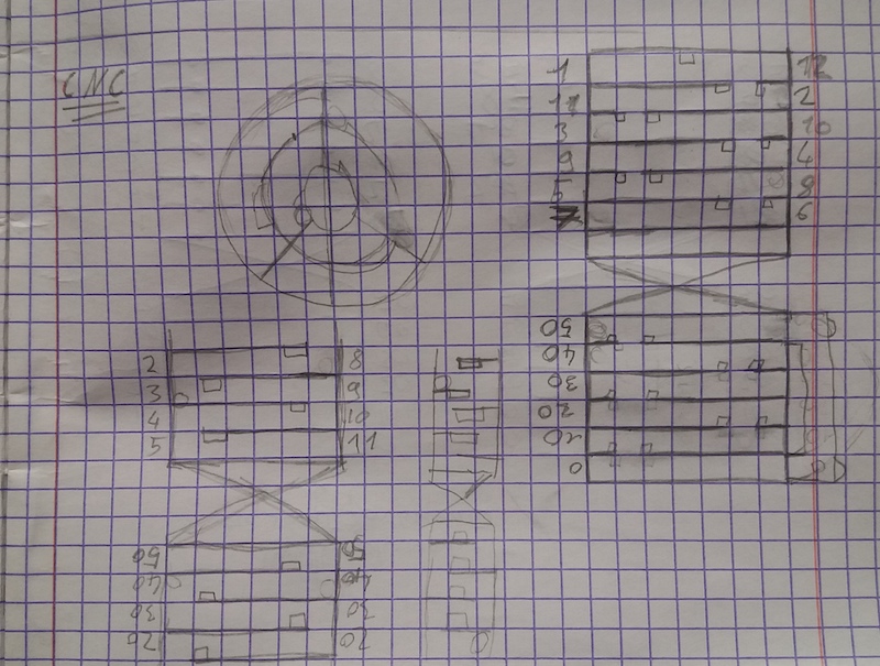
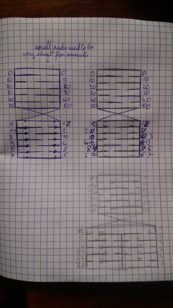
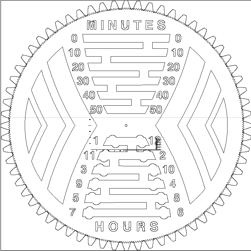
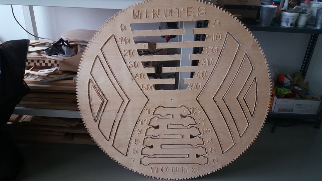
For this one, I thought of connecting the loose parts with some metal wire, but gave up on this idea. After a lot of time, I finally settled for some kind of clock: two spherical or cylindrical markers would show the minutes and hours. In order to understand how to reach this goal, I made several sketches:
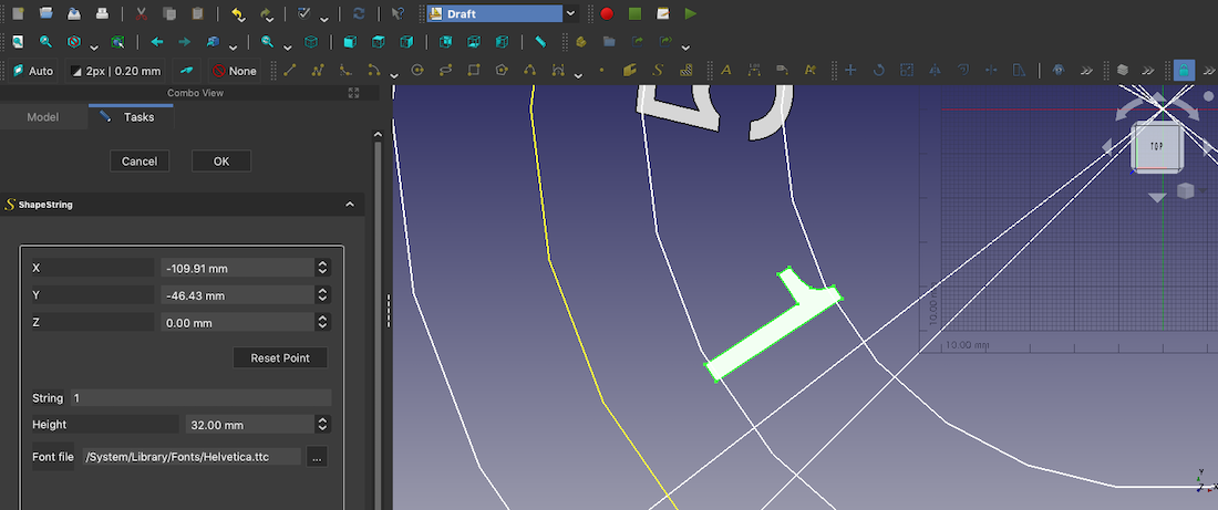
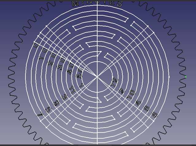
Once I had a better idea of what I wanted to make, I started designing using FreeCAD. Since I knew I needed to write numbers with this software, I started by watching a youtube tutorial explaining this. I then tried to put it into practice:
My computer is quite old and working with numbers is pretty painful in Freecad, since everytime I insert a number, the calculation takes a long time.
After a lot of efforts, I finally managed to have most of the numbers ready:
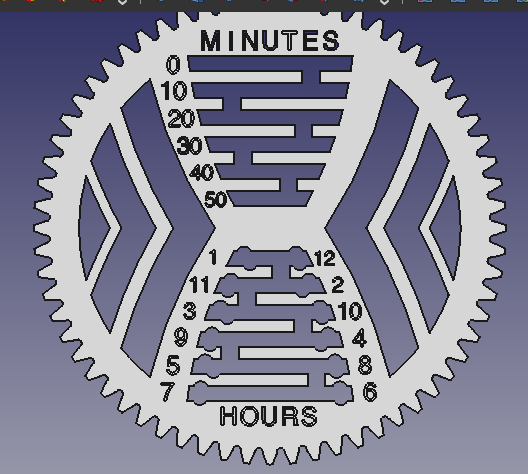
It was unfortunately not finished, and it was so slow to work like this that I decided to remake the gear and number inside Inkscape. So I exported the design using the TechDraw workbench:
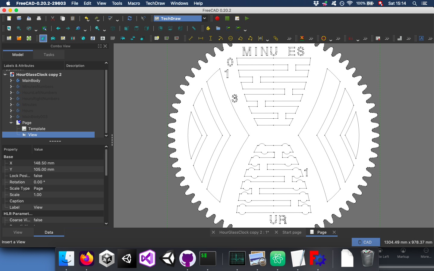
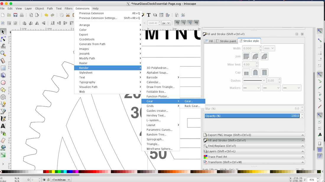
In Inkscape, I made the gear using the extension found in Extension -> Render -> Gear.
My design needed a bit of cleaning, but I would do it inside Vcarve pro:
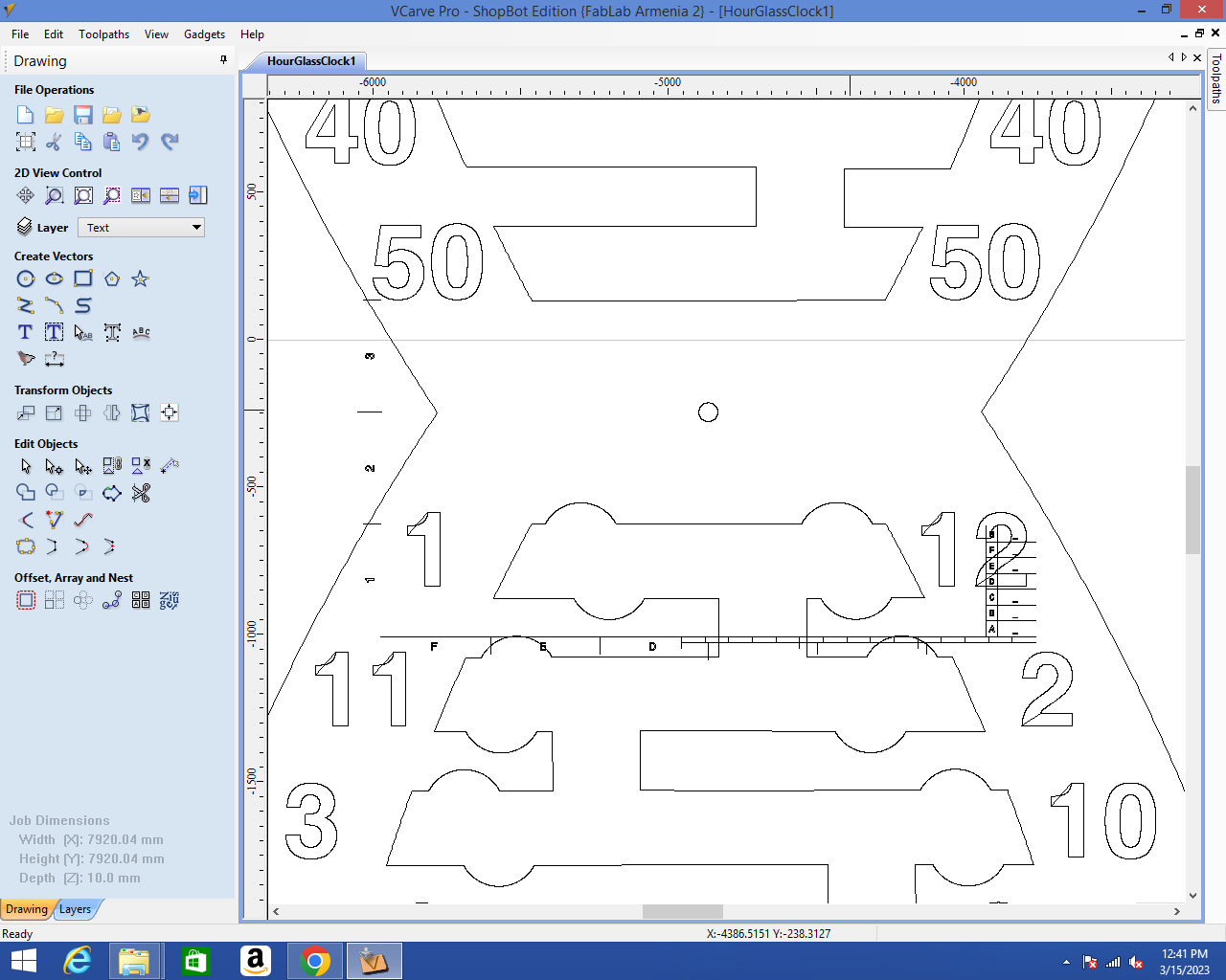
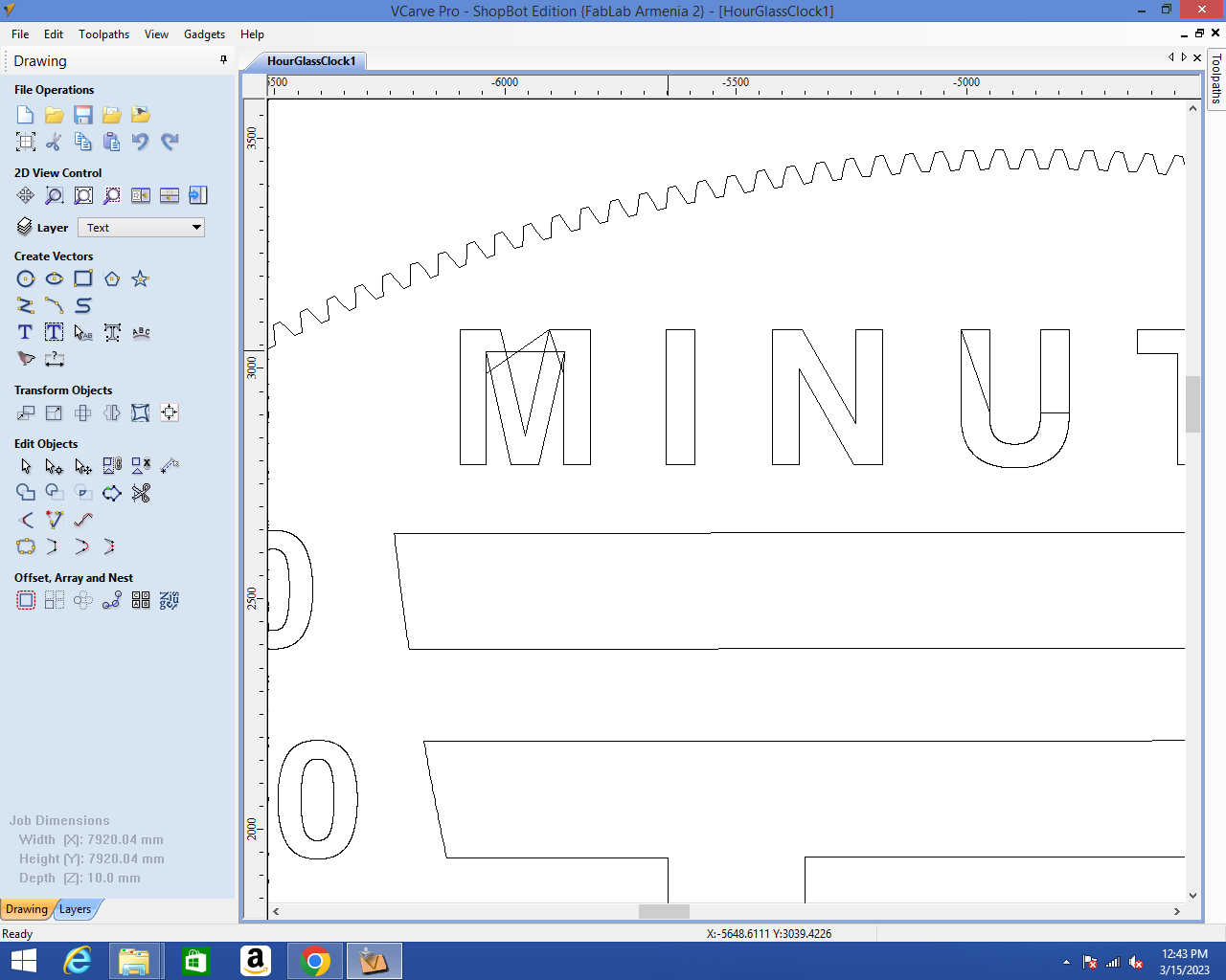
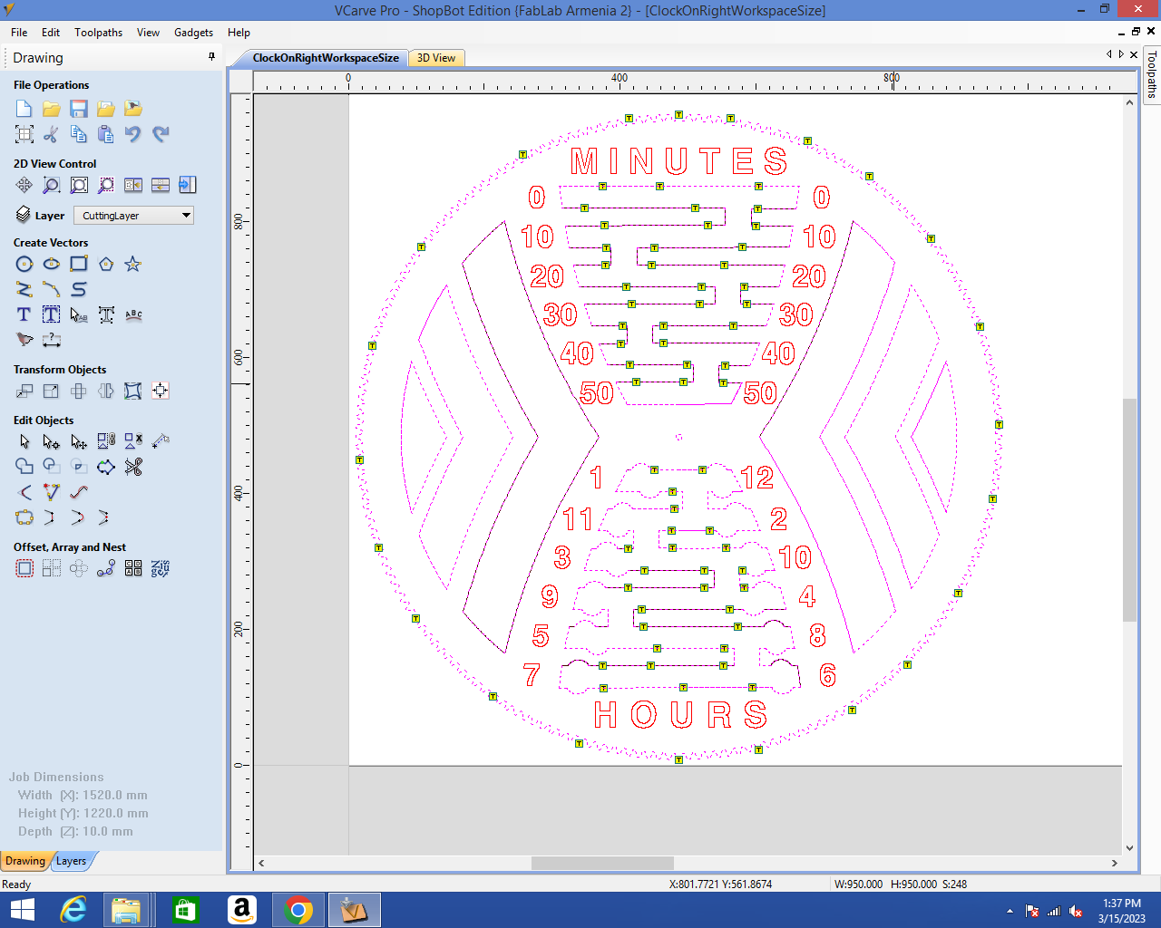
After I edited the design in Inkscape, I exported it to .dxf. I could then import it inside Vcarve pro on the computer connected to the Shopbot:
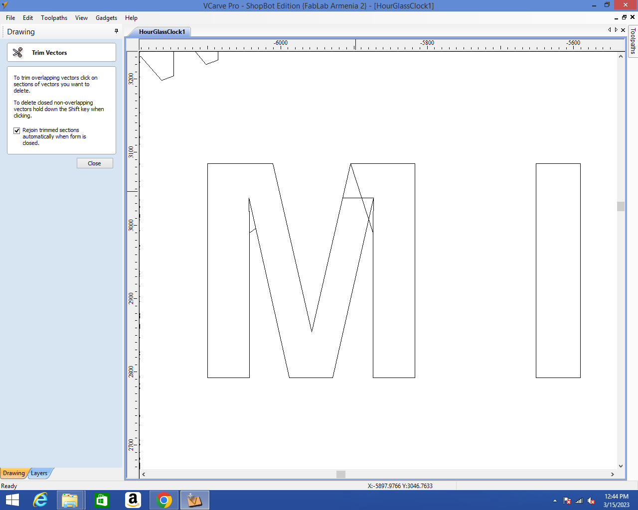
I had a lot of cleaning to do. The Trim Vectors tool was very handy for this task:
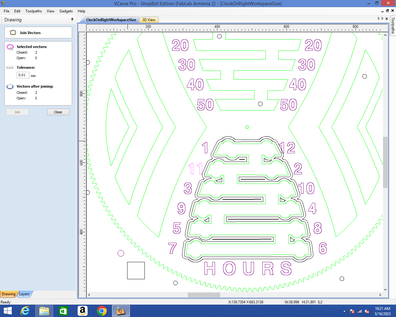
The Join Vectors tool was also very useful, since most of the vectors were not joined:
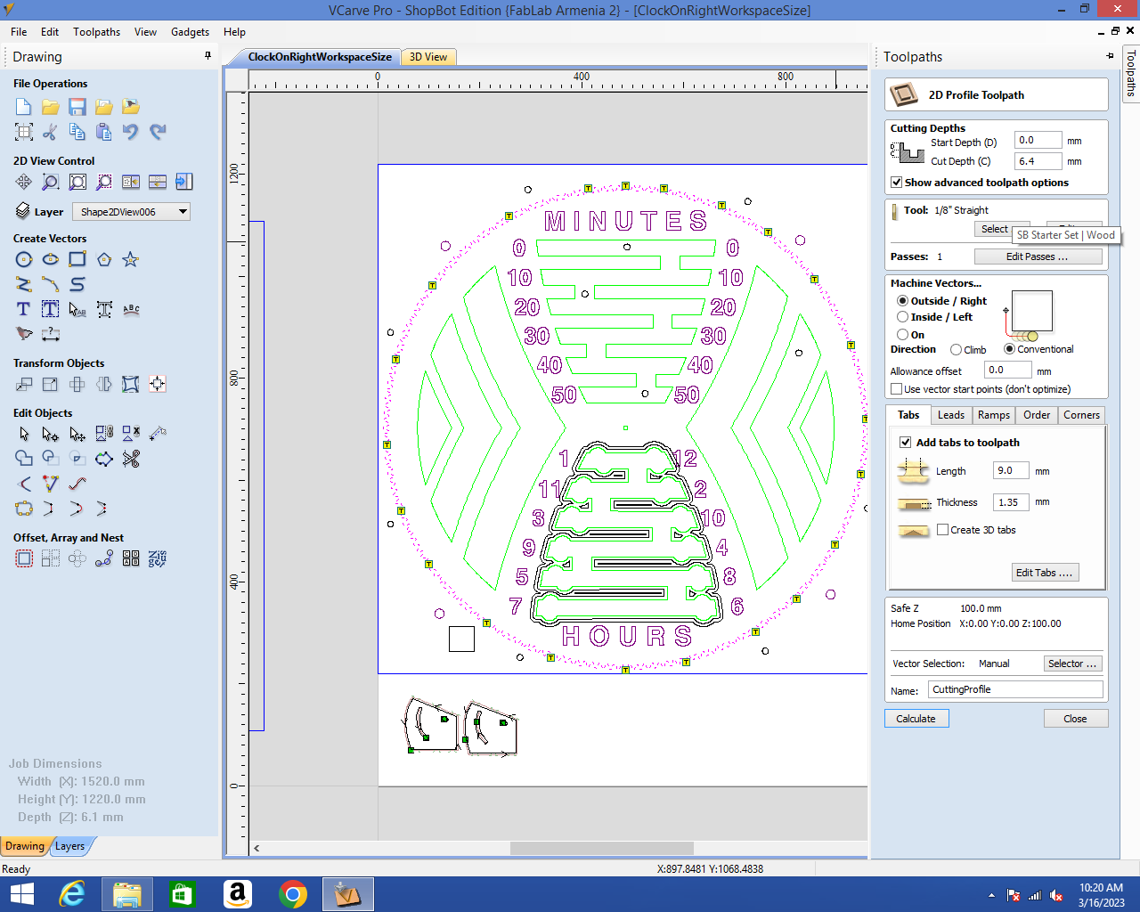
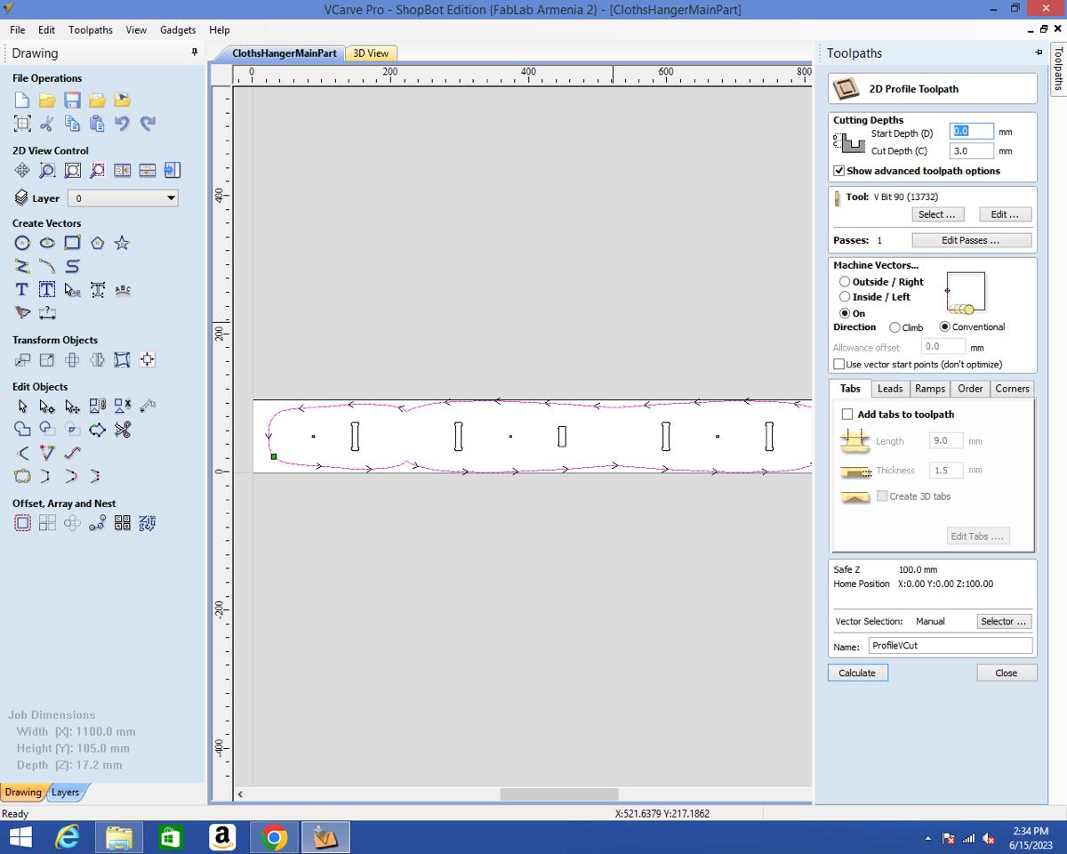
I used the 2D profile toolpath in order to define the toolpath for cutting:
I added tabs to keep my part attached to the frame until the end. If possible, I added them along the wood fiber so that they would be easier to detach.
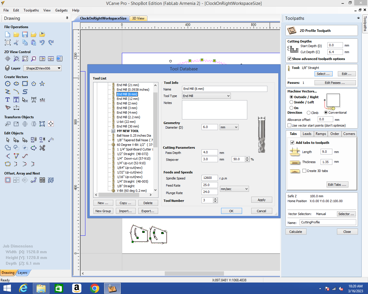
I selected the tool I would use to cut my part: 6mm upcut endmill.
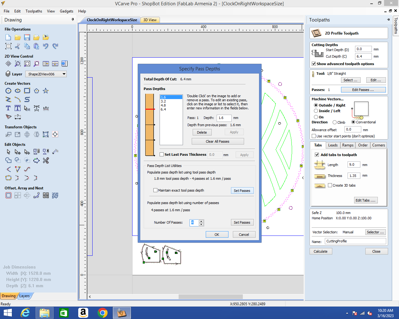
I could then edit the number and the depth of the passes:
Cutting
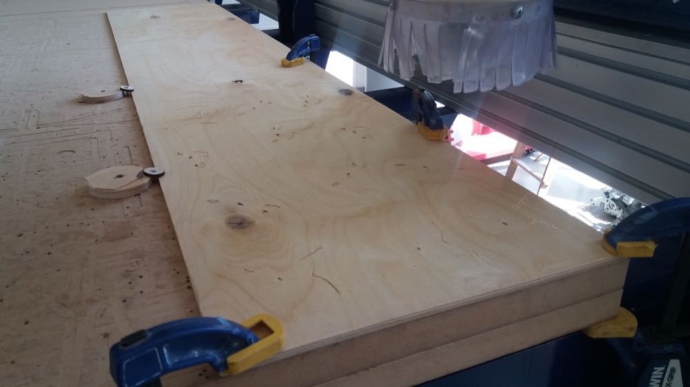
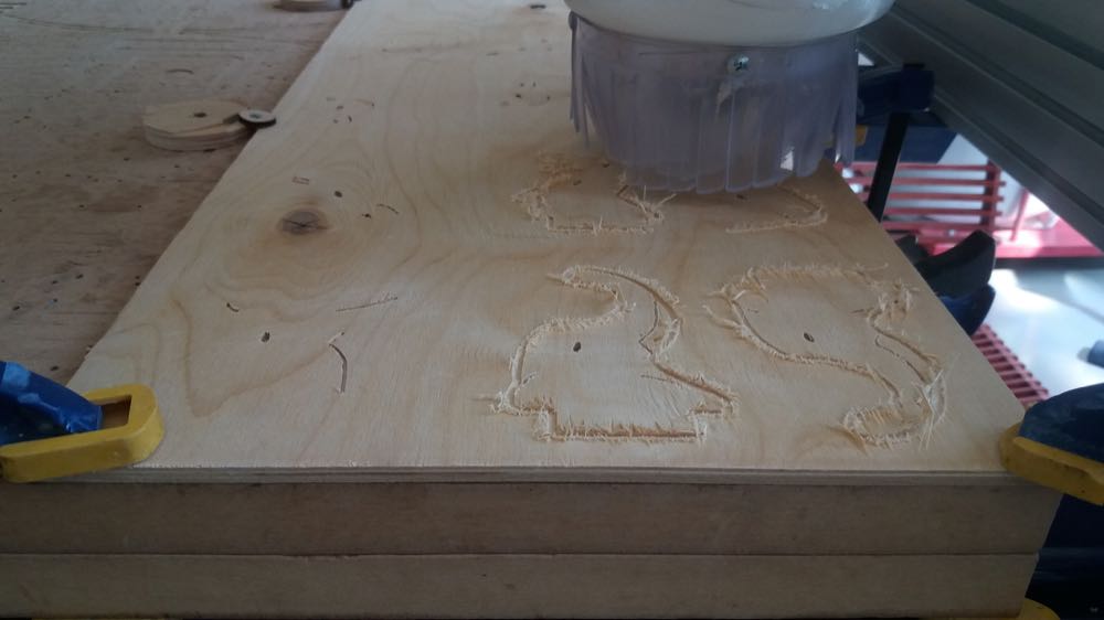
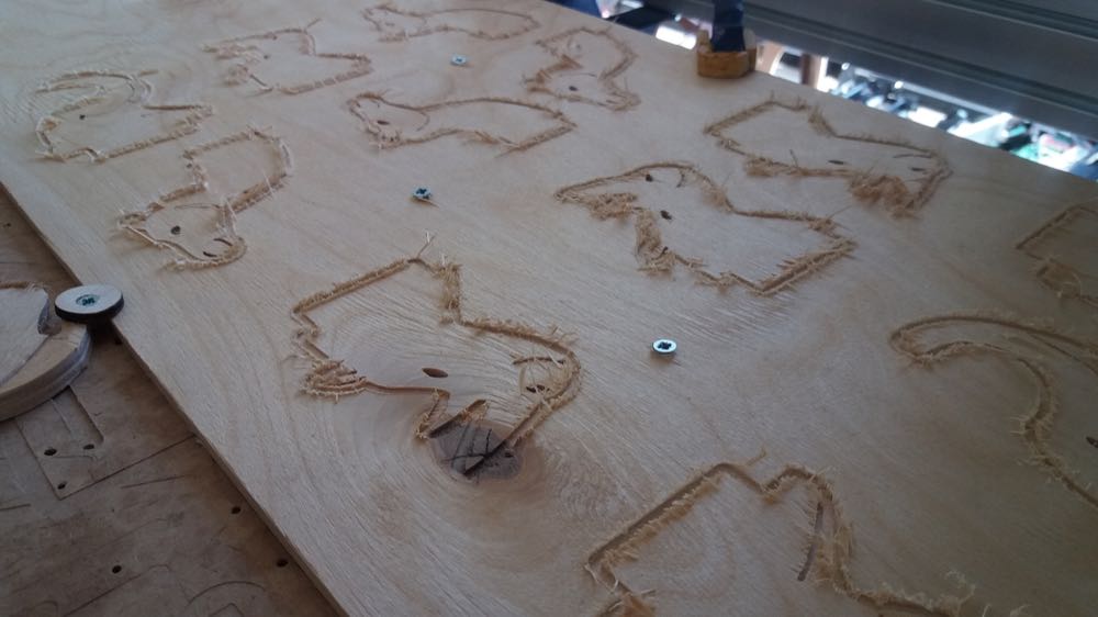
After my jobs were saved, I started cutting. First, I cut the pockets for the numbers and letters.
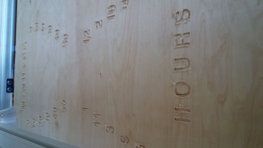
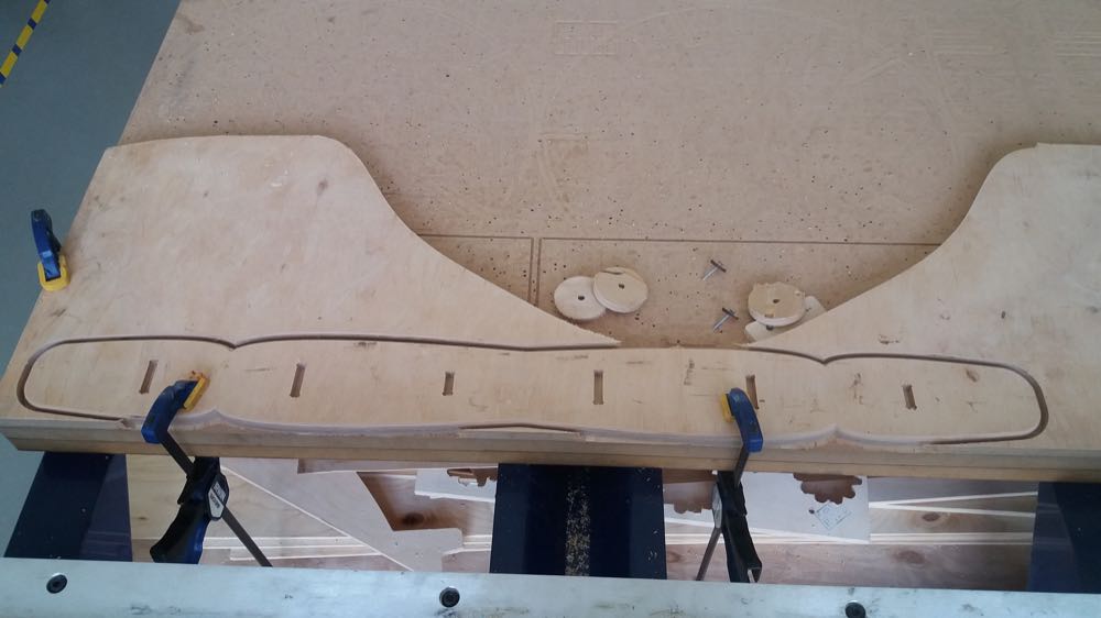
Afterwards, I cut the profiles:
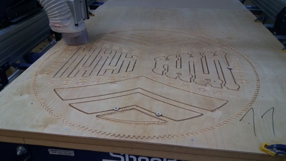
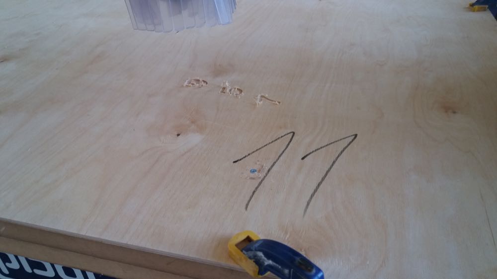
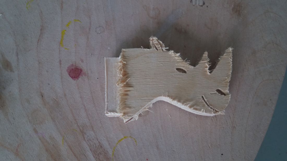
Unfortunately, I made a terrible mistake. I mixed up outside and inside of the line when making some of my profiles and this makes my whole work worthless, since some critical details are too small or too large:
Since it was already the end of the week, I didn’t have time to do anything else.
Alternative project
Since my former project was broken, I decided to undertake something a bit simpler when I came back to it at the end of Fabacademy. I wanted to make a cloth hanger.
Design
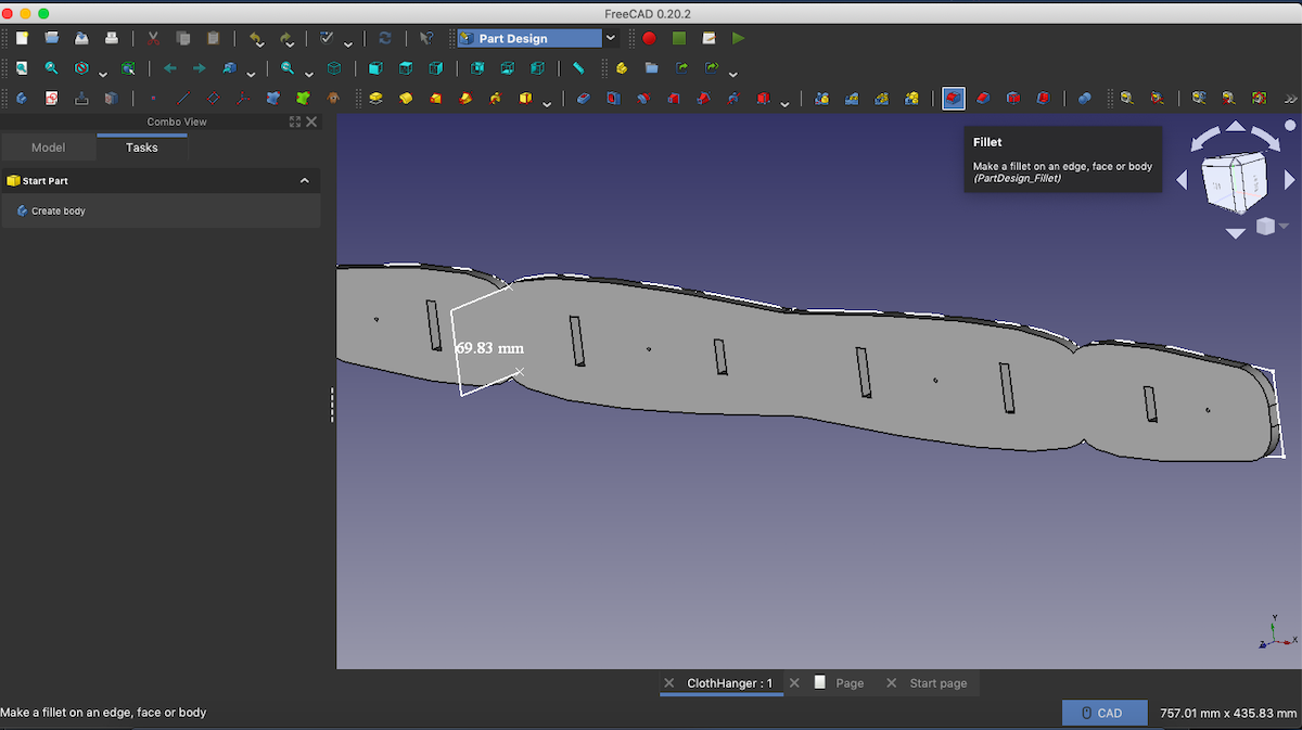
I designed the main part that would be hanged on the wall using Freecad.
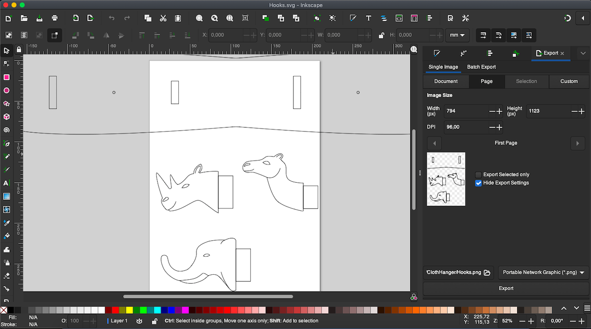
The hooks on which the cloths would hang were designed using Inkscape, since this level of details was easier to achieve with a 2D design software:
Cutting
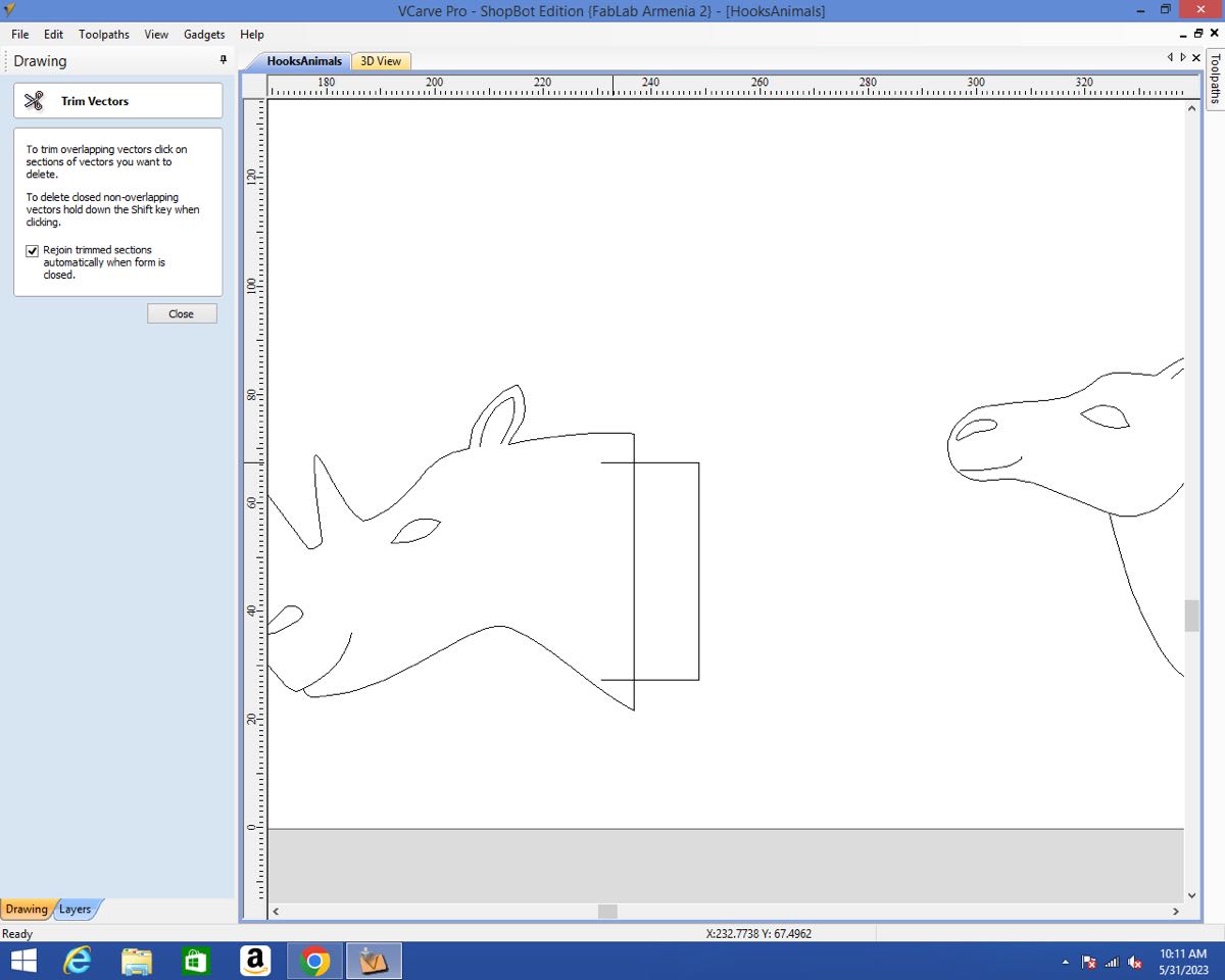
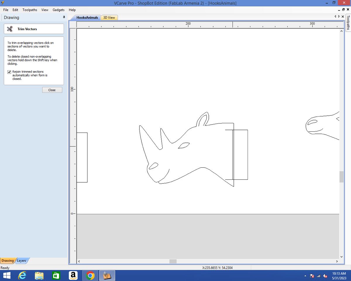
Once my designs were ready, I moved to VCarve Pro on the computer that would control the Shopbot. I wanted to pocket a rectangle on the part of the hook that would serve as a joint as well as cut out the profile of the whole hook.
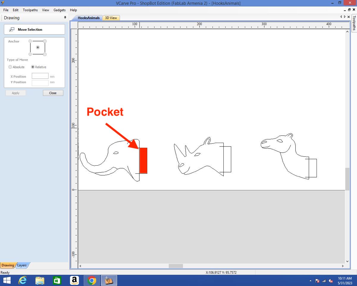
It wasn’t that straight forward, since I needed two different closed vectors that would overlap.
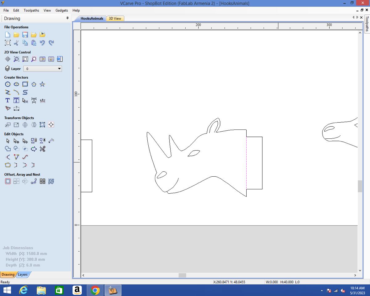
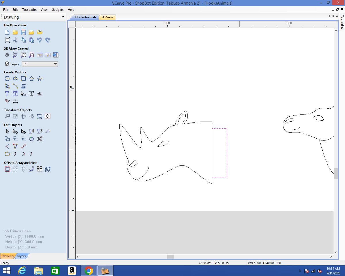
By slightly shifting the drawing using the arrows, trimming the vector and then shifting it back in place, I was able to obtain the desired vectors:
Once the vectors were as I wanted, I just had to copy paste them and finally join them:
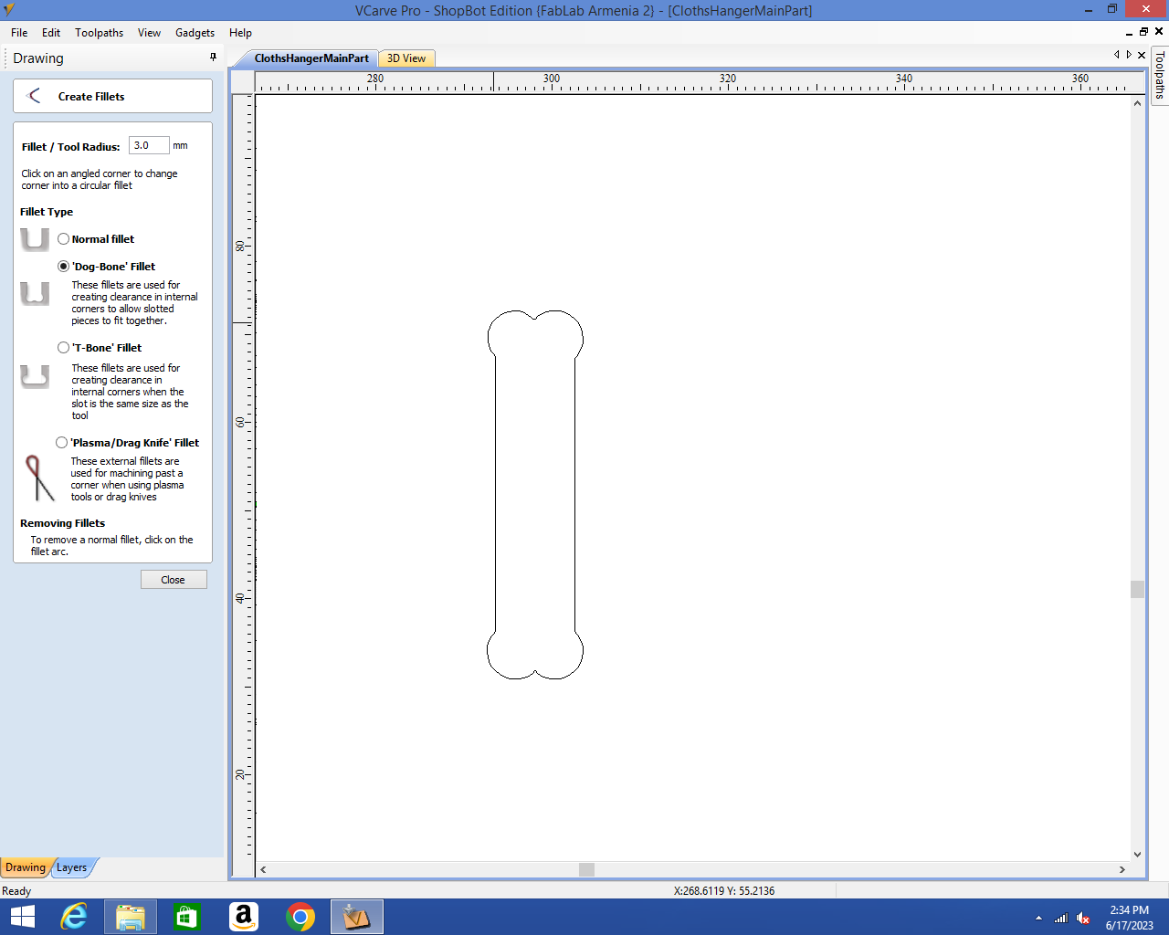
Once the hooks were ready, I prepared the main part. The main preparation was to add dogbones in the pockets. I used the Create Fillet tool:
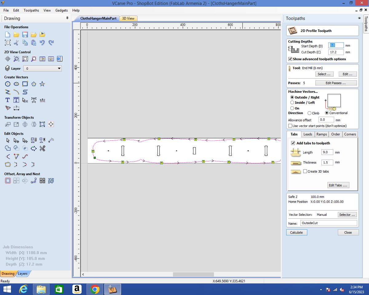
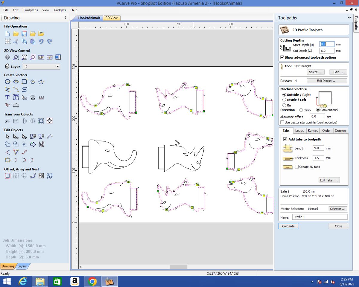
I could then create the toolpaths. First I created the Profile for the main part. I learnt from my mistake and was always careful to check on which side of the line the tool would cut. I used the 6mm upcut endmill and added the tabs.
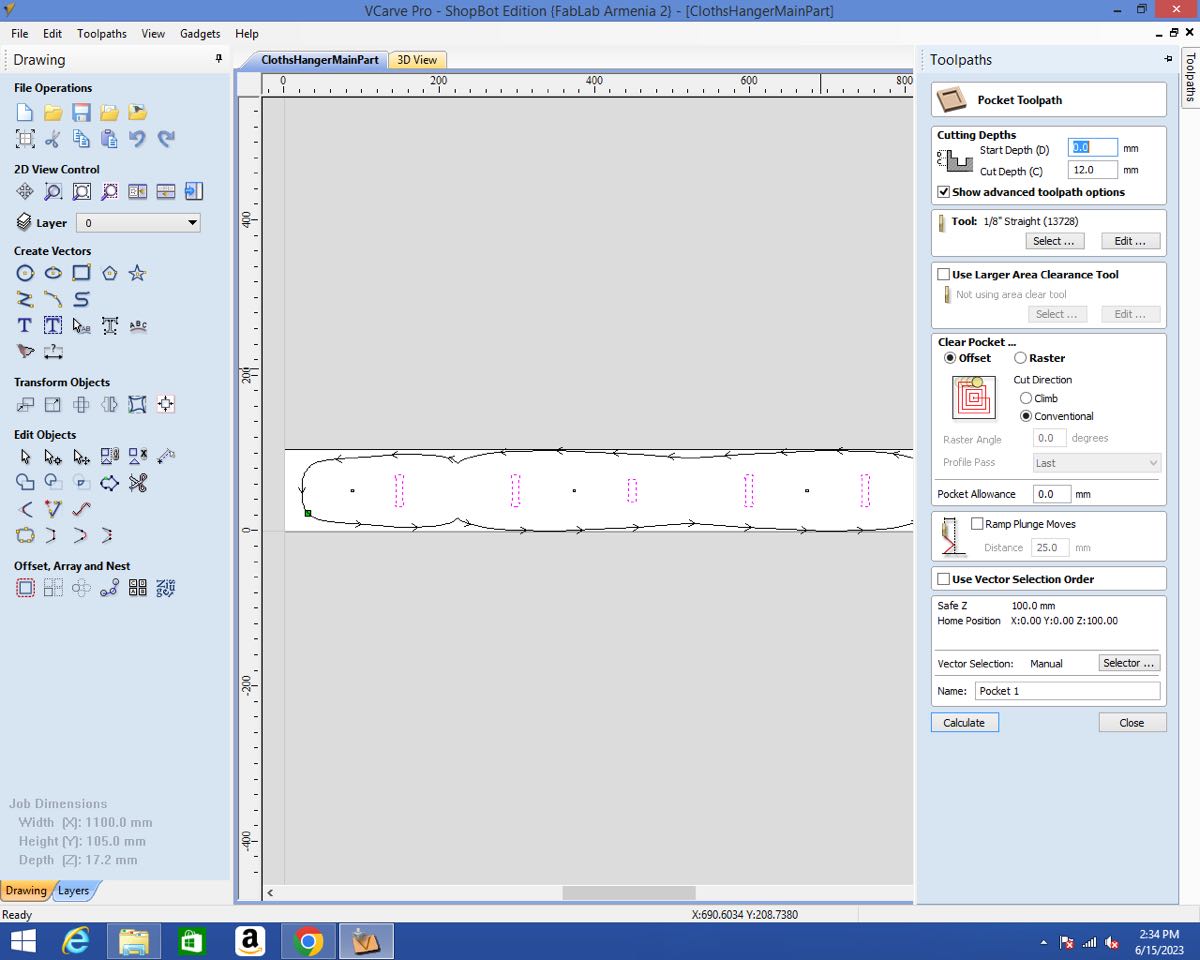
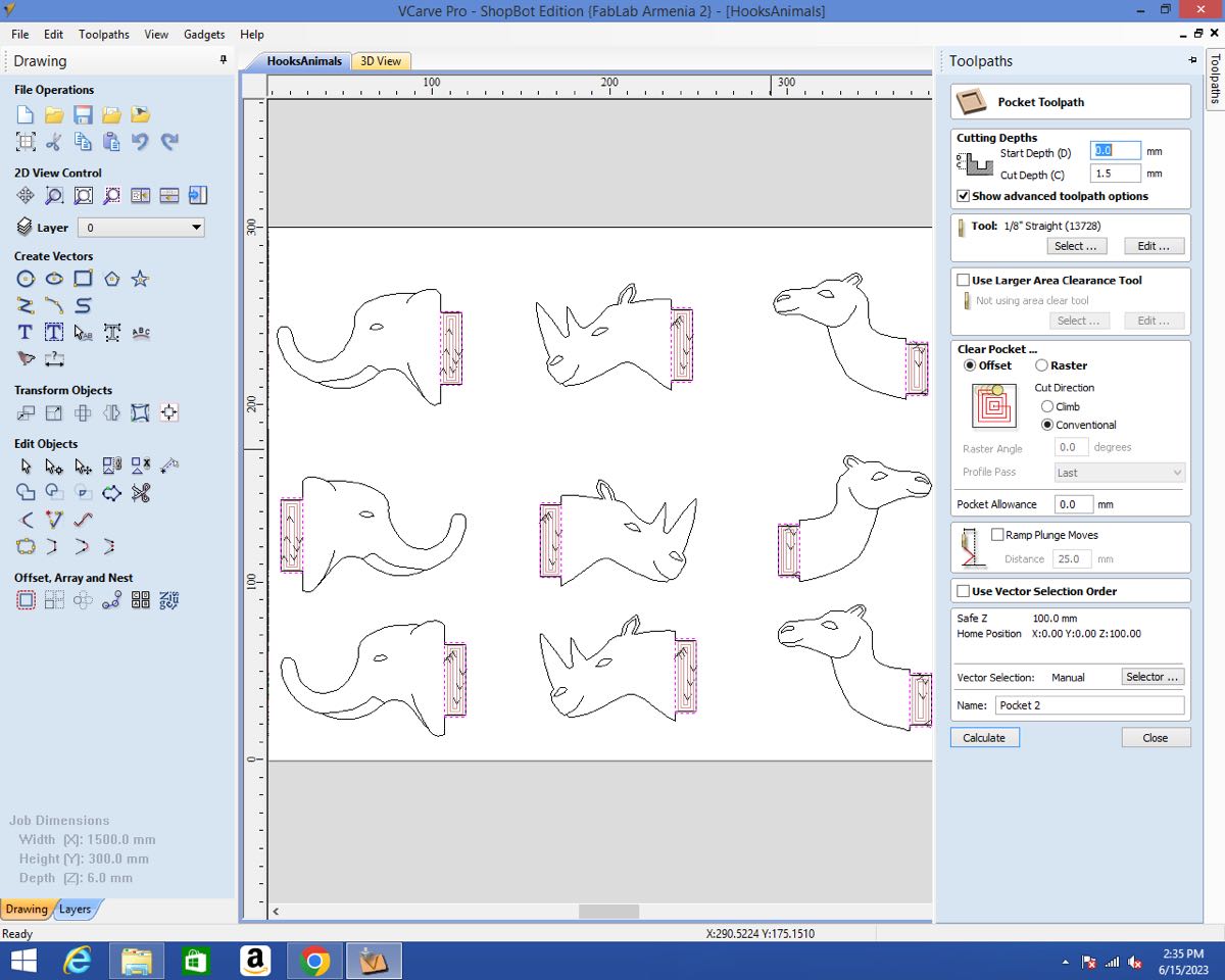
For the pockets for the joints, I used a 1/8 inch endmill.
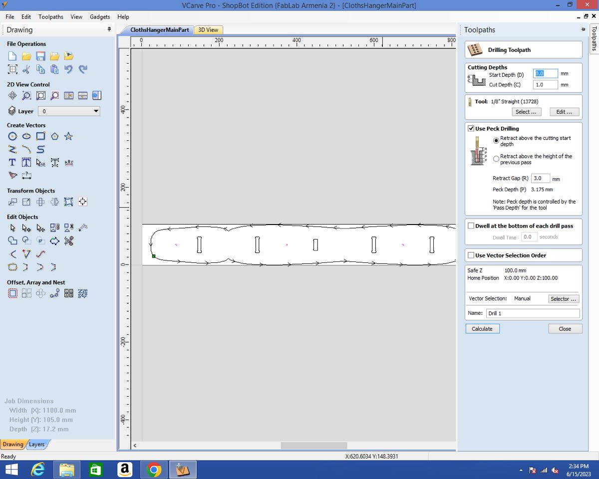
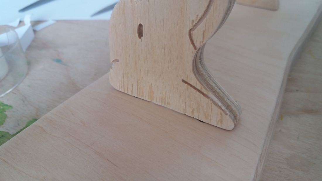
I also drill some holes with a very small depth in order to mark the places for the screws later. But since I didn’t know yet which screws I would use, I didn’t want to drill through.
I wanted to add some kind of chamfer, so I used a 90° Vbit. This time, I cut on the line.
For the hooks, I created the following toolpaths:
The profiles with the 1/8 inch endmill.
The pockets with the same endmill.
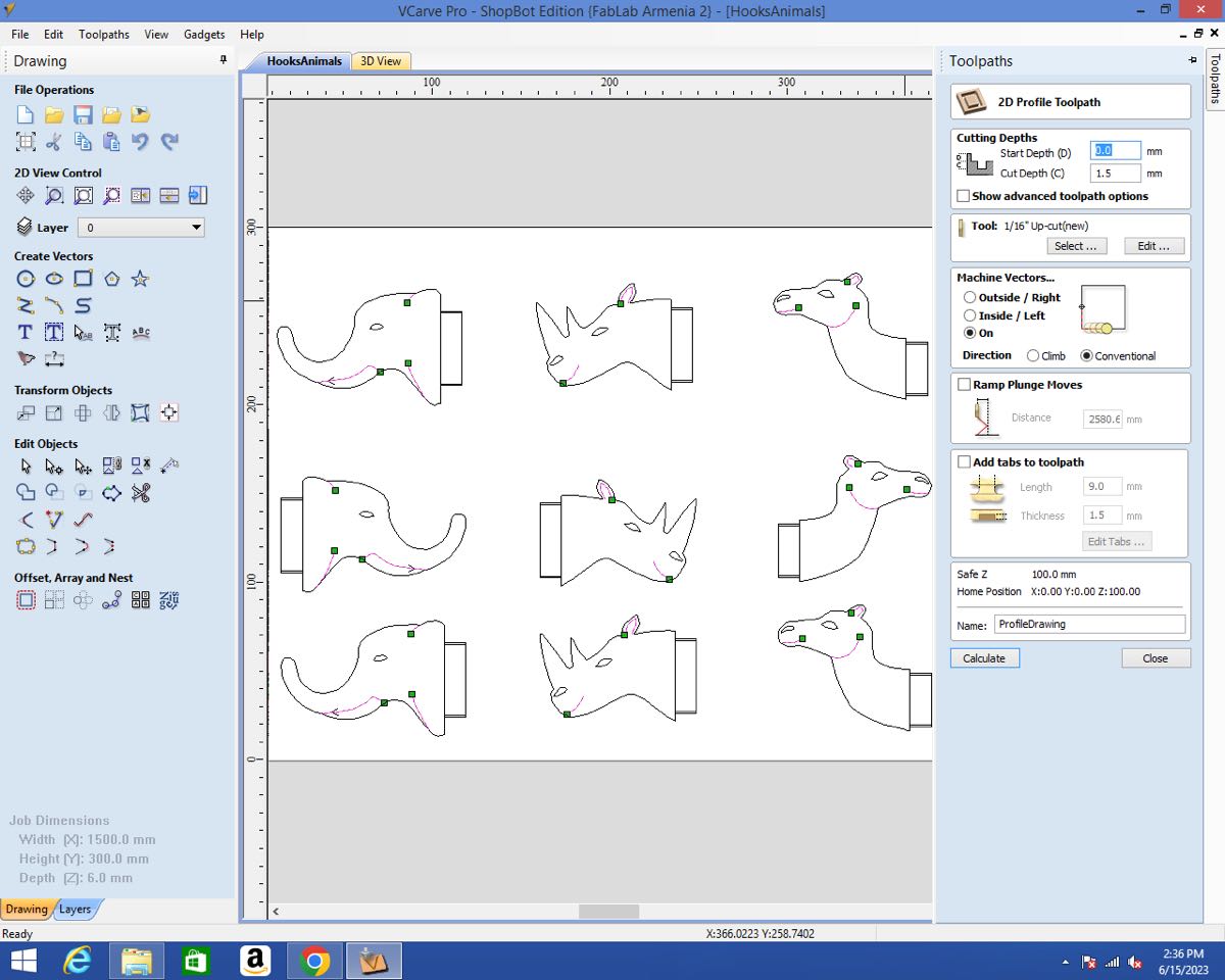
For the smaller pockets, I used the 1/16 inch upcut endmill.

Eventually, I carved the small lines with the 1/16 endmill at 1.5 mm depth using the Profile toolpath On the line.
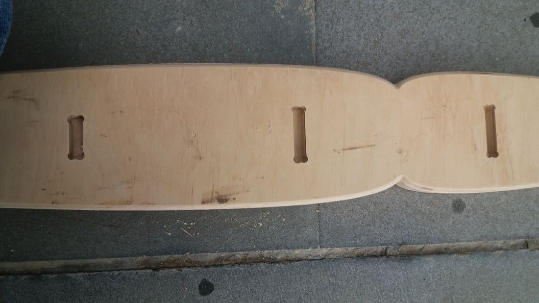
I could then cut the main part. The tricky part was to secure the wooden board to the MDF sacrificial bed. Since I didn’t have much margin, many of the tabs wouldn’t hold to anything and if I would just cut as usual, the part would probably move at the end. In order to prevent this, I paused the job just after starting the last pass and added a clamp. Few tens of cm later, I did the same:
Once the main part was cut, I started by securing the wood plank for the hooks.
I could then launch all the jobs one after the other:
However, I noticed while it was pocketing that the plank wasn’t flat enough. I had to add some screws to prevent it from lifting:
Post processing and Assembling
The first step of post processing my parts was to remove the tabs. For this, I used a file and some sandpaper.
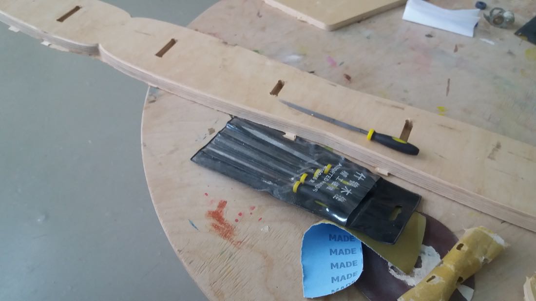
Afterwards, I wanted to sand the whole surface of the main part in order to remove the dark spots.
For this task, I used an electric sanding machine.
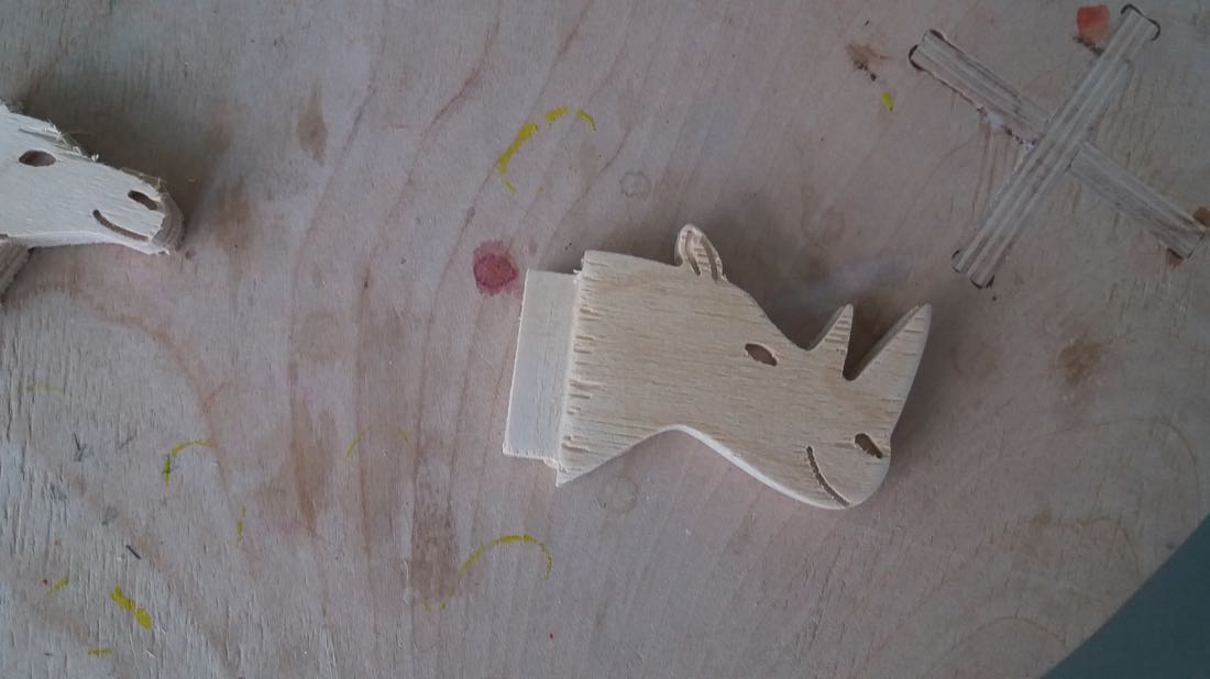
Once the main part was clean, I post processed my hooks. The upcut endmill did a pretty rough job:
But I was able to clean most of it with the help of sandpaper.
Since my plank of wood wasn’t totally flat when I was pocketting the surfaces for the joints, they were not thick enough. This made the hook pretty shaky:
To fix this issue, I folded some piece of paper and stick it inside the joints using some scotch tape:
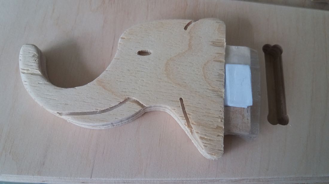
It worked well and the hooks are now much more steady.
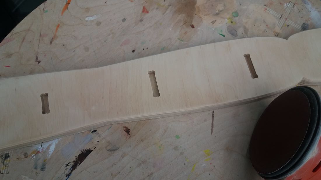
The basic idea for making the part of the hook that would be inside the joint thinner was to try to hide the dogbones. It worked not too bad, since theses are barely visible:
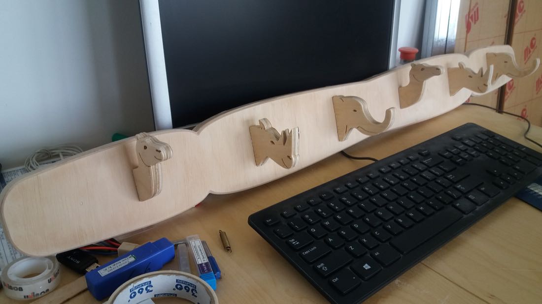
And here is the final result (not yet hanged on a wall, since I don’t know yet where I want to put it):
Conclusion
This week was so far the hardest one for me. Not because it was technically more difficult, but because I managed the time very badly. At the beginning of the week I really wanted to try making something a bit innovative, and as the week was passing by and I wasn’t making too much progress, I didn’t have the courage to back down from my project for something more simple. At the end of the week, I even failed when cutting the design I spent one entire week to make. This was quite hard on me, so I abandoned this project.
However, despite the difficulties, I learnt quite a lot. The mistakes I made along the way taught me some valuable lessons and I hope I won’t make them anymore in the future.