Week 9: Output Devices
✓ add an output device to a microcontroller board you’ve designed
✓ and program it to do something
Group assignment
For this group assignment, we had to measure the power consumption of some output devices. We measured an LED strip, a fan and a DC motor.
- It is possible to measure the current and the voltage using the power supply or a multimeter.
- Usually, we use the black wire for the ground and the red cable for the phase.
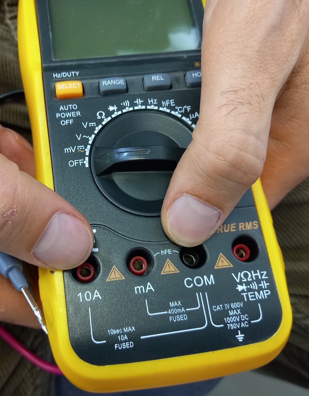
- When using a multimeter, don’t forget to change the plugging of the red wire when switching from voltage/resistance to current.
- When measuring current with a multimeter, we need to know approximately the value of the measured current in order to plug the red wire either in the 10A or mA hole. If we draw too much current, the fuse would break and would need to be replaced.
- To measure the maximum current a DC motor can draw, we can hold the spinning the shaft.
Once we measured the current (I) and voltage (U) with the multimeter, we can calculate the power (P) with the following formula:
P = U * I
Stepper motors
For this week, I wanted to try to control a stepper motor. Specifically, I used a motor we had in the lab: the Nema 17 stepper motor. It is a 2-phase stepper motor with 1.8° per step.
To understand the inner working of these motors, I watched this video.
Contrary to a DC motor, which would work as soon as some appropriate DC current is applied to it, a stepper motor needs to be driven by a microcontroller. The big advantage of a stepper motor is that it can be driven in small steps and kept at a specific position.
There are few types of steppers, but they all have coils on the stator arranged into phases (2 phases in the case of the Nema 17) and permanent or non-permanent poles on the rotor. The working of a stepper motor is illustrated below:
The main control methods are the followings:
- full step: provides the most torque, but the lowest resolution.
- half step: provides less torque and more resolution.
- micro stepping: provides the least torque but the most resolution.
Designing the board
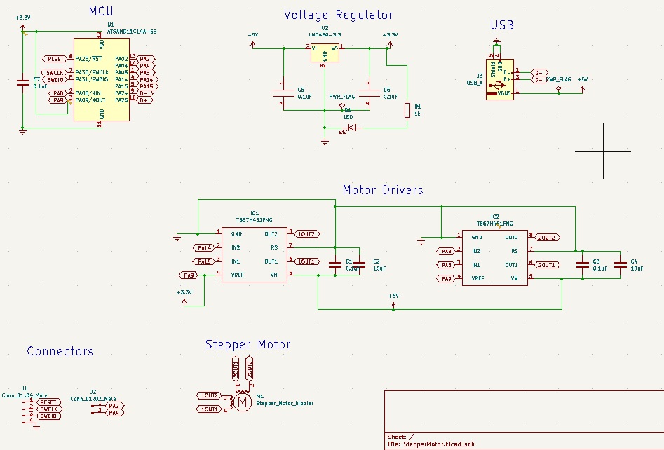
As a starting point, I took the board available on the lecture page:
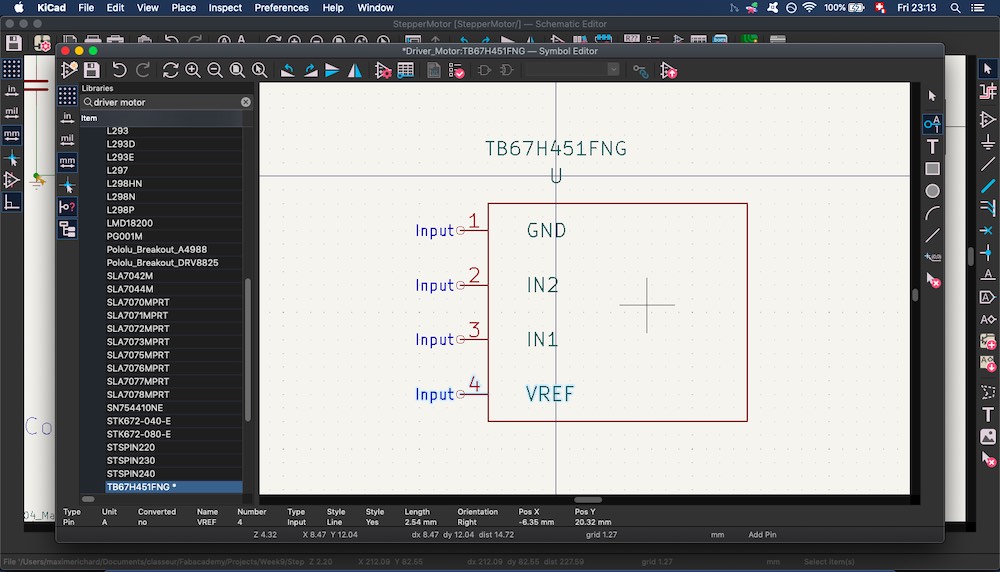
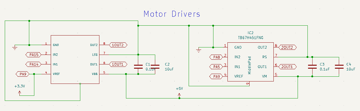
I made few modifications, like adding an LED that would light up whenever the board is connected to the USB. Indeed, I had troubles with my former board, since my USb connection wasn’t very stable and I had no way of knowing wether it was correctly plugged. This board had a component that I didn’t find in the library installed in my Kicad. I had to use the Tools -> Symbol Editor to create a new Symbol for the TB67H451:
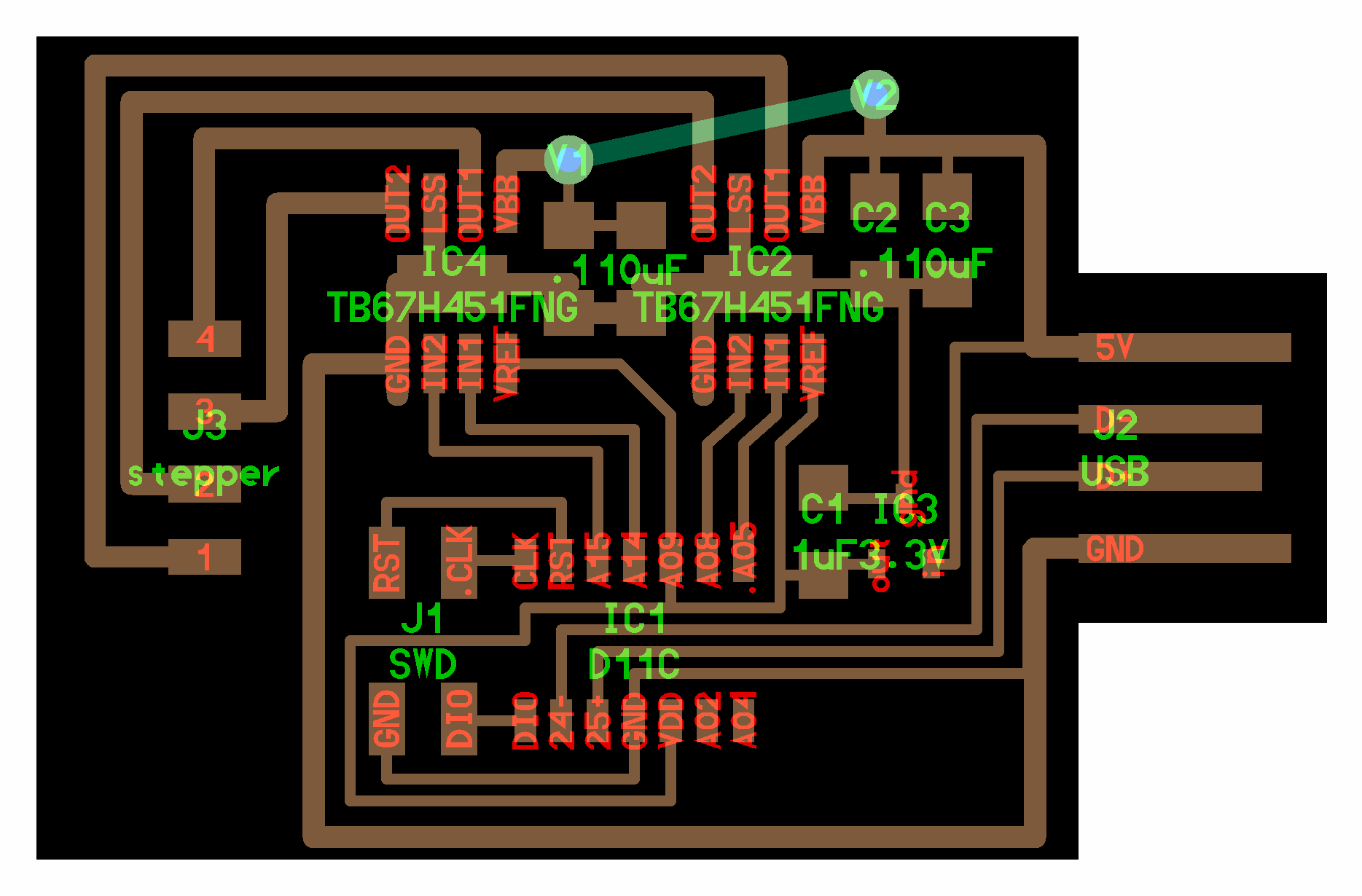
I had the following schematic for my boad:
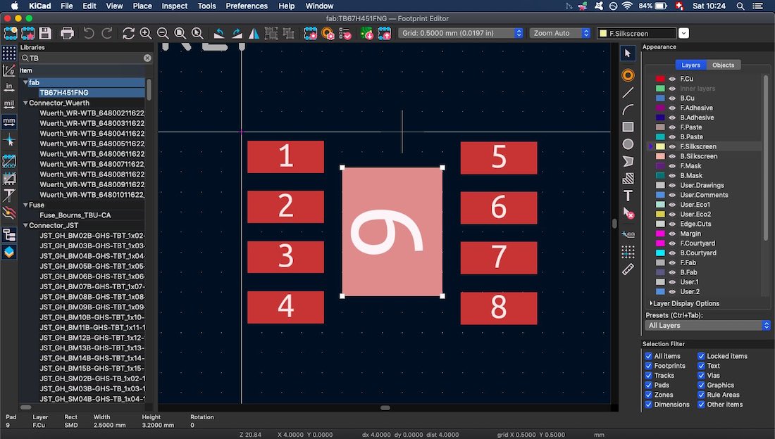
When it came to design the PCB, I also needed to use the Tools -> Footprint Editor:
Later, my instructor, Babken, told me that there was a corresponding symbol in the Fab library: A4953-H-BRIDGE-MOTOR-DRIVER. So I replaced one of my drivers by this one, to see if I my footprint was good enough:
I had to edit the pad clearance on my custom footprints:
![]()
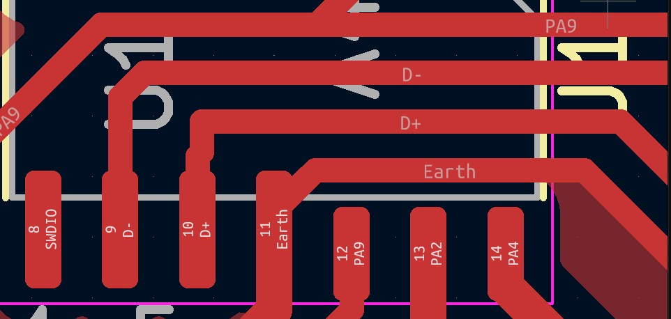
The footprint of my SAMD11C14 wasn’t the same as the one used in the model board designed by Neil. In order to fit the wires under the MCU, I had to shrink the size of some of its pads:
Milling the board
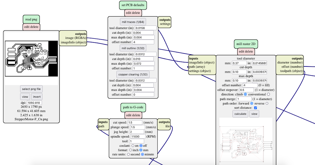
To create the g-code from the png file, I used mods. I had an issue with some of the traces that had a gap of 4mm but were not cut with a tool diameter of 1/64 inch. So I set the diameter to 0.37mm, which fixed this problem:
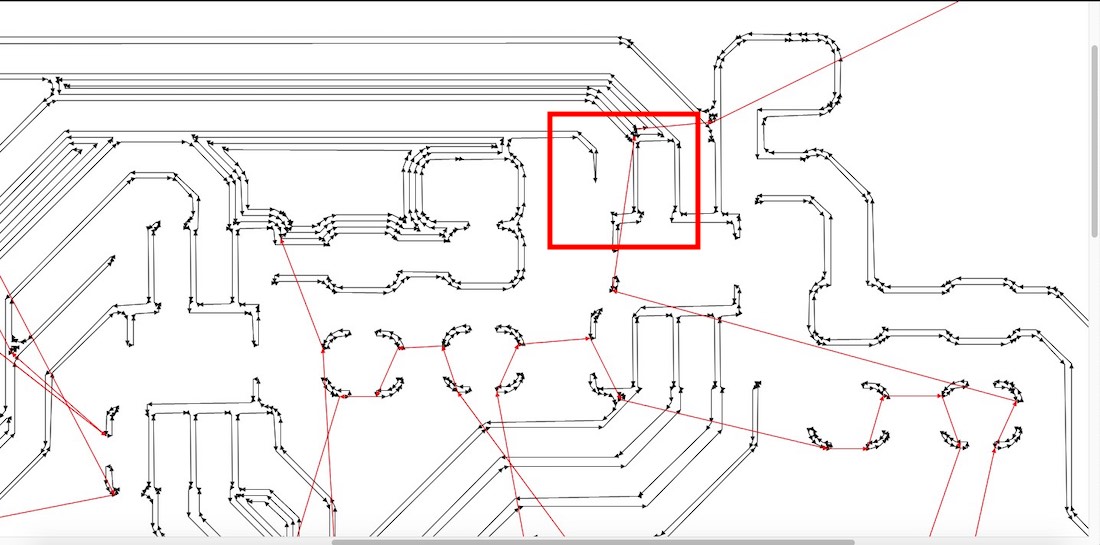
I still had some parts which were not carved because I changed the clearance of some of the pads:
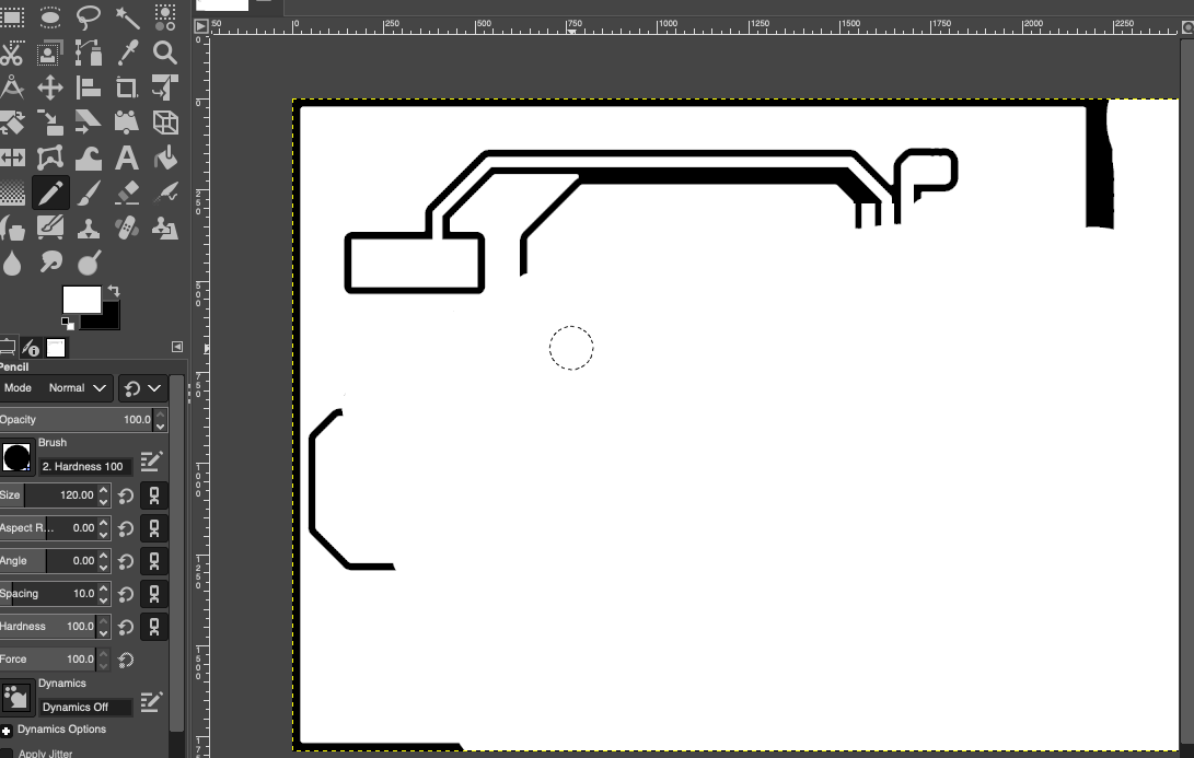
To fix this, I used the pencil tool in GIMP:
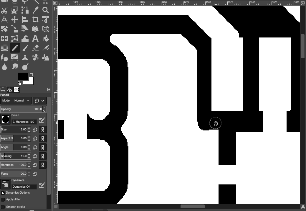
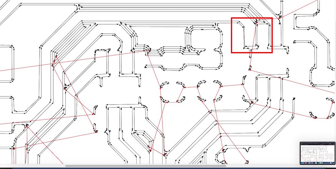
And was able to fix the pads:
As last week, I had issues with the uneven character of our CNC table. Some part of my board wasn’t milled properly the first time:
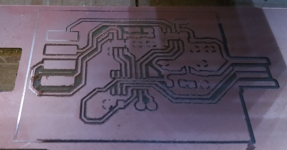
I had to fix it in GIMP:
Soldering and Programming
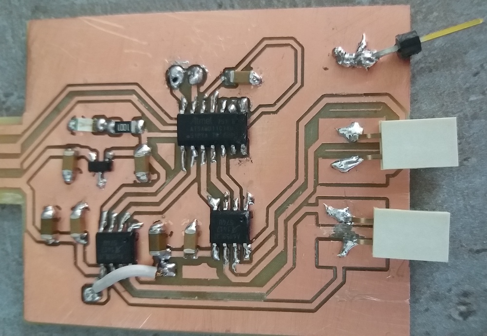
Once it was carved, I could solder the components:
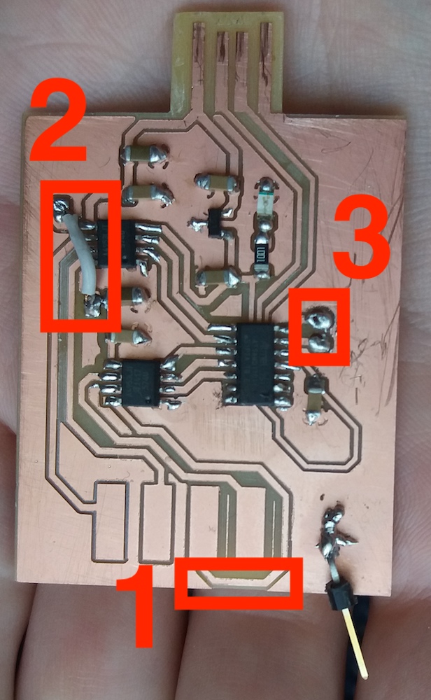
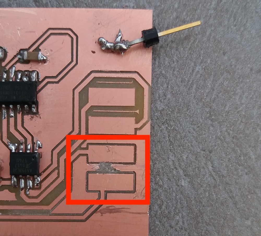
I had few challenges: the cutout was shifted compared to the carving (1) because of the editing and reexporting I did in Inkscape and GIMP. This caused one track to be too close to the edge and, more importantly, the USB port wasn’t centered. I was afraid I would have some USB connection issues but, fotunately, this did not happen.
Then, I had to cut and solder two parts of the PCB (2).
Finally, I had trouble soldering the THT pinheaders (3). I didn’t really know what I was doing when I designed my PCP and I drew the holes by hand. They were apparently much too large and I wasn’t able to solder the pins despite the large quantity of solder I used.
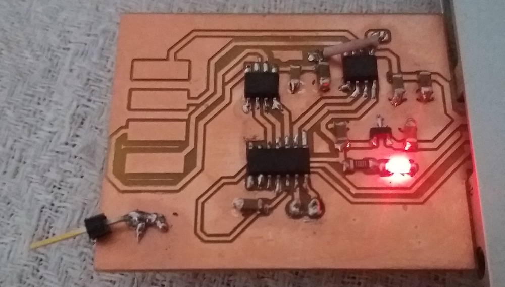
After soldering my components, I connected the board to my laptop and it was very satisfactory to see the LED light up:
I wanted to try using some kind of programming clamp that should come on top of the MCU and make the contact with the programming pins:
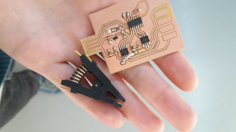
Unfortunately, I was unable to get any contact between the metal of the clamp and my pins despite many trials. Since I hadn’t added any pinheader for the programming pins, I was a bit despaired. I resolved to try making the contacts by holding the wires directly against the pins. I just added a pinheader for the ground and tried this solution: it worked!
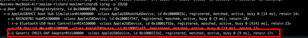
However, when I checked my board on my laptot using ioreg -p IOUSB, I noticed
something strange: I had flashed the wrong bootloader! My board was now a programmer.
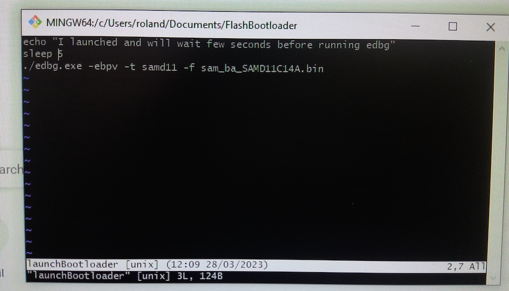
I had to start this tedious programming all over…
To make this task a bit easier, I wrote a very short bash script to wait few seconds before launching the edbg command, so that I could hold the wires in place without having to press the Enter key at the same time:
I also had to specify the programming board ID using the “-s” option, because I had now two programming boards.
Installing the motor
I made a mistake when I adapted the board design and my pads were much too large to fit 4 pin headers together. I could however fit a double pin header for two pads. In order to prevent a short between a pad and the Earth, I scratched the copper between the pads:
Then I could solder the pin headers:
I followed this tutorial on stepper motors which, because I didn’t know the model of my motor, recommended to check the wiring using this method:
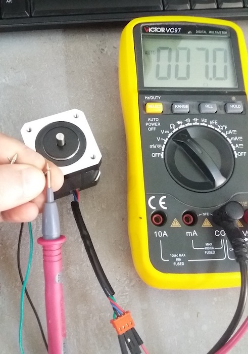
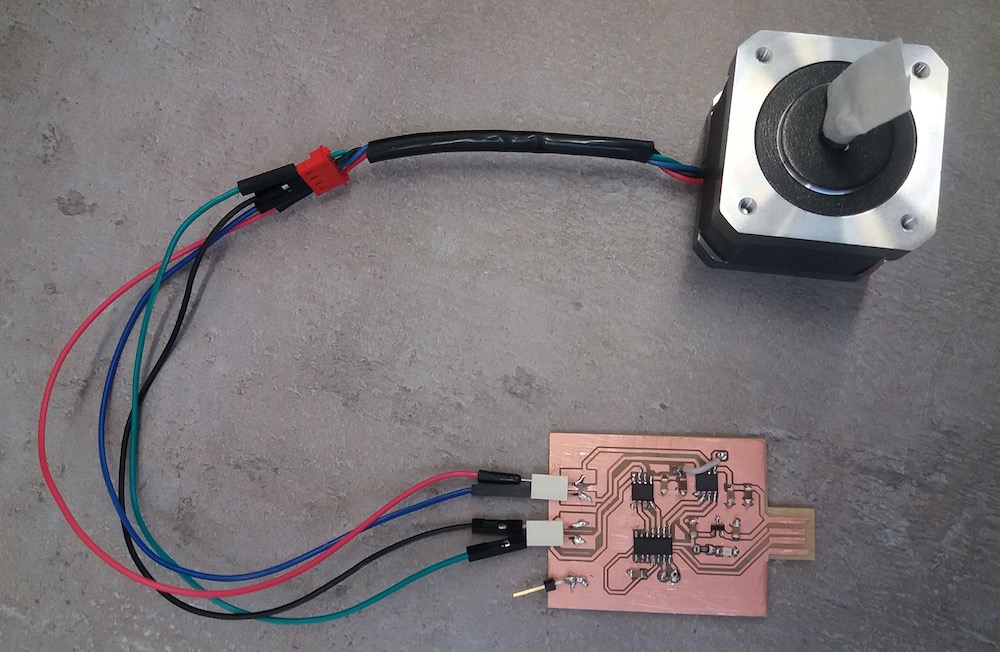
After finding out what were the wire pairs, I could connect my motor to my board:
Programming the motor
As a starting point, I used Neil’s code:
//
// hello.stepper.bipolar.D11C.ino
//
// bipolar stepper D11C hello-world
//
// Neil Gershenfeld 11/12/22
//
// This work may be reproduced, modified, distributed,
// performed, and displayed for any purpose, but must
// acknowledge this project. Copyright is retained and
// must be preserved. The work is provided as is; no
// warranty is provided, and users accept all liability.
//
#define output(pin) (PORT->Group[0].DIRSET.reg = pin)
#define set(pin) (PORT_IOBUS->Group[0].OUTSET.reg = pin)
#define clear(pin) (PORT_IOBUS->Group[0].OUTCLR.reg = pin)
#define compare(value,pin) (value > pulse) ? set(pin) : clear(pin)
#define A2pin (PORT_PA15) // H-bridge output pins
#define A1pin (PORT_PA14) // "
#define B2pin (PORT_PA08) // "
#define B1pin (PORT_PA05) // "
#define on 40 // PWM on count; ~0.7 us/tick
#define off 10 // PWM off count
#define pulse_count (on+off) // PWM total count
#define PWM_count 50 // number of PWM cycles
#define step_count 100 // number of steps
//
// single step
//
void step(uint32_t A1value, uint32_t A2value, uint32_t B1value, uint32_t B2value) {
   for (uint32_t count = 0; count < PWM_count; ++count) {
      for (uint32_t pulse = 0; pulse < pulse_count; ++pulse) {
         compare(A1value,A1pin);
         compare(A2value,A2pin);
         compare(B1value,B1pin);
         compare(B2value,B2pin);
         }
      }
   }
//
// clockwise full stepping
//
void step_full_cw() {
   step(on,0,on,0);
   step(0,on,on,0);
   step(0,on,0,on);
   step(on,0,0,on);
   }
//
// clockwise half stepping
//
void step_half_cw() {
   step(on,0,0,0);
   step(on,0,on,0);
   step(0,0,on,0);
   step(0,on,on,0);
   step(0,on,0,0);
   step(0,on,0,on);
   step(0,0,0,on);
   step(on,0,0,on);
   }
//
// counter-clockwise full stepping
//
void step_full_ccw() {
   step(on,0,0,on);
   step(0,on,0,on);
   step(0,on,on,0);
   step(on,0,on,0);
   }
//
// counter-clockwise half stepping
//
void step_half_ccw() {
   step(on,0,0,0);
   step(on,0,0,on);
   step(0,0,0,on);
   step(0,on,0,on);
   step(0,on,0,0);
   step(0,on,on,0);
   step(0,0,on,0);
   step(on,0,on,0);
   }
void setup() {
   //
   // initialize H-bridge pins
   //
   clear(A1pin);
   output(A1pin);
   clear(A2pin);
   output(A2pin);
   clear(B1pin);
   output(B1pin);
   clear(B2pin);
   output(B2pin);
   }
void loop() {
   //
   // main loop
   //
   while (1) {
      //
      // full step
      //
      for (uint32_t i = 0; i < step_count; ++i)
         step_full_cw();
      for (uint32_t i = 0; i < step_count; ++i)
         step_full_ccw();
      //
      // half step
      //
      for (uint32_t i = 0; i < step_count; ++i)
         step_half_cw();
      for (uint32_t i = 0; i < step_count; ++i)
         step_half_ccw();
      }
   }
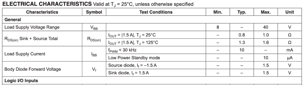
First, I tried to make the motor spin by just plugging the board to the USB port of my laptop. Nothing happened :-(. I guessed it was due to a lack of voltage, but I didn’t know exactly how to proceed correctly to increase the voltage. In the review with Jani and Babken, I explained my problem and they confirmed my intuition and told me that I could just use the clamps of the power supply and plug them to the Ground and +5V of the USB port of my board. I used the same power supply that we used for our group assignment. Jani also checked the datasheet of the A4953 driver and saw that the minimum voltage was 8V:
So I tried with this voltage and:
I also tried to change the code a bit. I wanted to read one of the free pins and check when this input was changing (when I would bridge this pin with the Ground with my finger) to make a step with the motor. I checked this documentation to understand the mapping of the SAMD11C14 pins to the Arduino pins:
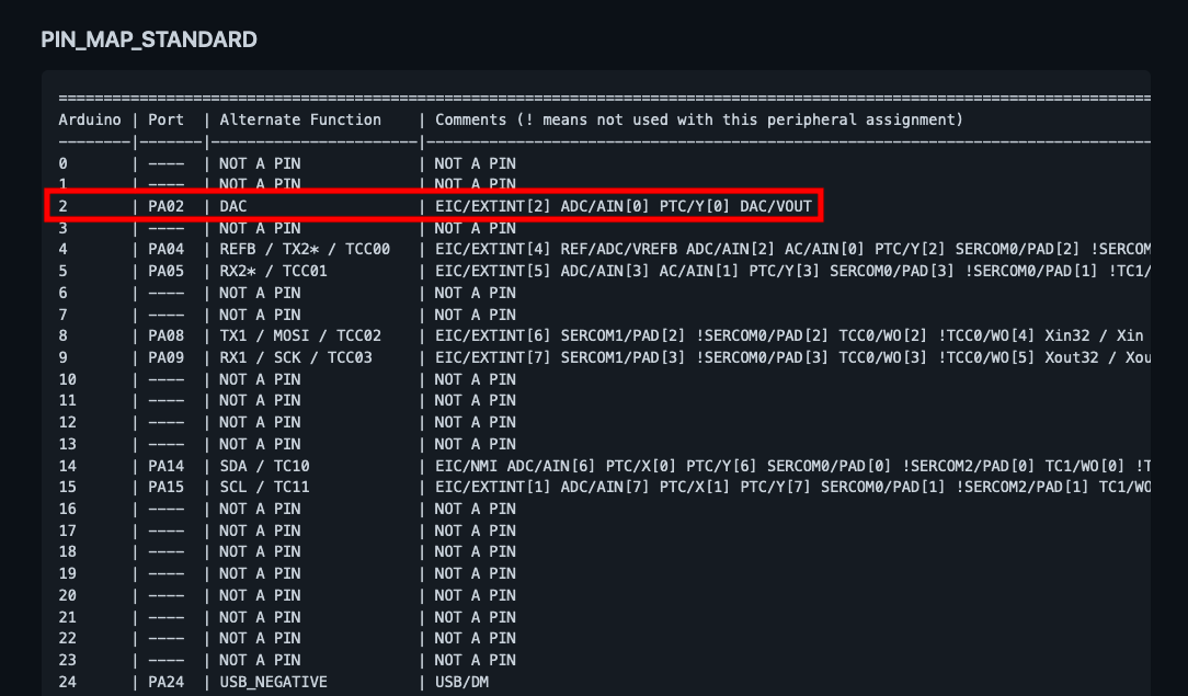
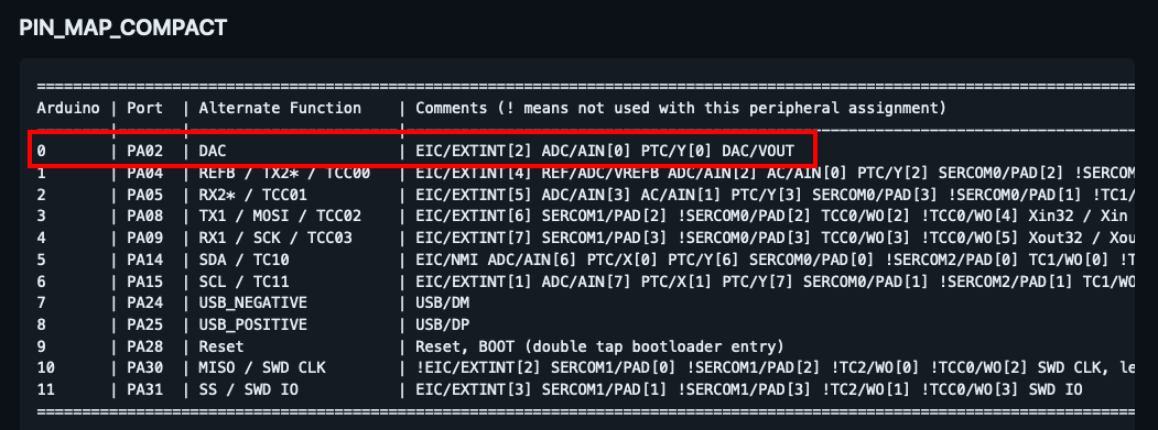
I noticed that the compact table from this documentation didn’t give the same pin number as the one above:
Once my modifications were done, the compiler complained that my sketch was too large:
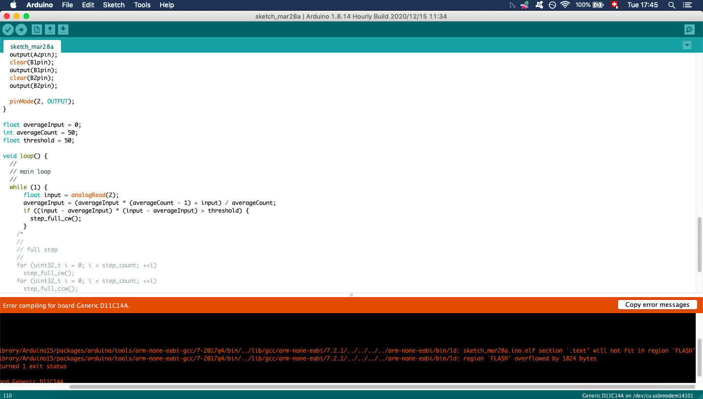
I used again the search bar of Fabacademy to see if anyone else had had the same problem. A few people encountered the same issue. Nadieh Bremer had some great tips on how to deal with this problem. I shrinked the size of my variables by switching from “int” to “uint8_t” and “uint16_t”. I also read the reference for the analogRead() function and realised that it was actually returning an int and not a float. Indeed, this function is returning an integer between 0 and 1023 which maps the voltage between 0 and the operating voltage. The resolution of this number is therefore a few mV. After these few fixes, I managed to compile my sketch. Here is the modified part of the code:
...

void setup() {
  clear(A1pin);
  output(A1pin);
  clear(A2pin);
  output(A2pin);
  clear(B1pin);
  output(B1pin);
  clear(B2pin);
  output(B2pin);

  Serial.begin(9600);
  pinMode(2, OUTPUT);
}

uint16_t averageInput = 0;
uint8_t averageCount = 50;

void loop() {
  while (1) {
      uint16_t input = analogRead(2);     //read the pin 2
      averageInput = (averageInput * (averageCount - 1) + input) / averageCount;    //compute an average of the last 50 input reads
      Serial.println(averageInput);
      if (averageInput < 200) {     //if the average input is below 200, make a full step clockwise
        step_full_cw();
        Serial.println("Touch down!");
      }
  }
}
And here is the result:
Other output devices that I used later
After this week I explored other types of output devices:
Conclusion
Since I didn’t manage to program my board during the last week, I started this week by addressing this problem. When designing and programming this week’s board, I also encountered many issues. It felt like I had or made an error at each step of the way, which was a bit frustrating. Maybe I am not careful enough when making some of the critical steps. On the other hand, by overcoming all these problems, I learnt how to solve many different kind of common issues and it made me feel more confident. I also learnt that it is often more efficient to use the Fabacademy search bar than google when searching solutions for Fabacademy related issues.
Files of the week
PNG and SVG files for carving and cutting the board