Week 6: Electronics Design
✓ design a development board to interact and communicate with an embedded microcontroller
✓ use the test equipment in your lab to observe the operation of a microcontroller circuit board
Group Assignment
Our group assignemnt can be found following this link -> link.
It was interesting to generate some code with chatGPT. I was first skeptical that the code would be usable, but was surprised when it produced the desired result. However, it was funny to see that it generated some useless code by multiplying by 1000 before dividing by 33000:
*1000 / 33000;
It was also surprising that the frequency detected for our ramp function was 2Hz, since it was repeated every second:
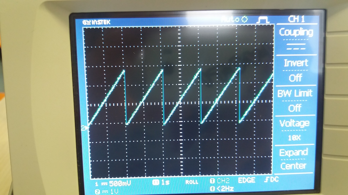
After some searching, I realised that even when there is no signal fed to the device, the displayed frequency is 2Hz:
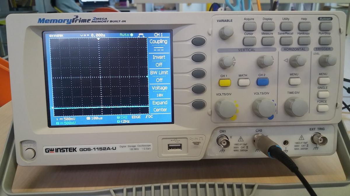
The device probably didn’t manage to properly detect the signal frequency and is just displaying a default value.
Since we didn’t have yet the recitation on debugging, it was hard for me to imagine use cases for how to use the oscilloscope. I checked the slides from last year and this website of a constructor to understand two use cases:
- Find a signal anomaly: for example if the voltage is not stable through time.
- Detect a noise: for example when there is no decoupling capacitor.
Capacitor on MCU: stabilize current resistance of a capacitor R = 1/f
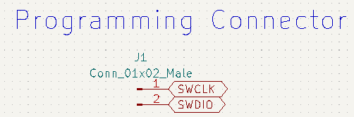
swclk and swdio for programming the board (in factory or without bootloader)
A bit of theory
Since electronics is rather technical, we started by learning a bit of theory. Probably the most important equation to know in this context is Ohm’s law:
U = R I
Where U is the voltage, R the resistance and I the current.
Onik asked us to research some information about voltage dividers. I searched on Wikipedia and found that, as the name suggest, it’s an electronics circuit used to obtain as output a signal with a voltage corresponding to a fraction of the input voltage. For simple usage, like in the case of direct current, a voltage divider can be made of two resistors in series. With Vin = I (R1 + R2) as a start, I did the quick derivation to obtain the output voltage:
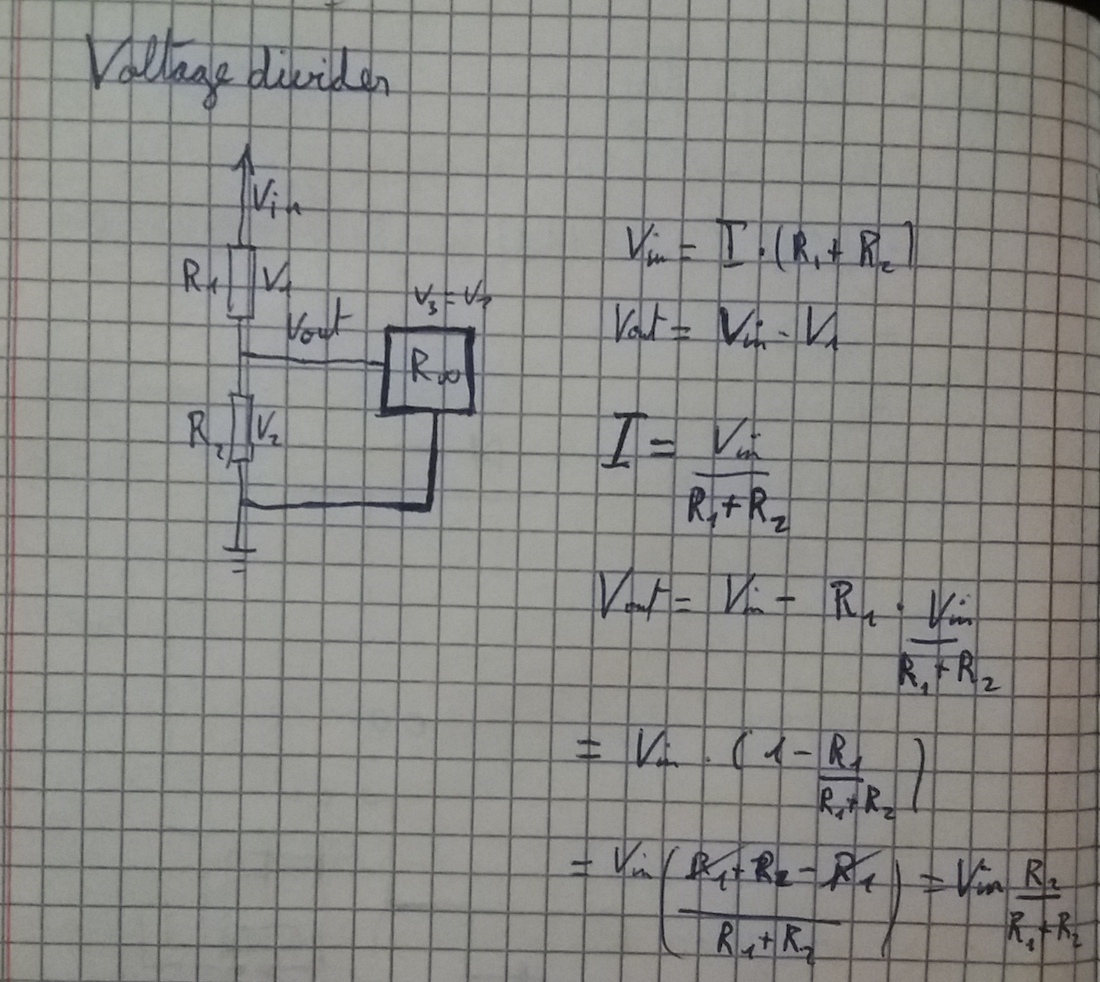
Voltage dividers are used in measurement devices such multimeters and also probably in oscilloscopes. It can also be used in voltage regulators. For example, if an MCU requires 3.3V but the device is plugged to a 5V USB port, the voltage regulator will divide the 5V input voltage in order to obtain 3.3V as output.
Development board design
Installing Kicad and libraries
I decided to go with Kicad since it was presented more extensively in the lecture. I couldn’t install the latest version of the software since it required MacOS version 11.0 or later. My version is 10.14.4 :-( Fortunately, the older versions of Kicad are readily available and I could download a compatible version from 2020.
I also had issues installing the Fabacademy libraries. The symbols libraries was incompatible with the installed version of Kicad and I also had to download an older version in order to solve this.
Designing the schematic
Onik gave us some advices on how to start and what to add on our board:
- a microcontroller (ATSAMD11)
- a USB power supply
- a Voltage regulator
- an LED
- a reset button
- connectors for the microcontroller pins
Kicad is actually a suite of several softwares each dedicated to a specific task in the workflow of PCB design. The first I used was Eeschema, which allows to draw the schematic of the board. The main tools I used during this tasks were the followings:
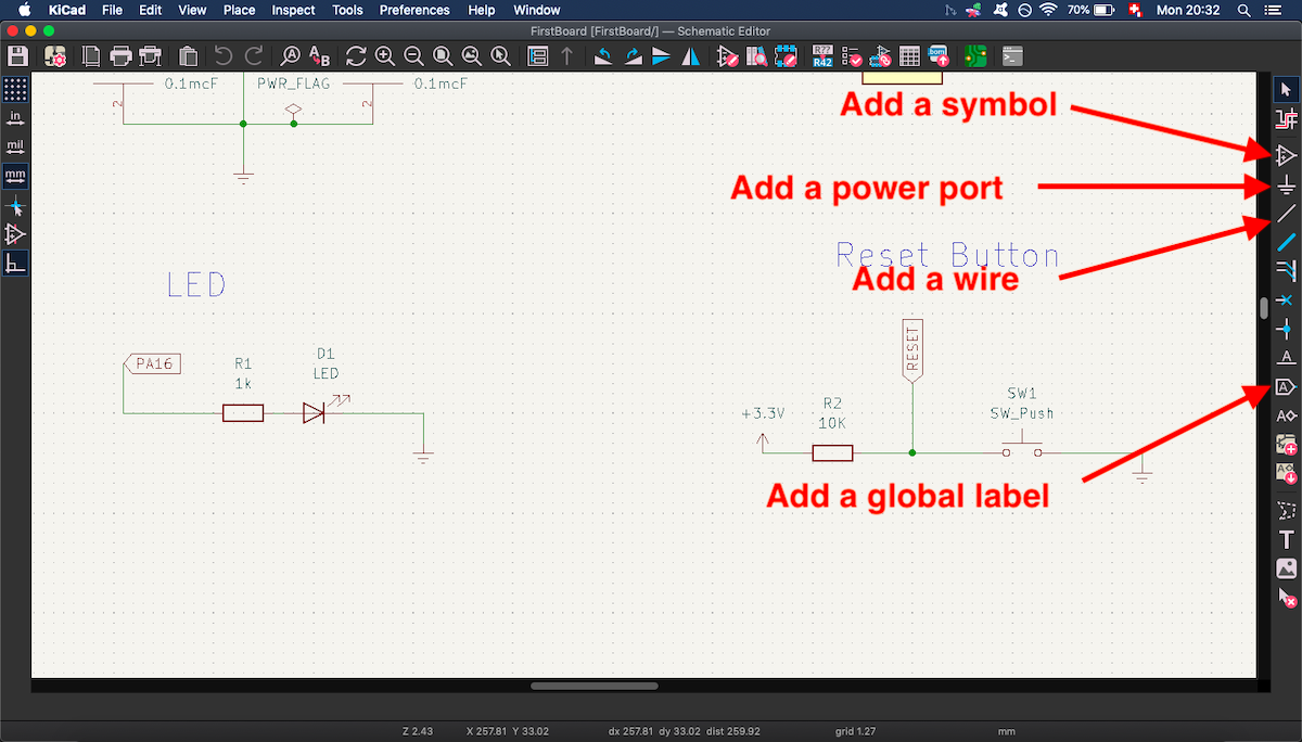
Besides the great explanations by Onik, I also watched this tutorial by Krisjanis Rijnieks from Aalto Fablab. I started by sketching for the microcontroller:
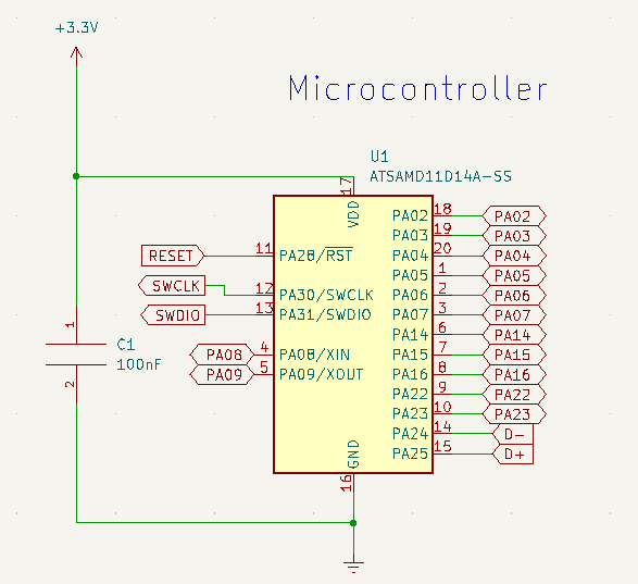
Onik talled us to add a capacitor parallel to the MCU. Its role is to stabilize the voltage and is called a decoupling capacitor. It should be placed between the VDD pin and GND pin. This link shows how it is able to remove some noise: above without decoupling capacitor, below with.
I then sketched the USB port:
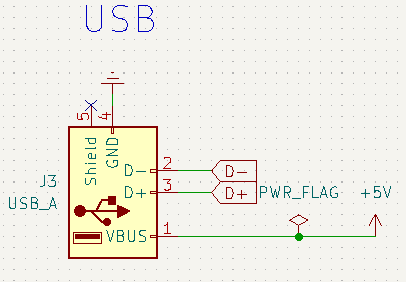
The D- and D+ pins are related to the USB communication protocol. Contrary to the I2C protocol, we don’t need a signal to give us the tempo, since the clock rate is known in advance and steady. The D- and D+ are digital pins that transmit 1s and 0s. To read one bit, we need both signals, since one is going up in voltage to give a 1 and the other one is going down in voltage to give a 1. The bit is then read as the difference between the two signals. This enables the information to be more resilient to noise.
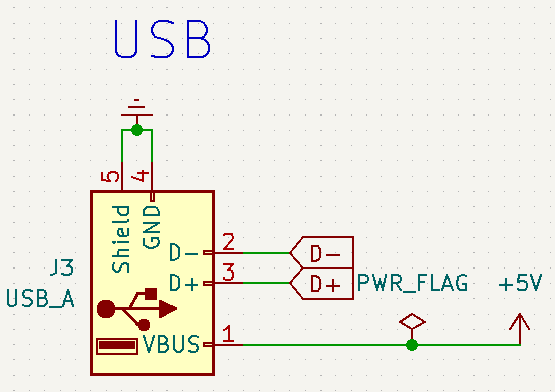
The power is supplied by the VBus (+5V) and the GND (earth) pins. I didn’t understand what was the Shield pin, so I didn’t connect it in a first time. But after checking the work of Onik, I connected it to GND:
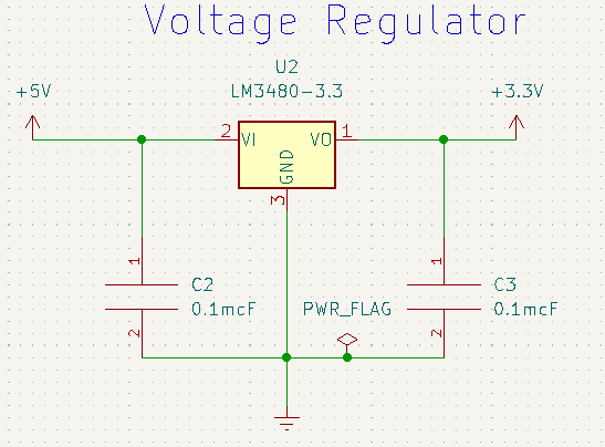
I then drew the voltage regulator circuit. For this, I read the datasheet of the LSM3480:
Then, I sketched the reset button and the built-in LED:
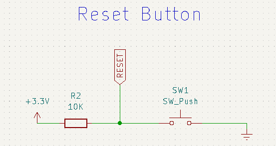
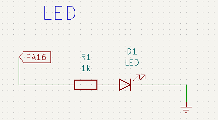
The reason for the higher resistor with the button is probably that the LED already has a resistance.
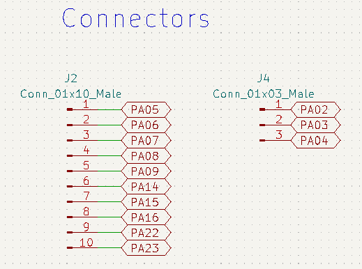
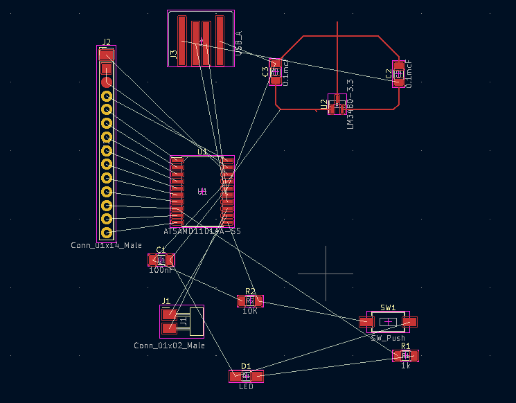
Eventually, I drew the connectors. First, I used a 13 pins connector, but after struggling to route them in the PCB editor, I chose to use different connectors for pins on each side of the microcontroller:
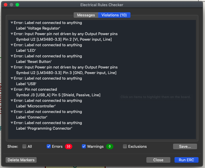
When sketching, I often performed electrical rules checks (ERC):
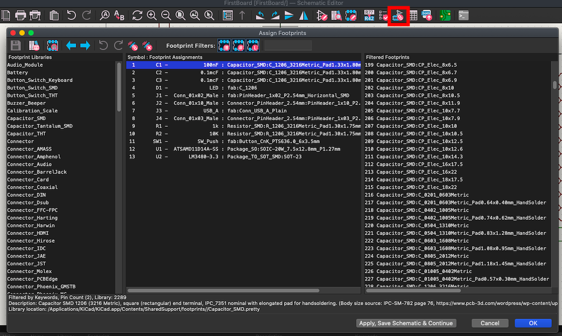
Once everything was well connected, I assigned a footprint for each component of my schematic:
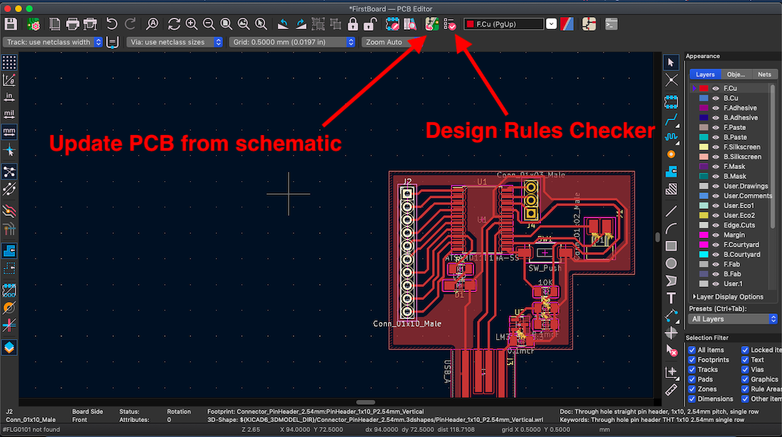
Routing in PCB editor
The next step was to import the schematics:
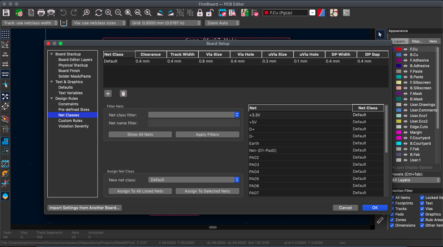
Once I had all my footprints in the PCB editor, I set the width of the tracks. Following the tutorial of the Aalto Fablab in Finland, I chose 0.4mm:
Then, I started to trace some wires:
This routing took me quite some time, with many trials and errors. But in the end, I managed to obtain some result and to solve the errors detected by the DRC (I still had some warnings though):
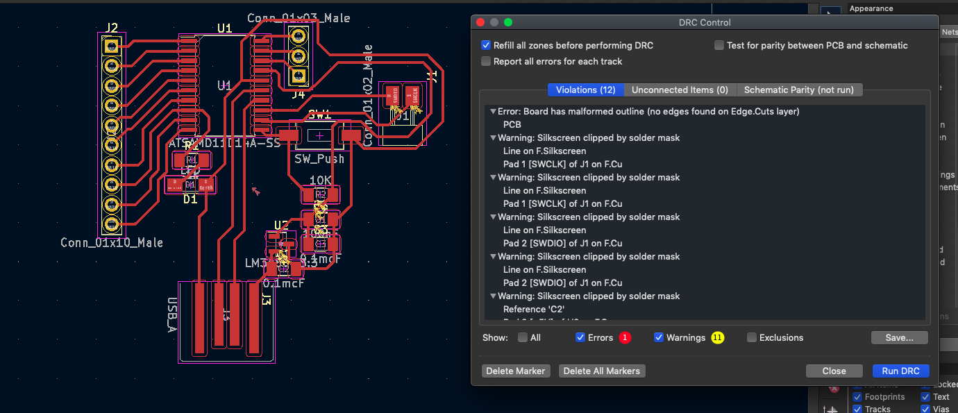
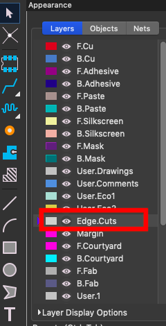
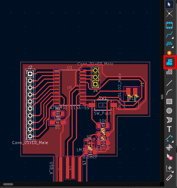
Eventually, I traced the sides of my board using the edge cuts layer:
And then the “Add a filled zone” tool to join all the GND pins together:
After the regional review with Jani and Babken, I learnt that the vertical pinheader I chose was hard to add, since I would need to make holes. I switched them for the corresponding horizontal pinheader. I also had a button that we didn’t have in the Fablab, so I replaced it by the one with four legs.
After running again the DRC, I had two errors. The first one was a clearance error:
![]()
The second one was a courtyard error:
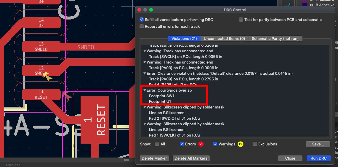
I then obtained the following PCB:
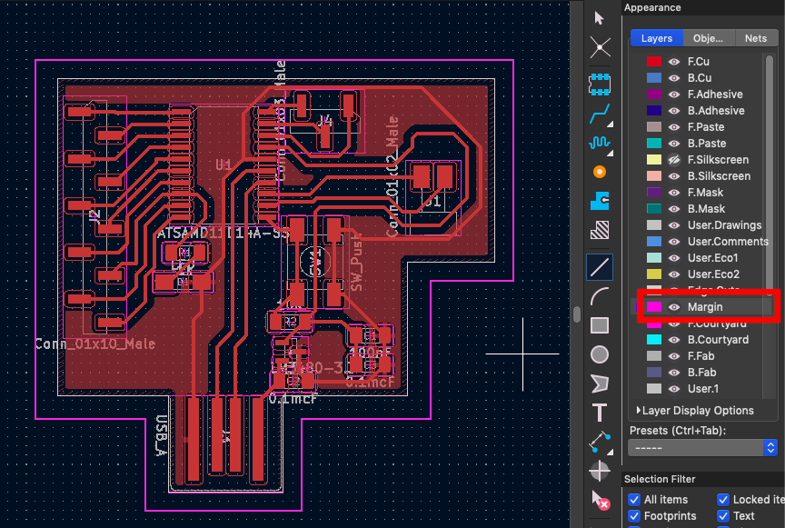
According to the tutorial by Aalto Fablab, in the current state, this design would be a problem for mods. The program wouldn’t be able to cut the external lines. To fix that, I added a margin of 2mm or more. For this, I had to select the “Margin” layer:
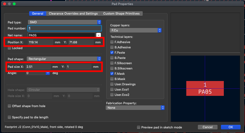
After Babken checked my board, he noticed that the pinheaders I put were still not correct. Since I didn’t find the right one in my library, I directly edited the pad to fit:
He also said that the decoupling capacitor (C1) should be as close as possible to the microcontroller. So I edited my schematic accordingly:
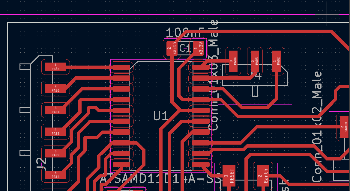
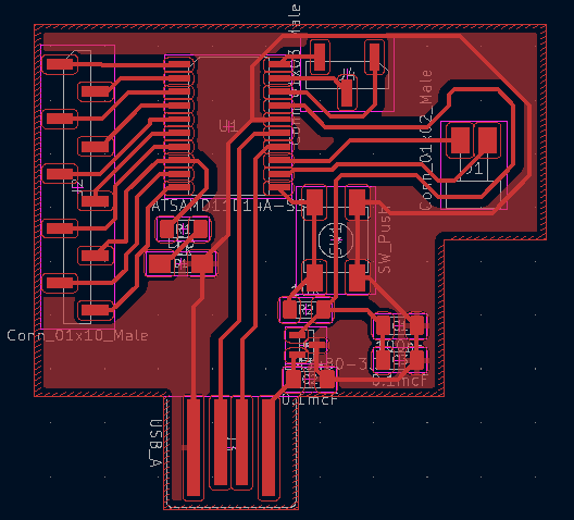
After the regional review with Luke from Agrilab, he said that it is bad practice to have the copper filling coming too close to the USB connector, so I removed it:
![]()
Generating the toolpath with mods
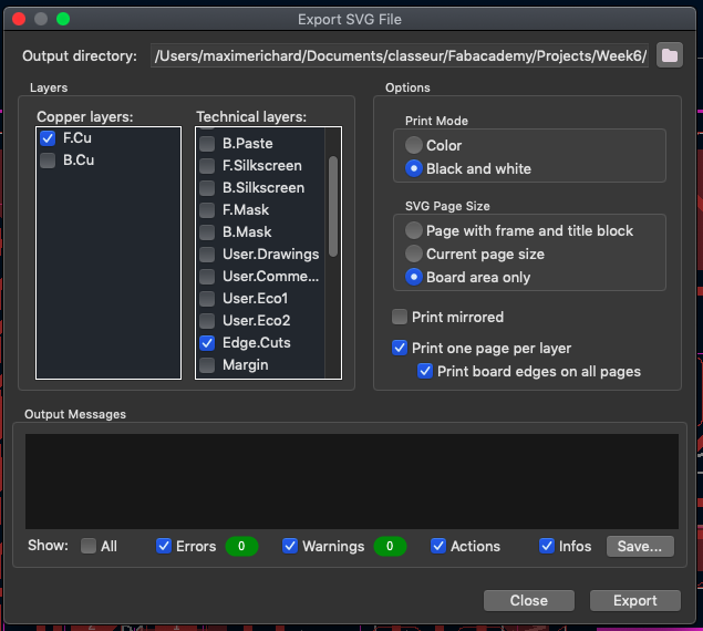
Once I had my board design, I went on to generate the g-code for milling. First, I had to export the drawing as .svg file:
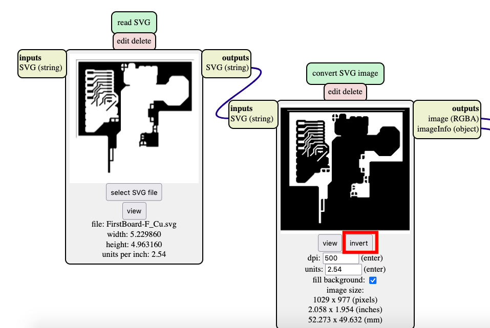
Then, I used mods to generate the toolpath. On the white page, I right-clicked -> programs -> open server program -> PCB svg. Then I selected my .svg file. I had to invert the black and white to obtain the negative of my image:
I then adapted the tool diameter:
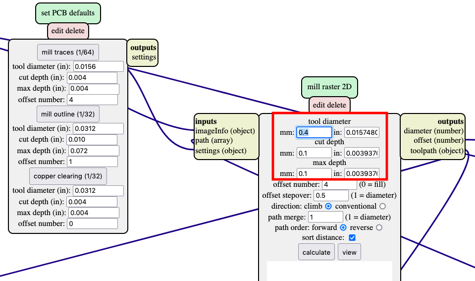
Eventually, I could change the origin as well as the speed of the cutting. I also added a node to save the file:
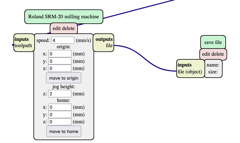
I could then press the “calculate” button in the “mill raster 2D” node to get the file with the toolpath. Aftwerwards, I repeated this process for the cutting layer.
Conclusion
This week had more theoretical content than the previous ones. It was very stimulating for me to try to understand how the different components were working. However, it was a bit frustrating for me at the end of week: I didn’t know if what I designed would even work at all. I’ll have to wait one more week to have the answer to this question…