Week 11: Input devices
✓ measure something: add a sensor to a microcontroller board that you have designed and read it
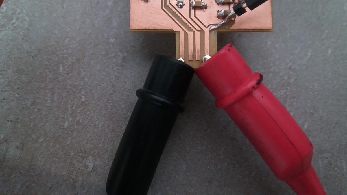
✓ probe an input device’s analog levels and digital signals
A failure
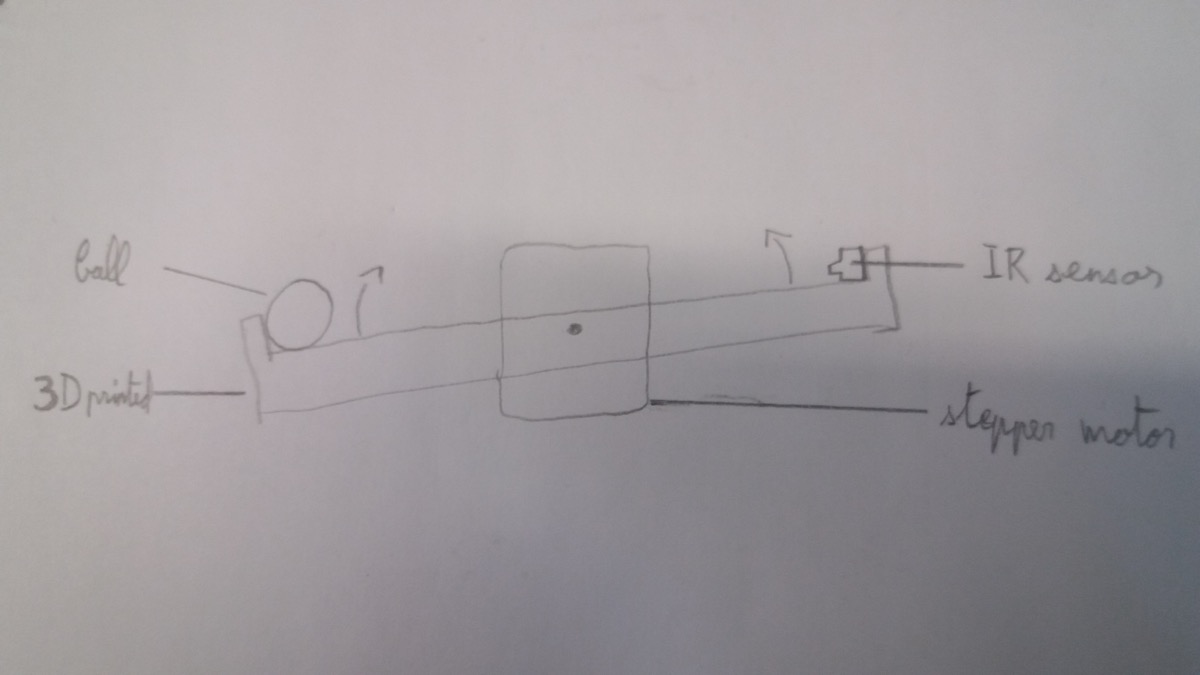
My first idea was to balance a ball on a rail using a microcontroller, a distance sensor and a stepper motor:
Unfortunately, due to some stupid mistakes I made, I fried two distance sensors and ended up giving up on this project. However, I will document here what I did.
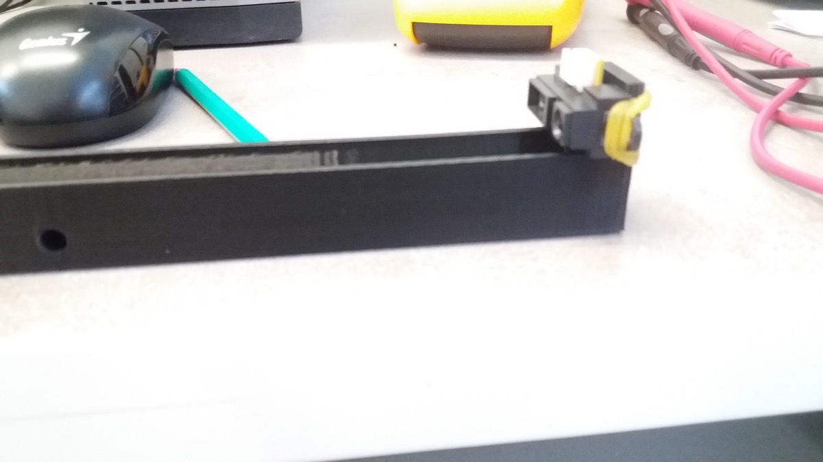
I started by sketching the rail on which the ball would roll:
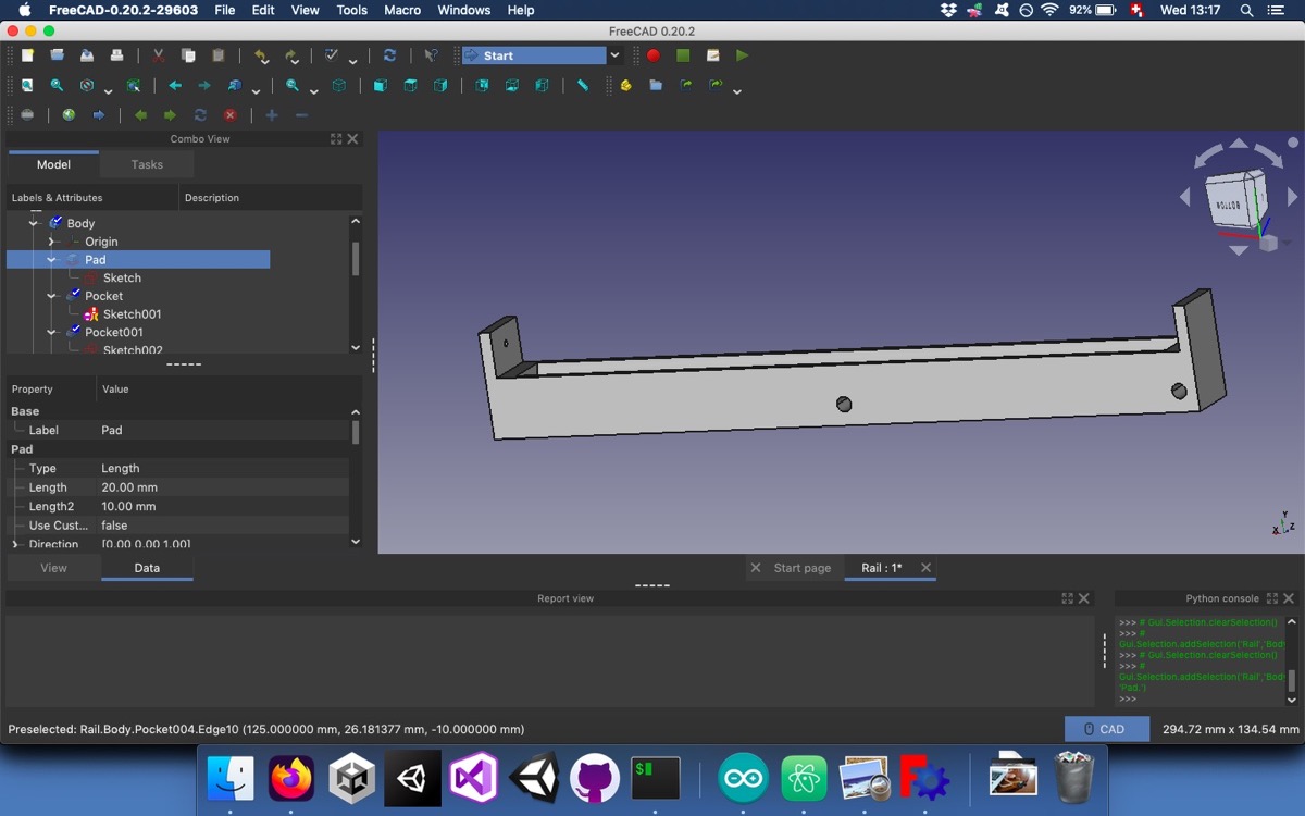
And then I 3D printed it.
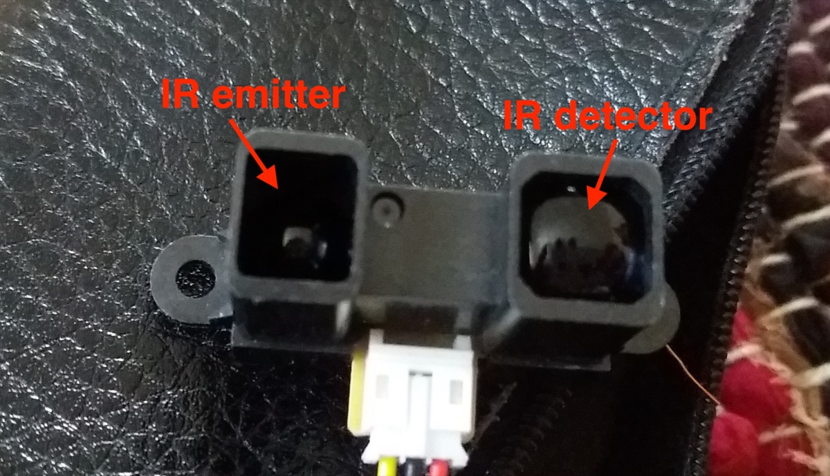
I then got familiar with the distance sensors we had in the lab. I used the Sharp GP2Y0A21YK which is an analogous IR distance sensor with a usable range of 10-80cm. This kind of sensors works by emitting an infrared beam and by using a Position Sensing Device which measures the angle at which the returning beam hits the sensor.
Since it’s an analogous sensor, it returns a continuous voltage between a specified range. In the case of this sensor, the range with an +5V input is comprised between 0.25V and 0.55V (tested with a white sheet of paper between 10 and 80 cm):
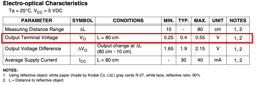
This voltage is then mapped to an integer between 0 and 1023. The code I used to test this sensor is the following:
void setup() {
  // put your setup code here, to run once:
  //Initialize input pins
  pinMode(2, INPUT);

  Serial.begin(9600);
}

void loop() {
  // put your main code here, to run repeatedly:
  uint16_t input = analogRead(2);     //read the pin 2
  Serial.println(input);
  delay(500);
}
Once I was able to use this sensor, I put it on my 3D printed rail and used some rubber bands to prevent it from moving:
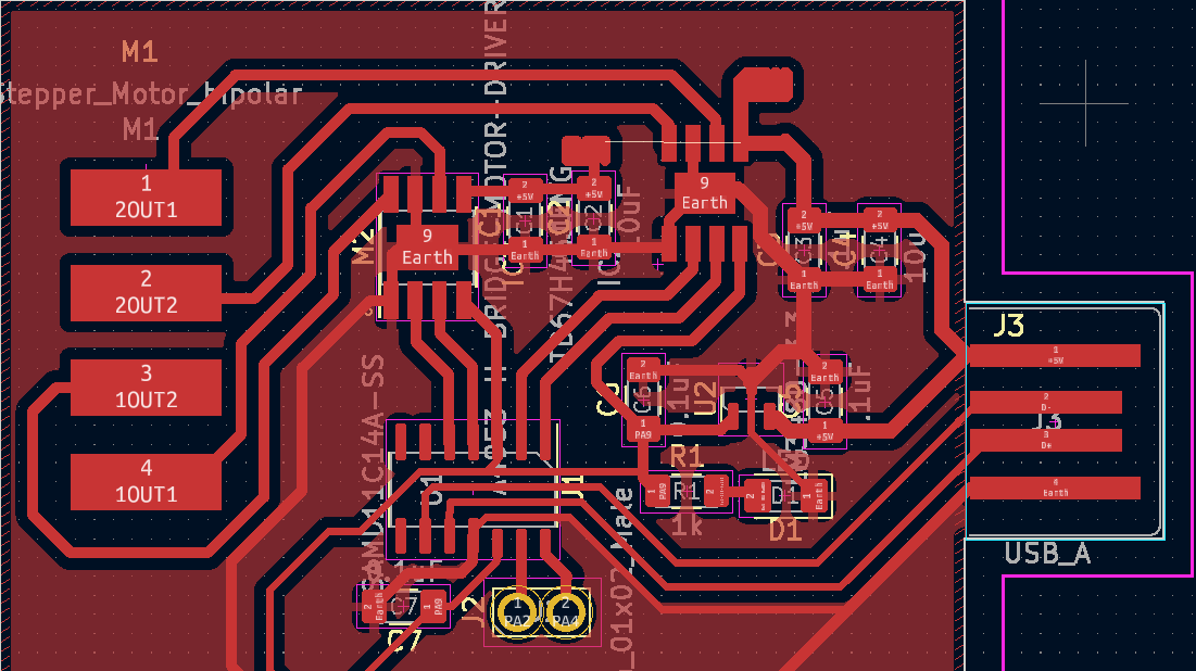
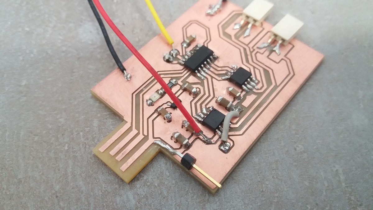
I proceeded to add the stepper motor. For this, I used the board I made during the Output week:
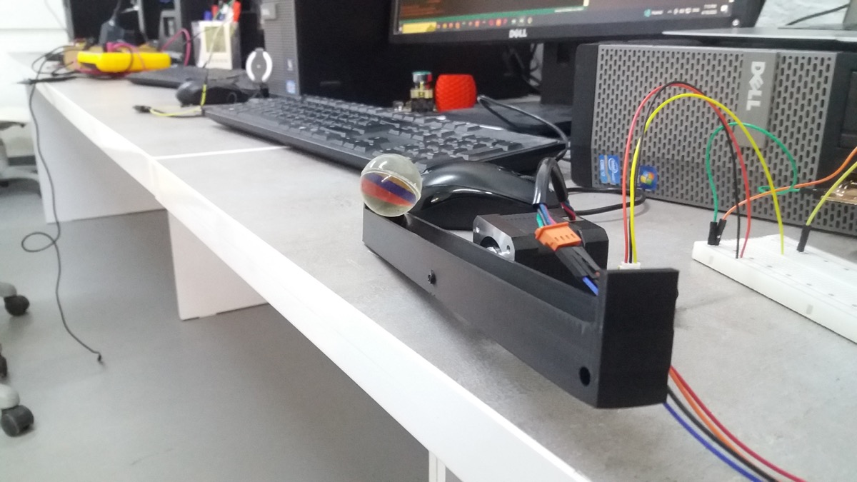
I mounted my 3D printed rail on the motor:
I then started to code. I started with the same code from Neil that I used during the output week and modified it. Here is the modified part:
...

void setup() {
  //
  // initialize H-bridge pins
  //
  clear(A1pin);
  output(A1pin);
  clear(A2pin);
  output(A2pin);
  clear(B1pin);
  output(B1pin);
  clear(B2pin);
  output(B2pin);

  //Initialize input pins
  pinMode(2, INPUT);

  Serial.begin(9600);
}

uint16_t averageInput = 0;
uint8_t averageCount = 50;
uint8_t updateCount = 100;
uint16_t previousPos = 0;
int16_t ballSpeed = 0;

int8_t rotation = 0;
int8_t previousRotation = 0;

void loop() {
  //
  // main loop
  //
  while (1) {
    uint16_t input = analogRead(2);     //read the pin 2
    averageInput = (averageInput * (averageCount - 1) + input) / averageCount;    //compute an average of the last 50 input reads
    averageInput = input;

    updateCount--;

    if (updateCount <= 0) {
      ballSpeed = averageInput - previousPos;
      previousPos = averageInput;
      if (averageInput > 505 && !(ballSpeed < 0)) {   // if the ball is too close to the sensor, turn the motor clockwise
        rotation = 1;
        for (uint8_t i = 0; i < 2; i++) {
          step_half_cw();
        }
        delay(100);
      } else if (averageInput < 495 && !(ballSpeed > 0)) {  // if the ball is too far from the sensor, turn the motor counterclockwise
        rotation = -1;
        for (uint8_t i = 0; i < 2; i++) {
          step_half_ccw();
        }
        delay(100);
      } else {
        rotation = 0;
      }
      Serial.print("average input: ");
      Serial.println(averageInput);
      Serial.print("ballSpeed: ");
      Serial.println(ballSpeed);
      if (previousRotation != rotation) {
        Serial.print("NEW ROTATION: ");
        Serial.println(rotation);
        previousRotation = rotation;
      }

      updateCount = 1;

    }
  }
}
I chose an arbitrary value for the distance sensor. 500 seemed to correspond to about 10-15 cm from the sensor. I then had to power the stepper motor and here I made a big mistake. During the output week, I powered my motor like this:
I used the adjustable power supply from the lab. 8V were sufficient to power the motor I used during the ouptut week. However, the shaft was small and the motor was too close to the rail, which prevented the ball to roll past the motor. To solve this issue, the easiest solution was to use a slightly bigger motor with a longer shaft:
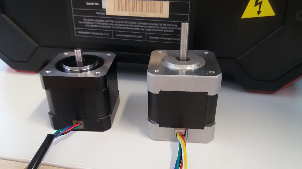
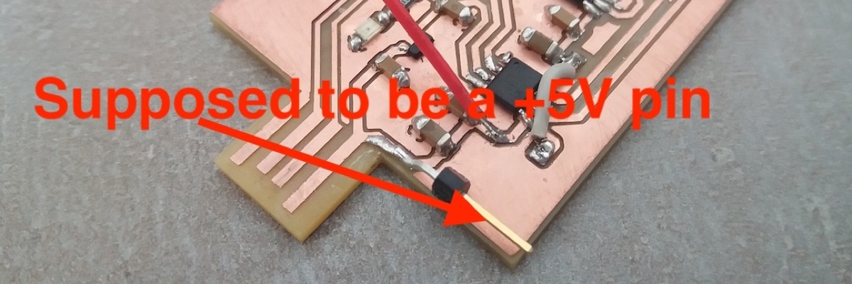
This motor (on the right) cannot work with 8V, so I increased the voltage until it was moving properly, which turned out to be 18-20V. The big problem that I stupidly didn’t anticipate was that the pin powering my sensor, which was supposed to provide 5V, was now at the same voltage as my motor (18V).
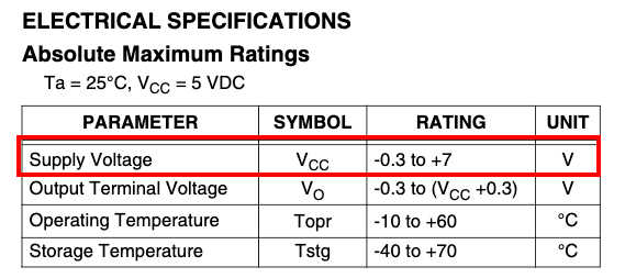
I made few trials, and the results were not satisfying. Most of the time, the motor would start turning in the right direction, but then it wouldn’t stop. It was hard to debug, because I had to unplug my microcontroller from my computer to test the code, and I didn’t have any logging during my tests. Furthemore, on my MacBook, the Arduino IDE has trouble recognizing the boards and once it’s plugged, it needs a couple of minutes until I see it in my IDE. Each trial was painfully long! After a couple of back and forth between my computer and the power supply, the sensor started to not work properly. I thought that this sensor was not good from the beginning, since it didn’t seem to behave exactly as it should be, according to the graph found on this page. Indeed, it seemed like the output voltage would keep increasing even at short distances. I changed the sensor, not understanding that I caused the defect of the sensor (Why!?). The next sensor seemed to work better than the first one. Unfortunately, after a couple of trials, some smoke came out of the sensor. I finally understood that the voltage applied wasn’t appropriate for the sensor:
After realising my mistakes, and because I didn’t really know how do it correctly with confidence, I abandoned the idea of balancing a ball with a stepper motor.
I took a last picture of the corpses of my sensors:
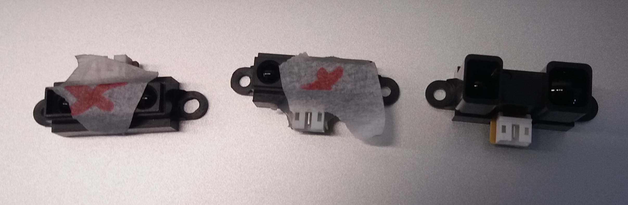
I put the sensor I would use later next to his fallen comrades, so that he would know what awaits him in case he doesn’t behave…
My original idea was to implement a PID controller. I checked this page and watched this video to understand how to do it. Well, it’ll be for another time.
A distance scanner
After giving up on my PID project, I resolved to mount the distance sensor on a servo to scan a portion of the environment and detecting close objects. I used a slightly different IR sensor: Sharp 2Y0A02, which works from 20 to 150cm.
A misadventure with my board
Since I didn’t need the stepper motor, I chose to use the board I made during the electronic production week. Unfortunately, when I was uploading a sketch to it, it caused an error and it was afterwards not properly recognised by my MacBook:
Maximes-MacBook-Air:~ maximerichard$ ioreg -p IOUSB
+-o Root  <class IORegistryEntry, id 0x100000100, retain 15>
  +-o AppleUSBXHCI Root Hub Simulation@14000000  <class AppleUSBRootHubDevice, $
    +-o BRCM20702 Hub@14300000  <class AppleUSBDevice, id 0x100000356, register$
    | +-o Bluetooth USB Host Controller@14330000  <class AppleUSBDevice, id 0x1$
    +-o D11D14AS@14100000  <class AppleUSBDevice, id 0x100000d26, registered, !$
Maximes-MacBook-Air:~ maximerichard$
Maximes-MacBook-Air:~ maximerichard$ ioreg -p IOUSB
+-o Root  <class IORegistryEntry, id 0x100000100, retain 15>
  +-o AppleUSBXHCI Root Hub Simulation@14000000  <class AppleUSBRootHubDevice, $
    +-o BRCM20702 Hub@14300000  <class AppleUSBDevice, id 0x100000356, register$
    | +-o Bluetooth USB Host Controller@14330000  <class AppleUSBDevice, id 0x1$
    +-o Internal Memory Card Reader@14600000  <class AppleUSBDevice, id 0x10000$
I managed to install a bootloader again and it was recognised again. However, the serial communication was fairly unstable so I resolved to use the same board as for the stepper motor.
Raw data to distance
In order to understand how to convert the raw data (integer between 0 and 1023) into a distance, I read this page.
The problem I faced while applying the formula given in this page is that I didn’t find out how to use a double or a float in my sketch. As soon as I am using one, the compiler tells me that the sketch doesn’t fit on my board. I tried to translate the code into using only integers:
void setup() {
  // put your setup code here, to run once:
  pinMode(7, INPUT);

  Serial.begin(9600);
}

void loop() {
  // put your main code here, to run repeatedly:
  uint16_t input = analogRead(7);
  uint16_t computed = 2584 - 20 * input + 717 / 10000 * input * input - 1 / 10000 * input * input * input + 7 / 1000000000 * input * input * input * input;
  Serial.println(input);
  Serial.print("computed: ");
  Serial.println(computed);

  delay(500);
}
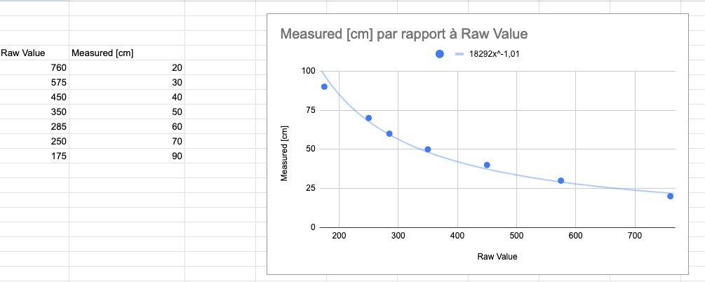
This code wasn’t working properly. It was giving very high number whatever the raw input data. This was probably due to the approximation I made. I corrected this issue and it gave more appropriate data, but it was way off compared to reality. I don’t really know why… maybe the sensor is slightly different?
I therefore had to calibrate it myself:
Scanning with servo
Final scanning code:
//
// hello.servo-registers.D11C.ino
//
// D11C servo hello-world, registers version
//
// Neil Gershenfeld 11/6/22
//
// This work may be reproduced, modified, distributed,
// performed, and displayed for any purpose, but must
// acknowledge this project. Copyright is retained and
// must be preserved. The work is provided as is; no
// warranty is provided, and users accept all liability.
//

void setup() {
  //
  // set up PWM
  //
  GCLK->GENCTRL.reg = GCLK_GENCTRL_ID(4) | // use clock generator 4
                      GCLK_GENCTRL_GENEN | // enable clock generator
                      GCLK_GENCTRL_SRC_DFLL48M | // 48MHz source
                      GCLK_GENCTRL_IDC; // 50-50 duty cycle
  while (GCLK->STATUS.bit.SYNCBUSY); // sync
  GCLK->GENDIV.reg = GCLK_GENDIV_DIV(1) | // divide by 1
                     GCLK_GENDIV_ID(4); // apply to GCLK4
  while (GCLK->STATUS.bit.SYNCBUSY); // sync
  GCLK->CLKCTRL.reg = GCLK_CLKCTRL_CLKEN | // enable clock control
                      GCLK_CLKCTRL_GEN_GCLK4 | // select GCLK4
                      GCLK_CLKCTRL_ID_TCC0; // connect to TCC0
  while (GCLK->STATUS.bit.SYNCBUSY); // sync
  TCC0->CTRLA.reg |= TCC_CTRLA_PRESCALER(TCC_CTRLA_PRESCALER_DIV1_Val); // divide by 1
  TCC0->WAVE.reg = TCC_WAVE_WAVEGEN_NPWM; // normal PWM
  while (TCC0->SYNCBUSY.bit.WAVE); // sync
  TCC0->PER.reg = 48e6 / 50; // 48 MHz/50 Hz period
  while (TCC0->SYNCBUSY.bit.PER); // sync
  TCC0->CC[1].reg = 0; // compare WO[1] for PA05
  while (TCC0->SYNCBUSY.bit.CC1); // sync
  PORT->Group[PORTA].DIRSET.reg = PORT_PA05; // set pin output
  PORT->Group[PORTA].OUTCLR.reg = PORT_PA05; // set pin low
  PORT->Group[PORTA].PINCFG[5].reg |= PORT_PINCFG_PMUXEN; // enable port mux
  PORT->Group[PORTA].PMUX[2].reg = PORT_PMUX_PMUXO_F; // connect pin 2*2+1 to TCC0
  TCC0->CTRLA.reg |= (TCC_CTRLA_ENABLE); // enable TCC
  while (TCC0->SYNCBUSY.bit.ENABLE); // sync


  //Distance sensor stuffs
  pinMode(2, INPUT);

  Serial.begin(9600);
}

void loop() {
  //
  // rotate servo between limits
  //
  uint32_t minimum = 48e6 * 0.5e-3; // 0.5 ms at 48 MHz
  uint32_t maximum = 48e6 * 2.5e-3; // 2.5 ms at 48 MHz

  uint16_t stepCount = 18;
  uint32_t stepSize = (maximum - minimum) / stepCount;

  for (uint16_t i = 0; i < stepCount; i++) {
    TCC0->CC[1].reg = minimum + stepSize * i;
    ScanDistance(i * 10);
    delay(500);
  }

  for (uint16_t i = 2; i < stepCount; i++) {
    TCC0->CC[1].reg = maximum - stepSize * i;
    ScanDistance(180 - i * 10);
    delay(500);
  }
}

void ScanDistance(uint16_t angle) {
  uint16_t input = analogRead(2);
  uint16_t computed = 18292 / (input * 101 / 100);
  Serial.print("/*KAANSATQRO,");
  Serial.print(angle);
  Serial.print(",");
  Serial.print(computed);
  Serial.println("*/");
}
In order to visualise my input, I used Serial Studio:
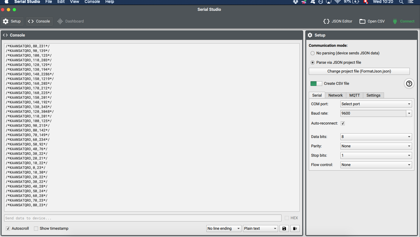
JSON code for Serial Studio:
{
    "frameEnd": "",
    "frameStart": "",
    "groups": [
        {
            "datasets": [
                {
                    "alarm": 0,
                    "fft": false,
                    "fftSamples": 128,
                    "graph": true,
                    "led": false,
                    "log": false,
                    "max": 180,
                    "min": 0,
                    "title": "Angle",
                    "units": "°",
                    "value": "%2",
                    "widget": ""
                },
                {
                    "alarm": 0,
                    "fft": false,
                    "fftSamples": 128,
                    "graph": true,
                    "led": false,
                    "log": false,
                    "max": 400,
                    "min": 0,
                    "title": "Distance",
                    "units": "cm",
                    "value": "%3",
                    "widget": ""
                }
            ],
            "title": "Rotating scanner",
            "widget": ""
        }
    ],
    "separator": ",",
    "title": "%1"
}
Group assignment
During this group assignment, we used some oscilloscope to test several input devices.
Rheostat
A rheostat is device that enables us to change the resistance using a knob. We used a multimeter to measure the resistance while turning the knob. It was rated at 20kOhm but when we measured, it was going from 8kOhm to 17.8kOhm.
Photoresistor
A photoresistor is similar to a rheostat, but instead of changing the resistance mechanically, the resistance changes with the amount of light hitting the device (the more light, the less resistance).
Personal reflection
During this group assignment, we measured both analog and digital input devices. Analog devices need to be plugged into pins that are able to read analog signals. For example, on the SAMD11C the suitable pins would be the following:
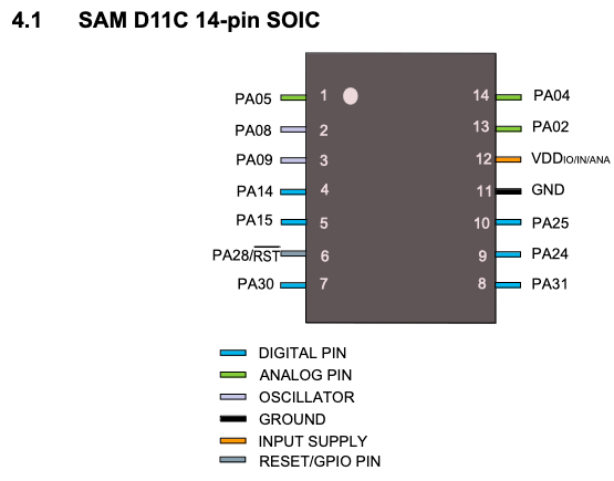
Digital device aren’t read by measuring a voltage difference but by reading pulse duration and frequency.
I found the technology of the IR distance sensor very interesting. It sends out an IR signal and measures the intensity of this signal coming back to the sensor. In order to discriminate the energy coming from the outgoing signal and the energy coming from ambient noise, it modulates the signal with a carrying wave and, when it comes back to the sensor, it demodulates to extract the remaining signal.
Conclusion
I was quite frustrated by how this week started. Frying two sensors the same way before realising my mistake was quite enraging. At least, I used an important lesson and hope that I will never make this mistake again.
Once I decided to greatly simplify my project, I expected the workflow to be very straight forward. I was surprised that I couldn’t find some reliable conversion table (raw data to distance) for my sensor. However, this was not a big deal and it was interesting to come up with a conversion function by myself.
Files
Freecad file for the abandoned project