Week 13: Networking and Communications
✓ design, build, and connect wired or wireless node(s) with network or bus addresses
✓ send a message between two projects
SAMD11D14 as a USB peripheral
As I didn’t manage to make my gamepad work last week, I continued this endeavour at the beginning of this week.
I was very lucky, since the lecture on Wednesday gave me a hint about how to proceed. Indeed, inside the chapter of wired communication, Neil talked about USB connections. He even linked some library for Arduino HID projects, which saved me A LOT of time. This project even has a wiki which explains how to proceed with the library.
USB HID stands for “USB human interface device” and specifies how keyboards, mice, game controllers and some other peripherals should interact with the computer.
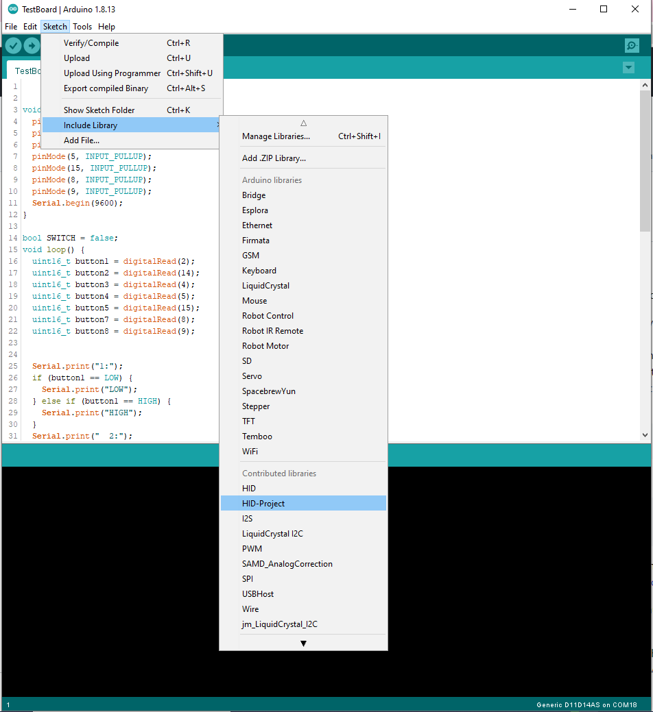
It was easy to install the library inside the Arduino IDE:
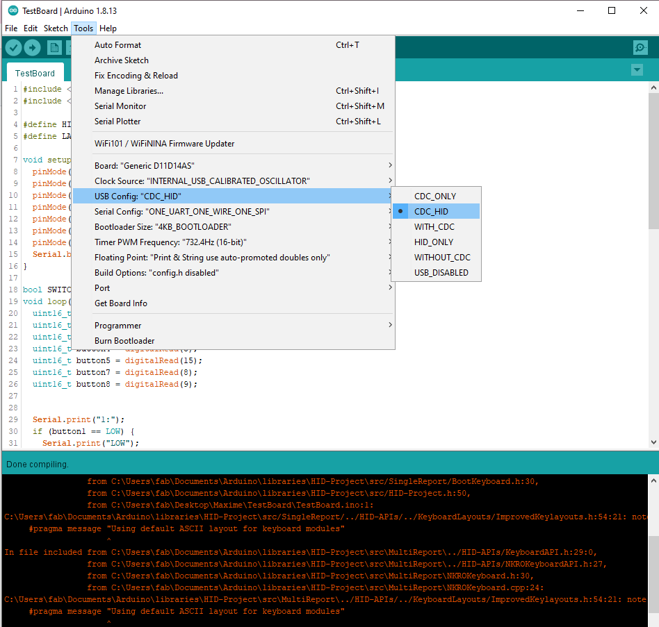
I also had to change the USB config in Tools:
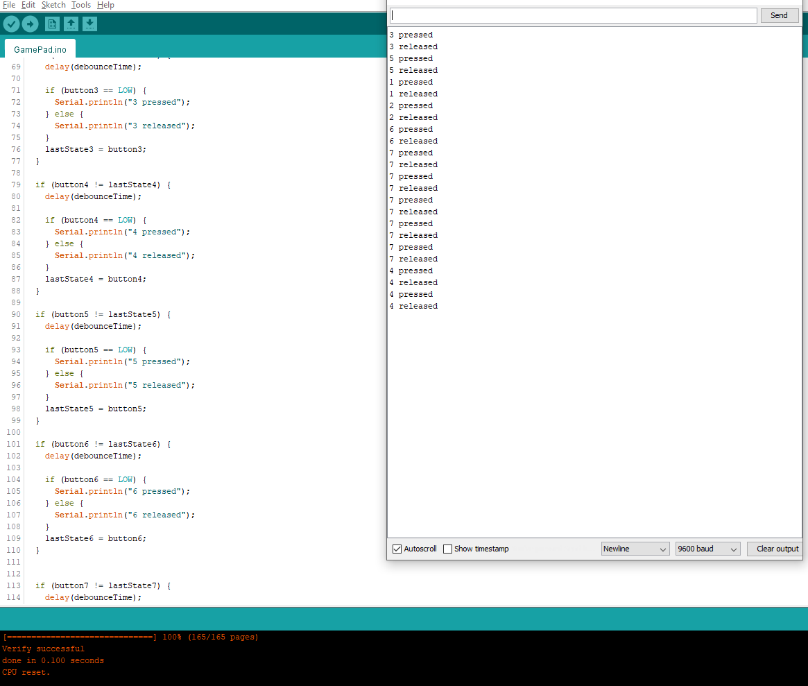
I could then test the library and its use was not very complicated:
Once I added all the buttons, I had some problem with the available space:
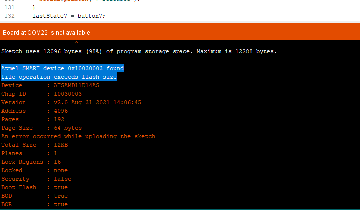
I had to remove all the serial logging and transformed all my “int” variables into “uint8_t”.
I was eventually able to write a working program for my gamepad:
#include <HID-Project.h>
#include <HID-Settings.h>

#define HID_CUSTOM_LAYOUT
#define LAYOUT_GERMAN

#define BUTTON1 2
#define BUTTON2 4
#define BUTTON3 15
#define BUTTON4 5
#define BUTTON5 8
#define BUTTON6 9
#define BUTTON7 14

uint8_t lastState1;
uint8_t lastState2;
uint8_t lastState3;
uint8_t lastState4;
uint8_t lastState5;
uint8_t lastState6;
uint8_t lastState7;

uint8_t debounceTime = 10;

void setup() {
  pinMode(BUTTON1, INPUT_PULLUP);       //I've added some resistor on buttons, so I shouldn't need INPUT_PULLUP, but some pins started working after I added them...
  pinMode(BUTTON2, INPUT_PULLUP);
  pinMode(BUTTON3, INPUT_PULLUP);
  pinMode(BUTTON4, INPUT_PULLUP);
  pinMode(BUTTON5, INPUT_PULLUP);
  pinMode(BUTTON6, INPUT_PULLUP);
  pinMode(BUTTON7, INPUT_PULLUP);
  Serial.begin(9600);
}

bool SWITCH = false;
void loop() {
  uint8_t button1 = digitalRead(BUTTON1);
  uint8_t button2 = digitalRead(BUTTON2);
  uint8_t button3 = digitalRead(BUTTON3);
  uint8_t button4 = digitalRead(BUTTON4);
  uint8_t button5 = digitalRead(BUTTON5);
  uint8_t button6 = digitalRead(BUTTON6);
  uint8_t button7 = digitalRead(BUTTON7);

  if (button1 != lastState1) {
    delay(debounceTime);

    if (button1 == LOW) {
      //Serial.println("1 pressed");
      Keyboard.press(KEY_LEFT_ARROW);
    } else {
      Keyboard.release(KEY_LEFT_ARROW);
      //Serial.println("1 released");
    }
    lastState1 = button1;
  }

  if (button2 != lastState2) {
    delay(debounceTime);

    if (button2 == LOW) {
      Keyboard.press(KEY_DOWN_ARROW);
      //Serial.println("2 pressed");
    } else {
      Keyboard.release(KEY_DOWN_ARROW);
      //Serial.println("2 released");
    }
    lastState2 = button2;
  }

  if (button3 != lastState3) {
    delay(debounceTime);

    if (button3 == LOW) {
      Keyboard.press(KEY_RIGHT_ARROW);
      //Serial.println("3 pressed");
    } else {
      Keyboard.release(KEY_RIGHT_ARROW);
      //Serial.println("3 released");
    }
    lastState3 = button3;
  }

  if (button4 != lastState4) {
    delay(debounceTime);

    if (button4 == LOW) {
      Keyboard.press(KEY_UP_ARROW);
      //Serial.println("4 pressed");
    } else {
      Keyboard.release(KEY_UP_ARROW);
      //Serial.println("4 released");
    }
    lastState4 = button4;
  }

  if (button5 != lastState5) {
    delay(debounceTime);

    if (button5 == LOW) {
      Keyboard.press(KEY_C);
      //Serial.println("5 pressed");
    } else {
      Keyboard.release(KEY_C);
    }
    lastState5 = button5;
  }

  if (button6 != lastState6) {
    delay(debounceTime);

    if (button6 == LOW) {
      Keyboard.press(KEY_V);
      //Serial.println("6 pressed");
    } else {
      Keyboard.release(KEY_V);
    }
    lastState6 = button6;
  }


  if (button7 != lastState7) {
    delay(debounceTime);

    if (button7 == LOW) {
      Keyboard.press(KEY_X);
      //Serial.println("7 pressed");
    } else {
      Keyboard.release(KEY_X);
    }
    lastState7 = button7;
  }
}
The library can also manage gamepad inputs, but I used the keyboard keys, since it was more straight forward for testing. I could test it with a game and it worked:
The buttons were very hard to press and this makes the gamepad not really useable. A fix could be maybe to have a thinner layer of rubber on top of the buttons.
I2C between SAMD11C and ATTINY1614
Making the board
For this week, I wanted to establish an I2C communication between two microcontrollers. I chose a SAMD11C that I already used and an ATTINY1614, because I never used this kind of microcontrollers. It was also a good opportunity to discover a new architecture, since the SAMD is ARM and the ATTINY is AVR, and a new programming workflow, since I couldn’t use SWD for the ATTINY.
I chose to put both microcontrollers on the same PCB, which is probably a bad practice, since if one of them has problems, the whole board must be discarded. However, it seemed to be like a good challenge for learning and I would have to carve and cut only one board.
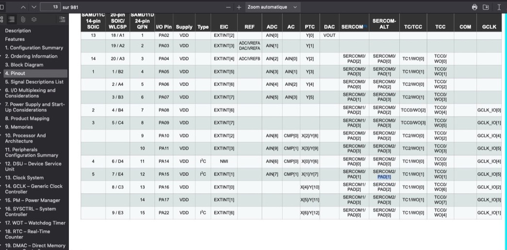
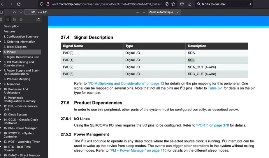
The first step was to identify the pins used for the I2C communication: SDA (serial data line) and SCL (serial clock line). I used the following tables from the datasheet of the SAMD11C to identify the pins 4 and 5:
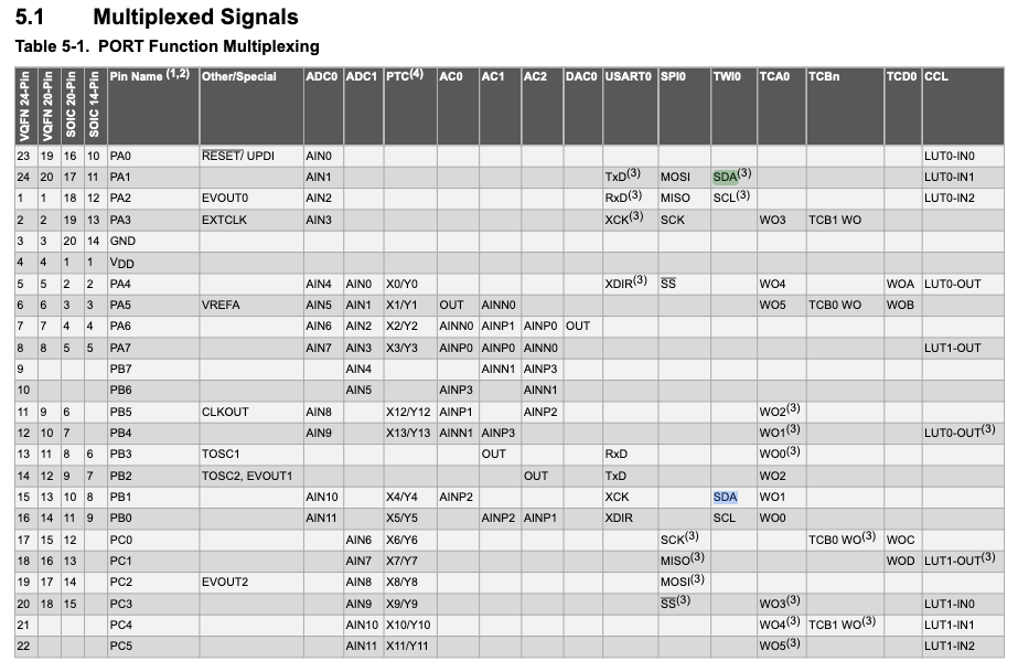
It was more straight forward for the ATTINY1614 since these informations were available in one single table:
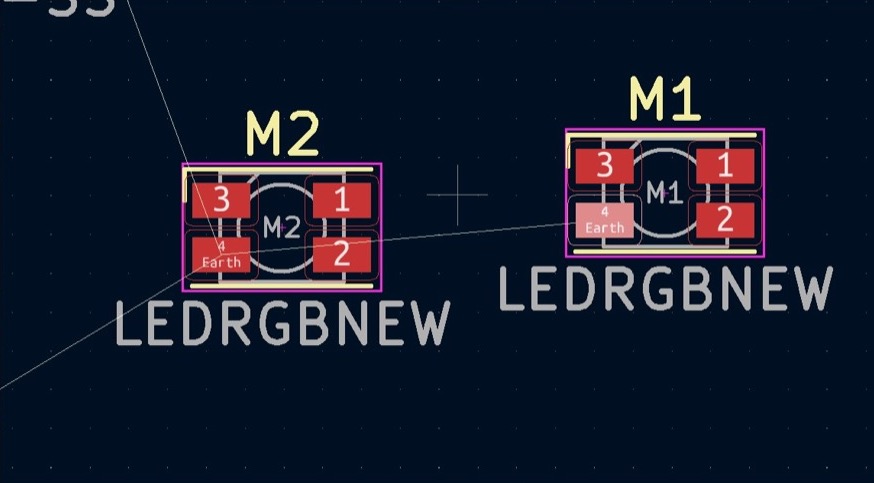
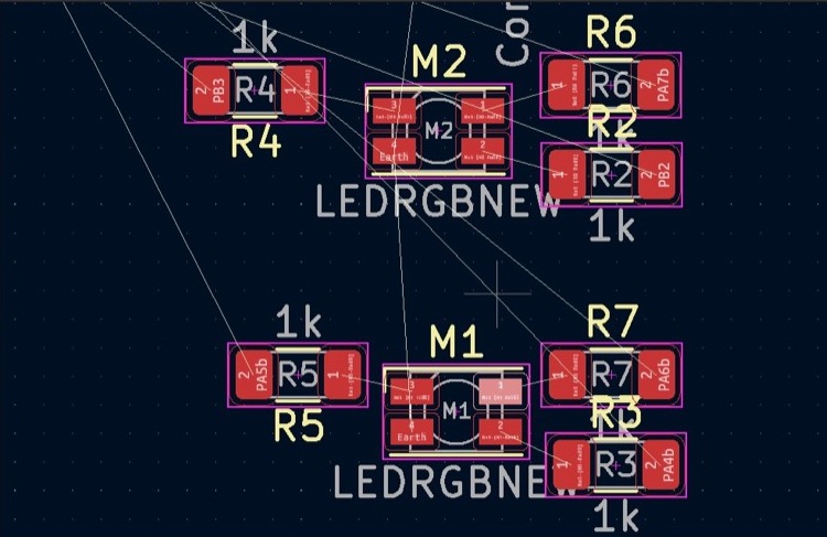
I could then draw the schematic of my board and do the routing as I did during the past weeks. I had some weird issue this time: I wanted to add some RGB LEDs and apparently, there was a problem since the pads in the PCB design program didn’t show their connections to the other components:
I had to add these connections manually:
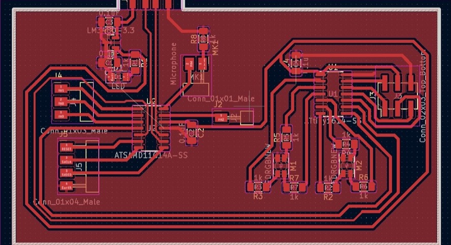
After some efforts, I could do the routing, but I had some unconnected Grounds. I decided to leave it like this and add some 0 Ohm resistors afterwards:
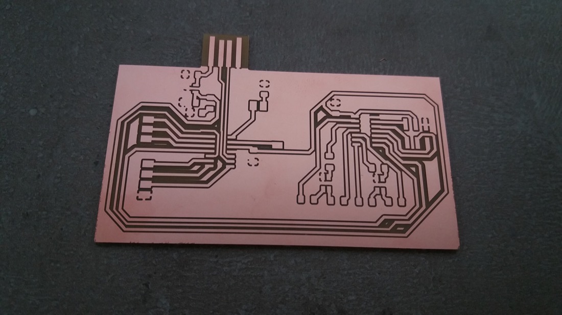
I flattened the MDF sacrificial table with a 6mm flat endmill and this time, I didn’t have any problem with some partially carved part of the board. It came out fine on the first try:
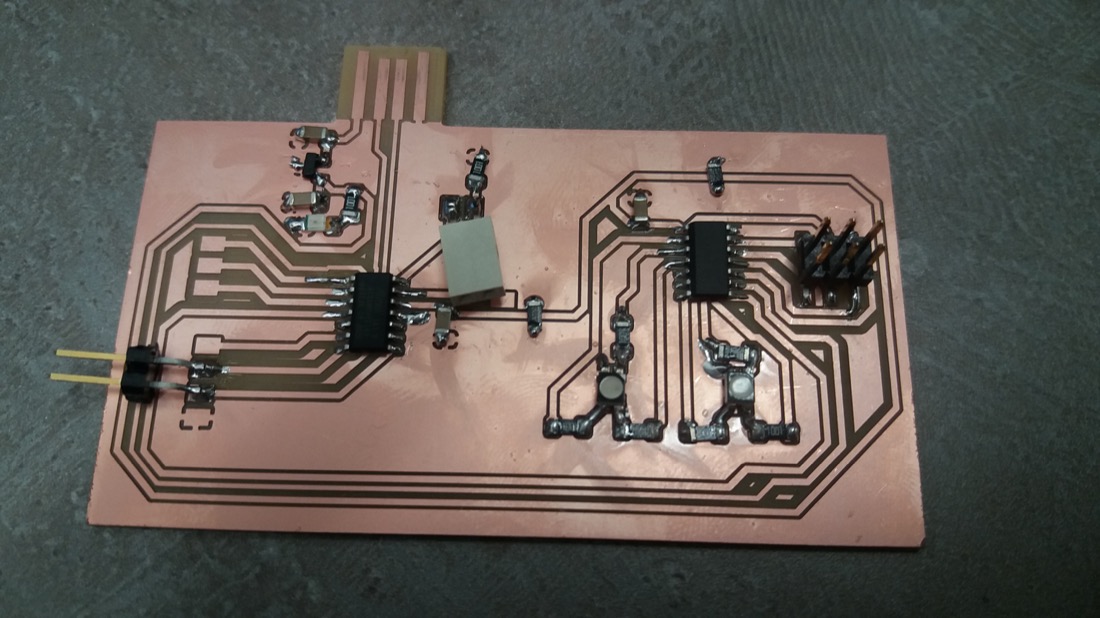
I then soldered the components:
Blinking LEDs
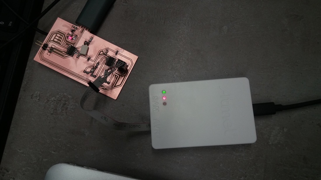
To program the ATTINY1614, I needed some different programmer than the one I used for the SAMD11s. I used the atmel ICE:
I also had to install the software Atmel Microship Studio, which is an IDE. Since I saw that some ATTINY microcontrollers could be programmed using the SPI, I designed my board to have the corresponding pins available for this protocol:

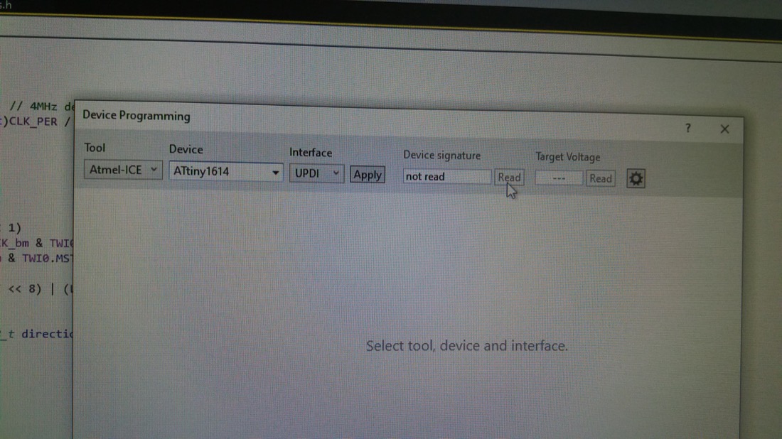
However, I was wrong and it turned out that not all ATTINY microcontroller seem to be programmable using the SPI protocol. Indeed, inside Microchip Studio, in device programming:
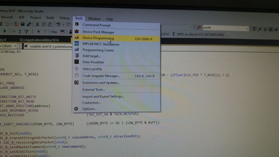
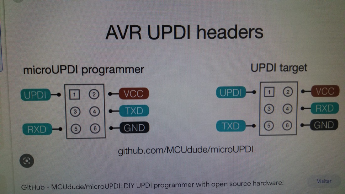
once I selected the Atmel ICE programmer and the ATTINY1614, I could only select the UPDI protocol as Interface:
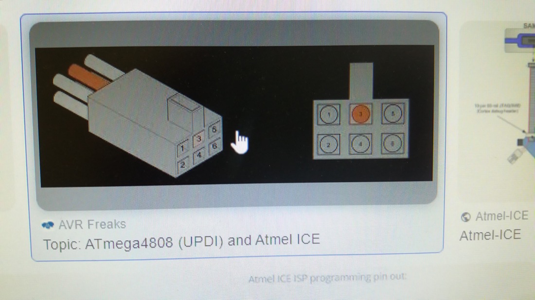
I didn’t expect this and I first thought that my connector was totally useless. Fortunately, the UPDI protocol uses only three pins and they were all available from my connector.

However, I struggled for a long time to find the right connections. I finally stumbled upon these images who allowed me to understand which way I plug the wires by matching the pin numbers:
And here is how it looks like in reality:
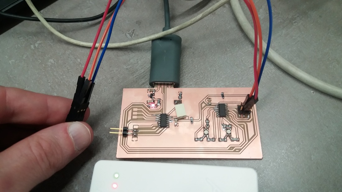
Once the connections were right, I could upload some code! I thought that the most difficult part was behind, but I was very wrong…
I tried to follow few tutorials but somehow, the codes they were providing didn’t work on my case. For example, this series of videos gives a great introduction for programming MCUs very close to the hardware. However, I wasn’t able to compile the code it was providing. After many trials, I followed the code from here in the “Atmel Studio with ATtiny817 Xplained Mini” section and I was able to set some pins HIGH:
#include <avr/io.h>
#define F_CPU 1000000u
#include <util/delay.h>

int main (void)
{
  /* Configure LEDs pin as output */
  PORTA.DIRSET = PIN4_bm;
  PORTA.DIRSET = PIN5_bm;
  PORTA.DIRSET = PIN6_bm;
  PORTA.DIRSET = PIN7_bm;
  PORTB.DIRSET = PIN2_bm;
  PORTB.DIRSET = PIN3_bm;

  while (1)
  {
    /* LEDs on */
    PORTA.OUTSET = PIN4_bm;
    PORTA.OUTSET = PIN5_bm;
    PORTA.OUTSET = PIN6_bm;
    PORTA.OUTSET = PIN7_bm;
    PORTB.OUTSET = PIN2_bm;
    PORTB.OUTSET = PIN3_bm;
    _delay_ms(7000);
    /* LEDs off */
    PORTA.OUTCLR = PIN4_bm;
    PORTA.OUTCLR = PIN5_bm;
    PORTA.OUTCLR = PIN6_bm;
    PORTA.OUTCLR = PIN7_bm;
    PORTB.OUTCLR = PIN2_bm;
    PORTB.OUTCLR = PIN3_bm;
    _delay_ms(7000);
  }
}
There was some problem with my RGB LEDs (datasheet) and they didn’t turn on, but I was able to check that the pins were HIGH using a multimeter:
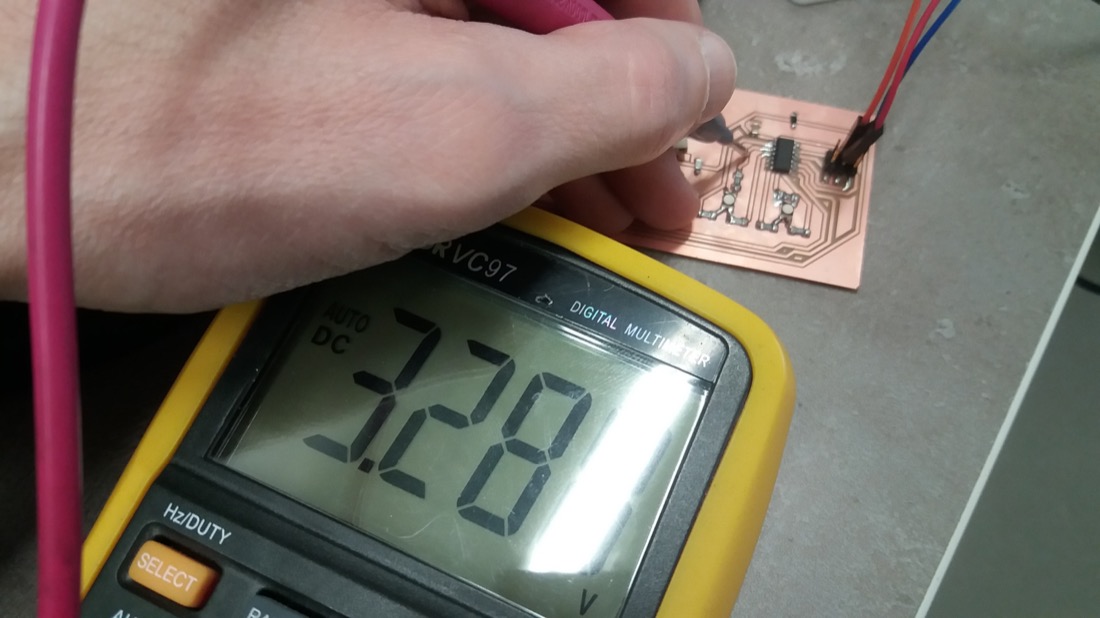
After many trials, I gave up on these RGB LEDs and desoldered them. I first thought that maybe the voltage wasn’t big enough, but according to their datasheet, it should be enough. I even tried with an external power supply to increase the voltage up to 5V but I didn’t have any result.
I soldered instead six LEDs of three different colors: green, red and blue and was able to see that the code worked indeed:
I2C communication
Since it seemed too complicated to work without the Arduino IDE environment, I switched back to it for the I2C communication part. Indeed, the “Wire” library would be very helpful!
I first had to add the ATTINY1614 board to the Arduino IDE. For this, I followed the instructions explained on this website. I had to add this line:
http://drazzy.com/package_drazzy.com_index.json
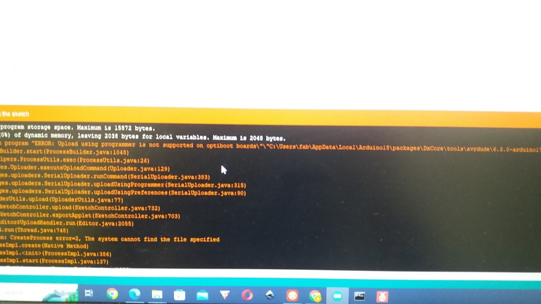
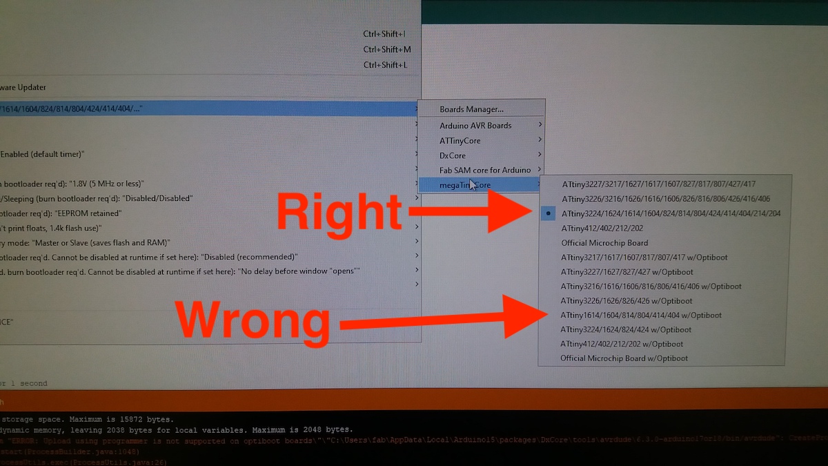
to the “Additional Boards Manager URLs” inside the Arduino IDE preferences. After installing the package for the ATTINY1614 (megaTinyCore from Spence Konde) from Tools -> Board -> Boards manager, I was able to select the ATTINY1614 as my board. However, in the beginning, I wasn’t able to upload the code because I was choosing the ATTINY1614 with Optiboot, which doesn’t support upload with UPDI:
Once I understood the cause, the fix was easy:
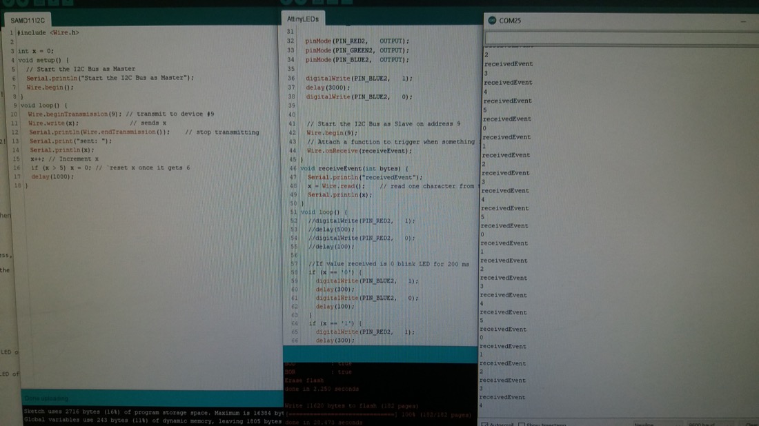
I could then start to write some basic code using the Wire.h library. I got some inspiration from this page.
SAMD11C as Primary:
#include <Wire.h>

int x = 0;
void setup() {
  // Start the I2C Bus as Primary
  Wire.begin();
}
void loop() {
  Wire.beginTransmission(9); // transmit to device #9
  Wire.write(x);              // sends x
  Serial.println(Wire.endTransmission());    // stop transmitting, write the function result to console
  Serial.print("sent: ");
  Serial.println(x);
  x++; // Increment x
  if (x > 5) x = 0; // reset x once it gets to 6
  delay(1000);
}
ATTINY1614 as Secondary:
#include <Wire.h>

int x = 0;
void setup() {
  // Start the I2C Bus as Secondary on address 9
  Wire.begin(9);
  // Attach a function to trigger when something is received.
  Wire.onReceive(receiveEvent);
}
void receiveEvent(int bytes) {
  x = Wire.read();    // read one byte from the I2C
  Serial.print("received: ");
  Serial.println(x);
}
void loop(){

}
I was surprised to see that this communication wasn’t working. I had done something similar during the Embedded Programming week and I didn’t have major problem… After searching for a while, I stumbled upon this page from Rodrigo Shordia, a former Fabacademy student. He explains the importance to have pullup resistors between the SDA and SCL pins and +5V. I didn’t think about it, because the Arduino has built in pullup resistors.
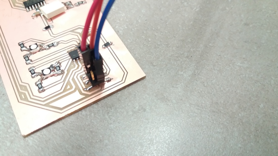
To calculate the appropriate resistance these pullup resistors should have can be a bit tricky. I saw that in the case of the Raspberry Pi, they put 1.8 kOhm resistors, so I decided to try an approximation of this value. Since I found 1kOhm resistors, I put 2 of these in series for each communication line (I also had to solder some pinheaders on SDA, SCL and 5V):
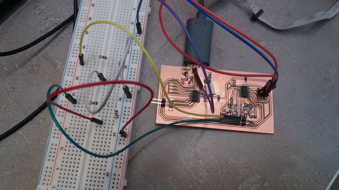
And that worked:
In order to make usage of the LEDs, I rewrote the Secondary on the ATTINY1614:
onst int PIN_GREEN = 0;
const int PIN_RED   = 1;
const int PIN_BLUE  = 2;

const int PIN_GREEN2 = 5;
const int PIN_RED2   = 4;
const int PIN_BLUE2  = 3;

#include <Wire.h>

int x = 0;
void setup() {
  pinMode(PIN_RED,   OUTPUT);
  pinMode(PIN_GREEN, OUTPUT);
  pinMode(PIN_BLUE,  OUTPUT);

  pinMode(PIN_RED2,   OUTPUT);
  pinMode(PIN_GREEN2, OUTPUT);
  pinMode(PIN_BLUE2,  OUTPUT);

  digitalWrite(PIN_BLUE2,   1);
  delay(3000);
  digitalWrite(PIN_BLUE2,   0);


  // Start the I2C Bus as Secondary on address 9
  Wire.begin(9);
  // Attach a function to trigger when something is received.
  Wire.onReceive(receiveEvent);
}
int receiveCounter = 0;
void receiveEvent(int bytes) {
  x = Wire.read();    // read one character from the I2C
}

void loop() {
  if (x == 0) {
    pinsDown();
    digitalWrite(PIN_BLUE2,   1);
  }
  if (x == 1) {
    pinsDown();
    digitalWrite(PIN_RED2,   1);
  }
  if (x == 2) {
    pinsDown();
    digitalWrite(PIN_GREEN2,   1);
  }
  if (x == 3) {
    pinsDown();
    digitalWrite(PIN_GREEN,   1);
  }
  if (x == 4) {
    pinsDown();
    digitalWrite(PIN_RED,   1);
  }
  if (x == 5) {
    pinsDown();
    digitalWrite(PIN_BLUE,   1);
  }
}

void pinsDown() {
  digitalWrite(PIN_RED,   0);
  digitalWrite(PIN_GREEN,   0);
  digitalWrite(PIN_BLUE,   0);
  digitalWrite(PIN_RED2,   0);
  digitalWrite(PIN_GREEN2,   0);
  digitalWrite(PIN_BLUE2,   0);
}
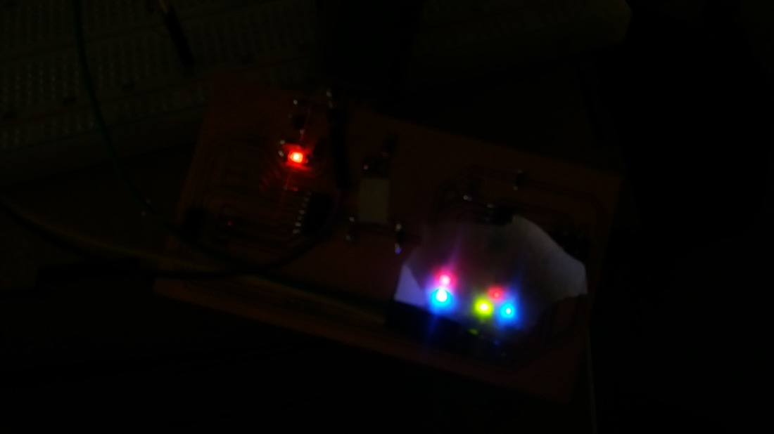
And this is the result:
Trying to read a message using OpenCV
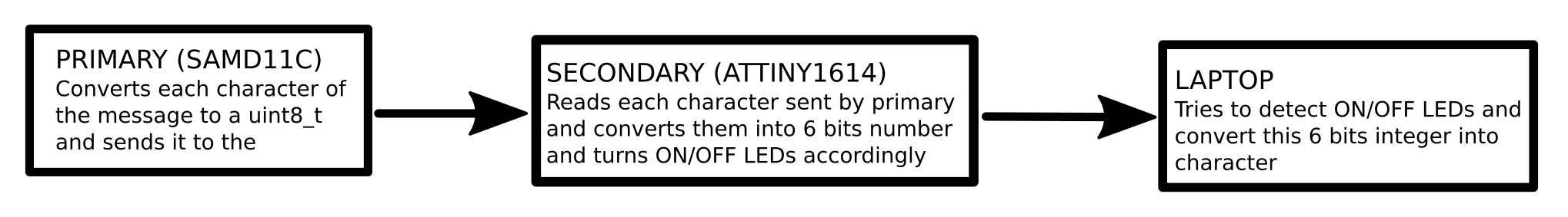
I wanted to take this project a bit further by sending characters from the Primary, reading them and converting them into 6 bits numbers, displaying these numbers using the LEDs and finally, using my laptop, reading the LEDs and converting them back into characters. Unfortunately, this last step was unsuccessful :-(.
The code for my Primary and Secondary were changed a bit.
Primary on SAMD11C:
#include <Wire.h>

char text[] = "HELLO_TEENY_TINY";     //I used underscore instead of SPACE because I need to fit the values of the characters into a 6 bits integer
uint8_t arrayIndex = 0;

void setup() {
  Wire.begin();
}

void loop() {
  uint8_t x = text[arrayIndex] - '@';     //in ASCII, the character '@' is just before 'A', which enables the alphabet to fit into a 6 bits integer (64 values)
  Wire.beginTransmission(9); // transmit to device #9
  Wire.write(x);              // sends x
  Serial.println(Wire.endTransmission());    // stop transmitting
  Serial.print("sent: ");
  Serial.print(x);
  Serial.print(" corresponding to ");
  Serial.println(text[arrayIndex]);
  arrayIndex++;
  if (arrayIndex > sizeof(text)) arrayIndex = 0;
  delay(1000);
}
Secondary on ATTINY1614:
const int PIN_GREEN = 0;
const int PIN_RED   = 1;
const int PIN_BLUE  = 2;

const int PIN_GREEN2 = 5;
const int PIN_RED2   = 4;
const int PIN_BLUE2  = 3;

#include <Wire.h>

int x = 0;
void setup() {
  pinMode(PIN_RED,   OUTPUT);
  pinMode(PIN_GREEN, OUTPUT);
  pinMode(PIN_BLUE,  OUTPUT);

  pinMode(PIN_RED2,   OUTPUT);
  pinMode(PIN_GREEN2, OUTPUT);
  pinMode(PIN_BLUE2,  OUTPUT);

  digitalWrite(PIN_BLUE2,   1);
  delay(3000);
  digitalWrite(PIN_BLUE2,   0);


  Wire.begin(9);
  Wire.onReceive(receiveEvent);
}
int receiveCounter = 0;
void receiveEvent(int bytes) {
  x = Wire.read();    // read one byte from the I2C
}

void loop() {
  pinsDown();

  //decimal to 6 bits binary number

  int fiveBits = x % 32;
  int bitSix = x / 32;
  if (bitSix == 1) digitalWrite(PIN_GREEN,   1);

  int fourBits = fiveBits % 16;
  int bitFive = fiveBits / 16;
  if (bitFive == 1) digitalWrite(PIN_RED,   1);

  int threeBits = fourBits % 8;
  int bitFour = fourBits / 8;
  if (bitFour == 1) digitalWrite(PIN_BLUE,   1);

  int twoBits = threeBits % 4;
  int bitThree = threeBits / 4;
  if (bitThree == 1) digitalWrite(PIN_GREEN2,   1);

  int oneBits = twoBits % 2;
  int bitTwo = twoBits / 2;
  if (bitTwo == 1) digitalWrite(PIN_RED2,   1);

  if (oneBits == 1) digitalWrite(PIN_BLUE2,   1);
}

void pinsDown() {
  digitalWrite(PIN_RED,   0);
  digitalWrite(PIN_GREEN,   0);
  digitalWrite(PIN_BLUE,   0);
  digitalWrite(PIN_RED2,   0);
  digitalWrite(PIN_GREEN2,   0);
  digitalWrite(PIN_BLUE2,   0);
}
The python code using OpenCV to detect which LEDs were on was a harder for me. I had toyed around with OpenCV a few times, but I never really wrote myself any code for computer vision. The two main resources I used to write the code were this documentation on how to mask some color in an image and stackoverflow answer for counting colored objects. I then tried to detect the LEDs using this code:
import cv2
import numpy as np
import time
from collections import Counter

decimalLetter = 0
lastValuesArray = [0,0,0,0,0,0,0,0,0,0]

def drawContoursForColor(mask, colorName):
    global decimalLetter
    # Find the contours on the binary image:
    contours, hierarchy = cv2.findContours(mask, cv2.RETR_EXTERNAL, cv2.CHAIN_APPROX_SIMPLE)

    # Store bounding rectangles and object id here:
    objectData = []

    # ObjectCounter:
    objectCounter = 1

    height, width = mask.shape[:2]

    # Look for the outer bounding boxes (no children):
    for _, c in enumerate(contours):
        # Get the contour's bounding rectangle:
        boundRect = cv2.boundingRect(c)

        #Count an object only if it is within certain limits of the image
        if boundRect[2] > 10 and boundRect[3] > 10 and boundRect[0] > width * 0.7 and  boundRect[0] < width * 0.9 and boundRect[1] > height * 0.7 and boundRect[1] < height * 0.85:
            # Store in list:
            objectData.append((objectCounter, boundRect))

            # Get the dimensions of the bounding rect:
            rectX = boundRect[0]
            rectY = boundRect[1]
            rectWidth = boundRect[2]
            rectHeight = boundRect[3]

            #Decode the character:
            if colorName == "blue" :
                if boundRect[0] > width * 0.7 and  boundRect[0] < width * 0.8 :
                    decimalLetter += 8
                else:
                    decimalLetter += 1
            elif colorName == "red" :
                if boundRect[0] > width * 0.7 and  boundRect[0] < width * 0.8 :
                    decimalLetter += 16
                else:
                    decimalLetter += 2
            else:
                if boundRect[0] > width * 0.7 and  boundRect[0] < width * 0.8 :
                    decimalLetter += 32
                else:
                    decimalLetter += 4

            # Draw bounding rect:
            color = (0, 0, 255)
            cv2.rectangle(inputImageCopy, (int(rectX), int(rectY)),
                          (int(rectX + rectWidth), int(rectY + rectHeight)), color, 2)

            # Draw object counter:
            font = cv2.FONT_HERSHEY_SIMPLEX
            fontScale = 1
            fontThickness = 2
            color = (0, 255, 0)
            cv2.putText(inputImageCopy, str(colorName) + " " + str(objectCounter), (int(rectX), int(rectY)),
                        font, fontScale, color, fontThickness)

            # Increment object counter
            objectCounter += 1


#begin video capture
cap = cv2.VideoCapture(0)
while(1):
    # Take each frame
    _, inputImage = cap.read()

    hsv = cv2.cvtColor(inputImage, cv2.COLOR_BGR2HSV)
    lower_range = np.array([155,70,70])
    upper_range = np.array([175,255,255])
    maskRed = cv2.inRange(hsv, lower_range, upper_range)
    lower_range = np.array([20,70,70])
    upper_range = np.array([40,220,220])
    maskGreen = cv2.inRange(hsv, lower_range, upper_range)
    lower_range = np.array([80,70,70])
    upper_range = np.array([100,255,255])
    maskBlue = cv2.inRange(hsv, lower_range, upper_range)

    # Deep copy for results:
    inputImageCopy = inputImage.copy()

    drawContoursForColor(maskRed, "red")
    drawContoursForColor(maskGreen, "green")
    drawContoursForColor(maskBlue, "blue")

    height, width = inputImageCopy.shape[:2]
    cv2.rectangle(inputImageCopy, (int(width * 0.7), int(height*0.7)), (int(width * 0.8), int(height*0.85)), (0,0,255), 2)
    cv2.rectangle(inputImageCopy, (int(width * 0.8), int(height*0.7)), (int(width * 0.9), int(height * 0.85)), (255,0,0), 2)


    cv2.imshow("Rectangles", inputImageCopy)

    #use lastValuesArray to average the values and attempt to filter out noise
    lastValuesArray.append(decimalLetter)
    lastValuesArray.pop(0)

    c = Counter(lastValuesArray)
    decLetter = c.most_common(1)[0][0]
    #take the character into account only if it was detected at least 6 times in the last 10 frames
    if c.most_common(1)[0][1] > 5 and decLetter != 0:
        print(decLetter , " / " , chr(decLetter + 64))
        lastValuesArray = [0,0,0,0,0,0,0,0,0,0]

    time.sleep(0.1)
    decimalLetter = 0

    #cv2.waitKey(0)
    k = cv2.waitKey(5) & 0xFF
    if k == 27:
        break
cv2.destroyAllWindows()
As I said above, the detection wasn’t successful. One of the problems I encountered was that my builtin webcam wasn’t very good. The brightness adjustement made it very difficult to obtain consistent colors. One fix was to cover the LEDs with some scotch tape to make them less bright:
I also tried to shine some flashlight into the webcam next to my LEDs to prevent them to appear too bright on the image. Even with these fixes, the number of errors was much too high.
Sometimes, the character was read correctly:
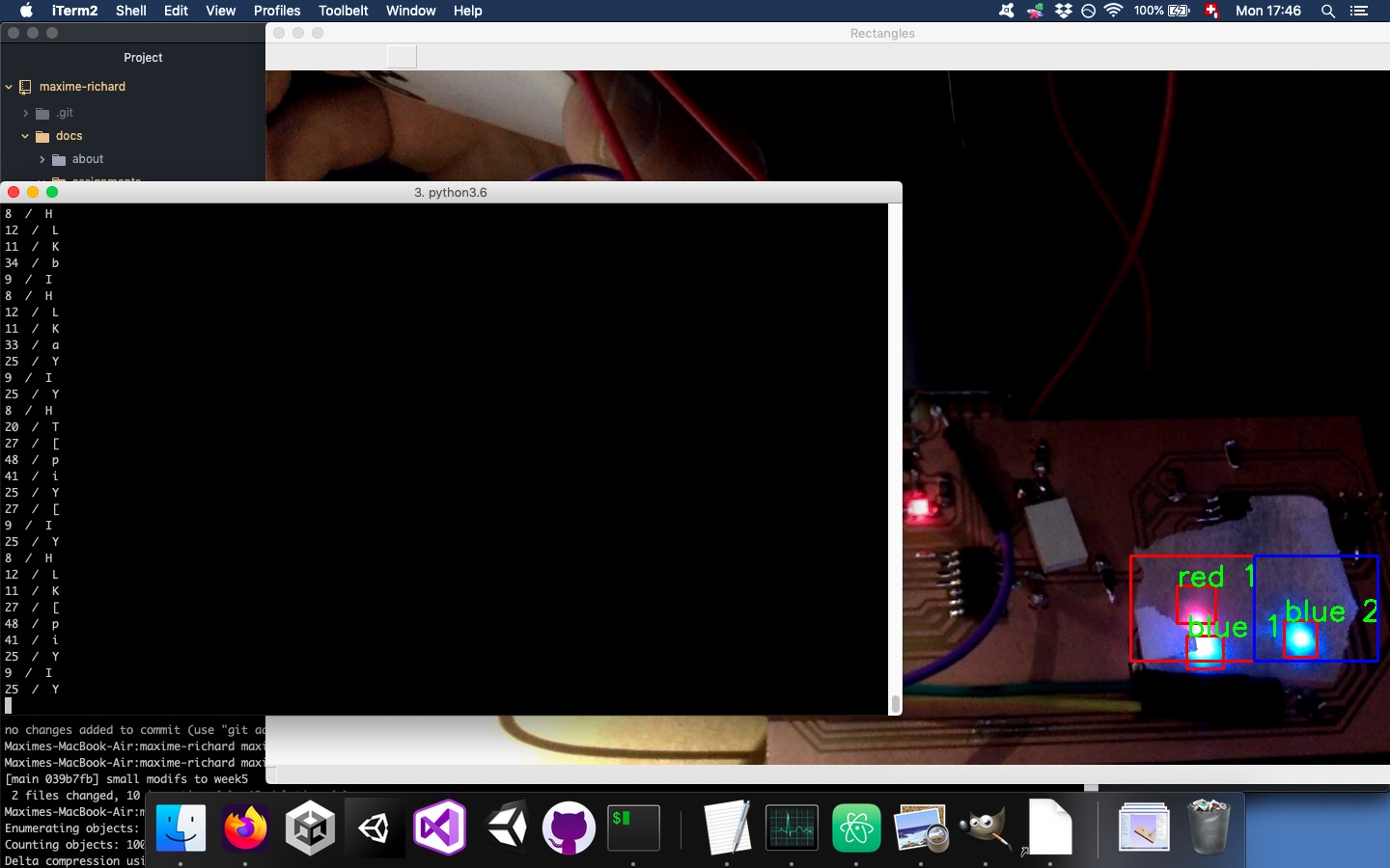
But it was often wrong:
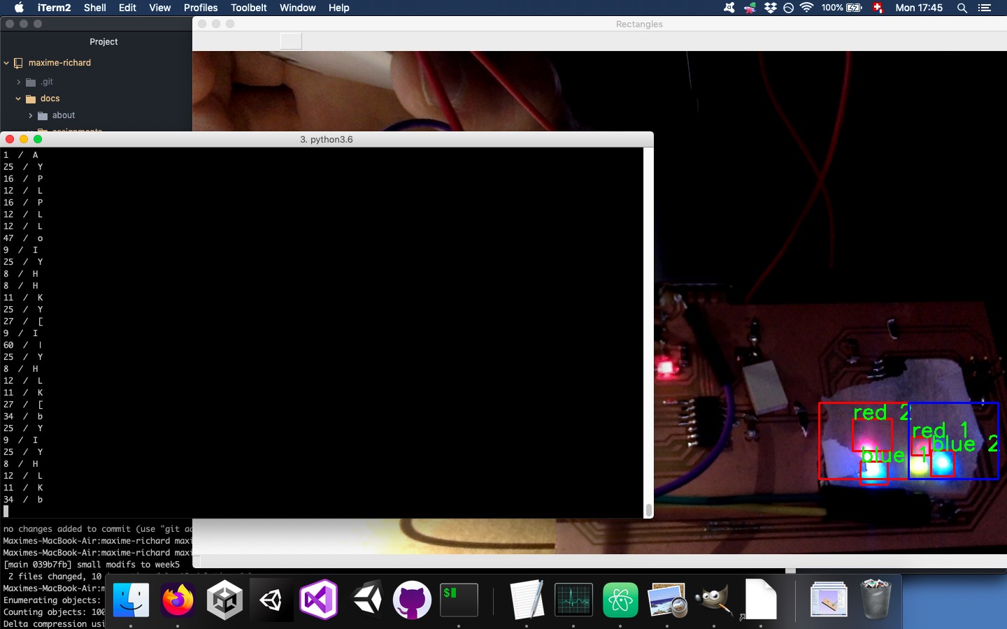
This is one of the best sequences I had:
It read “HELLO_DEELY_DILY” instead of “HELLO_TEENY_TINY”. So it consistently misread ‘D’ instead of ‘T’ and ‘L’ instead of ‘N’.
We can understand this for the T:
| Character | Decimal number | Binary number | LEDs | |
|---|---|---|---|---|
| Truth | T | 20 | 10100 | - R - G - - |
| Read | D | 4 | 100 | - - - G - - |
And for the N:
| Character | Decimal number | Binary number | LEDs | |
|---|---|---|---|---|
| Truth | N | 14 | 1110 | - - B G R - |
| Read | L | 12 | 1100 | - - B G - - |
In both cases, it was missing a red LED, which makes sense since it was the less bright one.
Group assignment
This week, we did the group assignment at the end of the week. We could use our own projects for networking. We used the I2C protocol for the communication. We had to implelement pull up resistors between Vcc and the SDA and SCL pins on a breadboard, since we didn’t have them on our PCBs. If we would use some Arduino, the pull up resistor would be already activated and we wouldn’t need any other resistor.
The I2C protocol works with two wires. The SCL wire is the “clock” which gives the rythm of the communication. It goes HIGH and LOW at a specific frequency, and a bit is transmitted at every cycle (when it is HIGH). Data transfers are initiated and interrupted by Start and Stop conditions: the Start condition happens when SDA is being pulled down while SCL is HIGH and the Stop condition is when SCL is pulled up, followed by SDA being pulled up:
![]()
I2C follows the Primary/Secondaries model. There is only one Primary but there can be multiple Secondaries. Communication is initiated by the Primary. The Secondaries are identified by addresses which can be 7-bit or 10-bit long. In our case, we had only three devices, one Primary and two Secondaries.
Conclusion
This week started well, since I could easily program my gamepad using informations provided during the lecture.
One of the big learning outcomes of this week was the usage of the ATTINY1614 workflow. I faced few difficulties but I could eventually overcome them. An other important take away from this week was the importance of pullup resistor when using the I2C protocol.
The main failure of this week was that I couldn’t reliably read the LEDs colors using the camera and OpenCV. It is technically probably not that hard to overcome this obstacle, but my skills in computer vision are unfortunately not good enough.
Files
code for the secondary ATTINY1614
python code for the LEDs recognition