Final Project: documenting the process
WARNING: This page contains videos with flashing lights
Since I came up quite late with the idea for this final project, not many weeks are related to it. Only the one about applications and implications and the one about invention, intellectual property and income are.
Concept
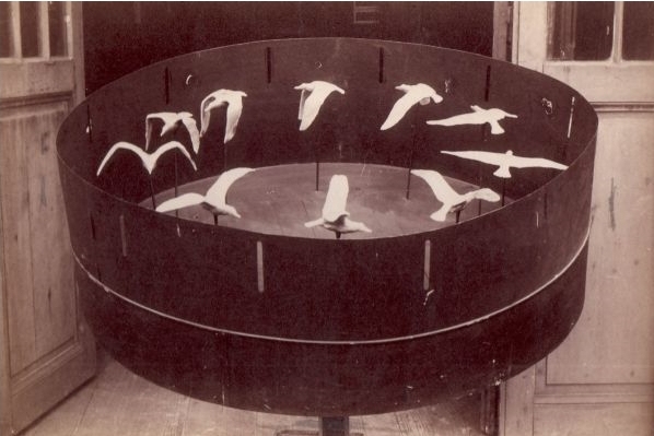
For my final project, I want to make a zeotrope. This kind of devices use the persistence of vision and the phi phenomenon to animate still images placed on a rotating disc. These images can be seen, for example, through narrow slits:
My goal is to make some simple animation of 3D printed solids using the stroboscopic effect created by flashing LEDs.
During my research, I found few former Fabacademy students who made zoetropes: Juliana Henno and Alex Garcia made a 3D zoetrope that animates a deforming cube. Faisal Al Kilani animated a 3D sculpture based on a Fibonacci sequence and adjusted the rotation speed using Hall effect sensors and PID controlling.
Mat Collishaw made some large 3D printed animated sculptures that look really beautiful.
Akinoro Goto made an incredible animation of a ballet dancer. This one since to use a slightly different technique that doesn’t use a stroboscopic effect, but continuously animates a 2D shape inside a 3D print using a narrow beam of light.
Spiral development
-
Make all the different parts of the system work: DC motor turning the zeotrope, sensor giving data to the MCU and LEDs flashing.
-
The next one will be to be able to see a smooth motion with the eyes, and then the camera.
-
Esthetics of the zoetrope.
Animation tests
To have a better idea of the final render, I did a first animation render in Blender with a placeholder:
In order to block the animation, I needed to conduct few tests. The first one was this:
Blender
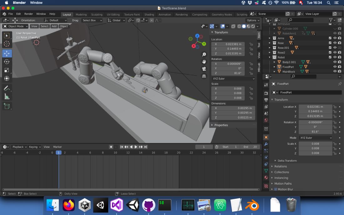
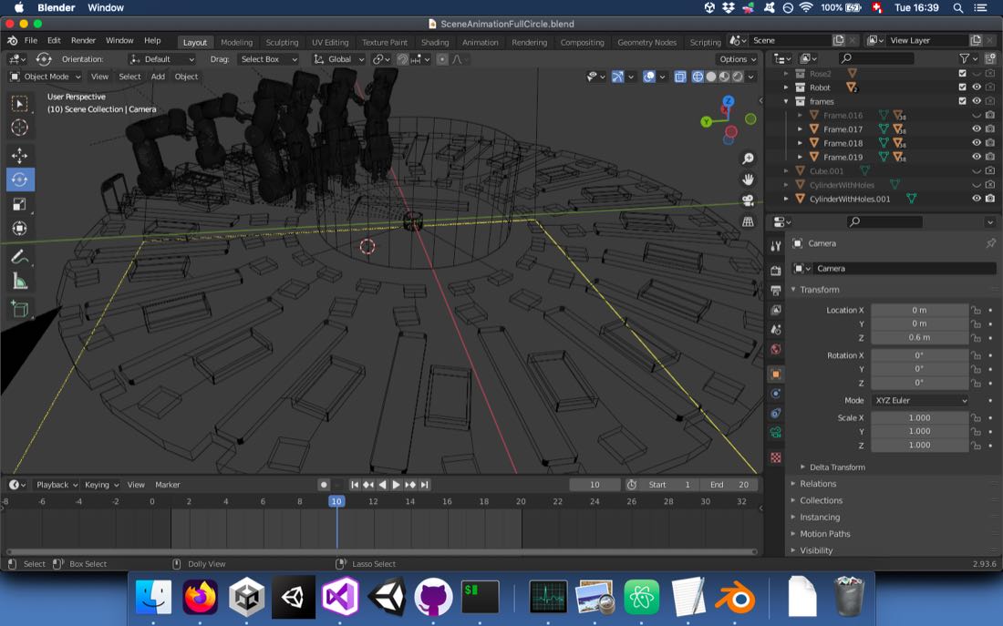
In order to design my scene, I used Blender. Since I needed to simulate some animation, it was the best choice for me.
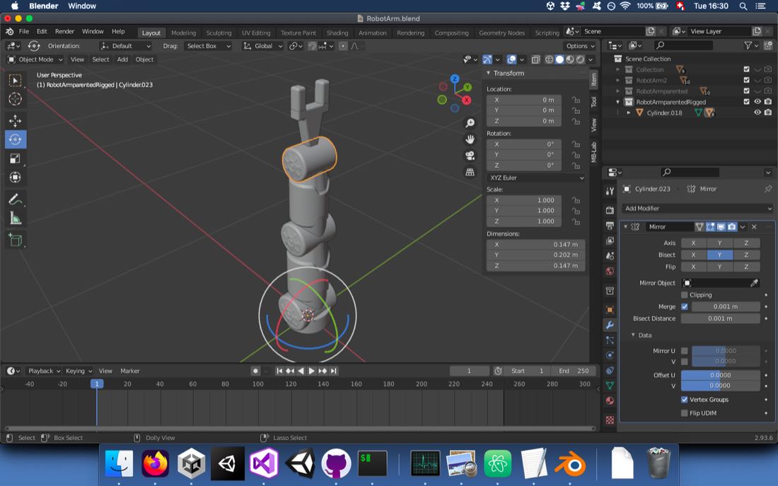
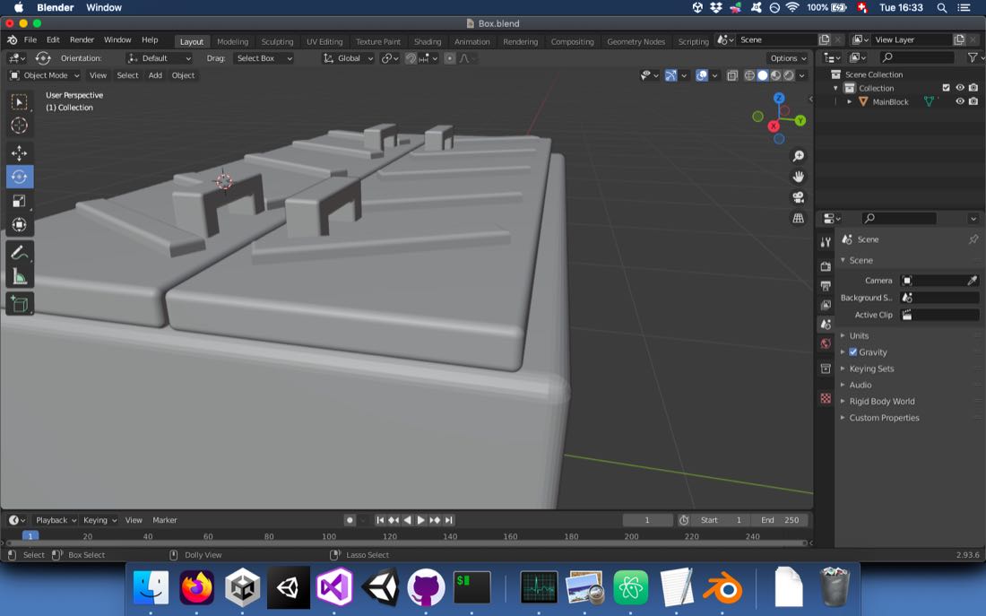
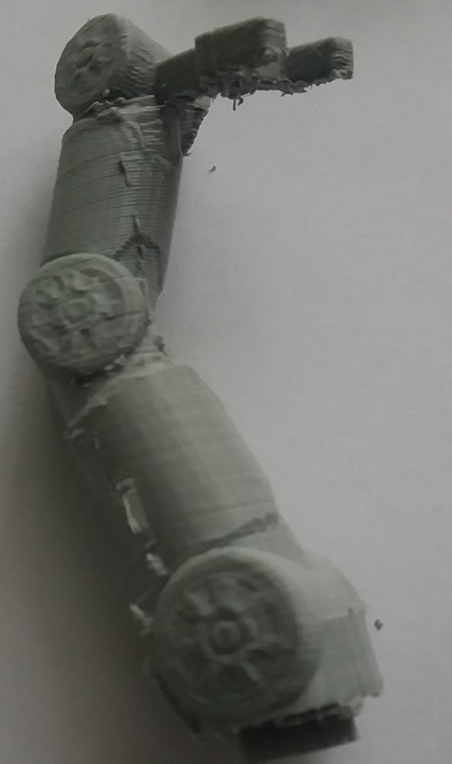
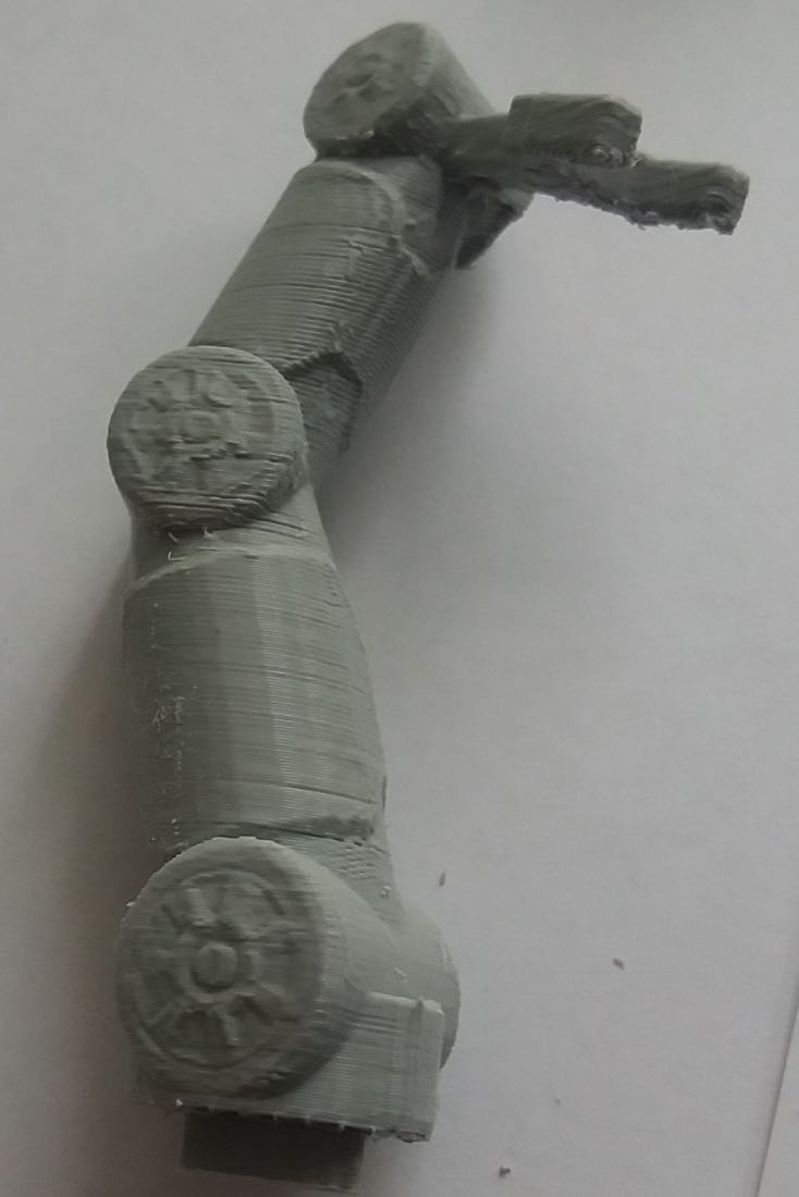
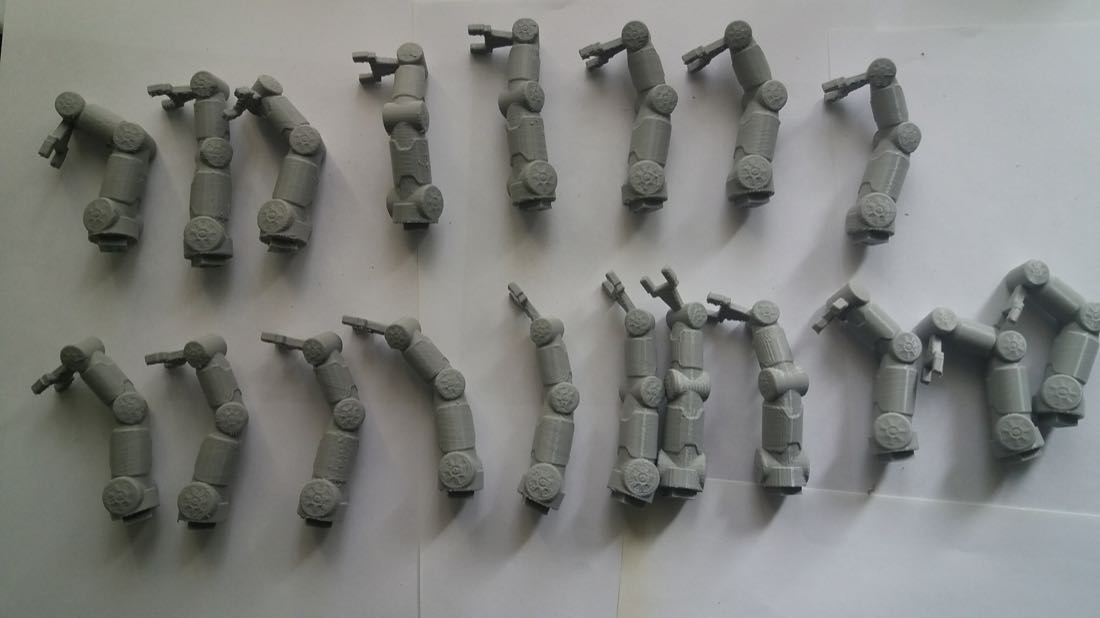
I started by making the robotic arm. The articulation was made by setting the hierarchy so that each part has its parent lower in the arm. After placing the pivot at the center of the parent, each part of the arm can be articulated by rotating the parent.
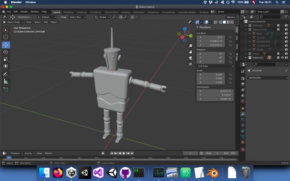
Then, I modeled a robot. I used the same technique for articulating it.
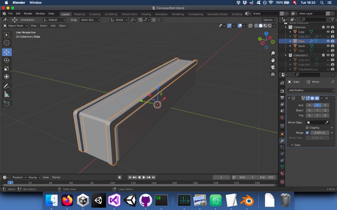
I also modeled some kind of conveyor belt:
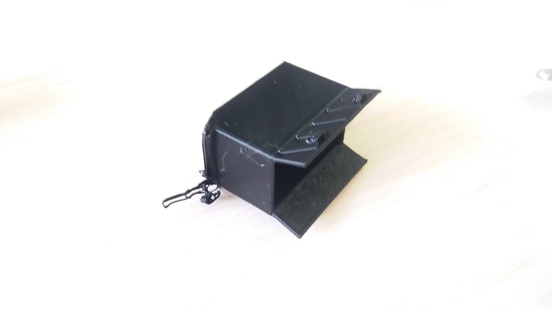
And eventually a box that could open and close:
Once all the different components were modeled, I tried to design the scene:
3D printing
For printing my models, I used four different 3D printers. I used the MakerBot slicer for the two MakerBot printers.
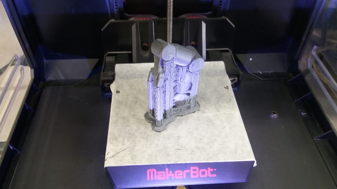
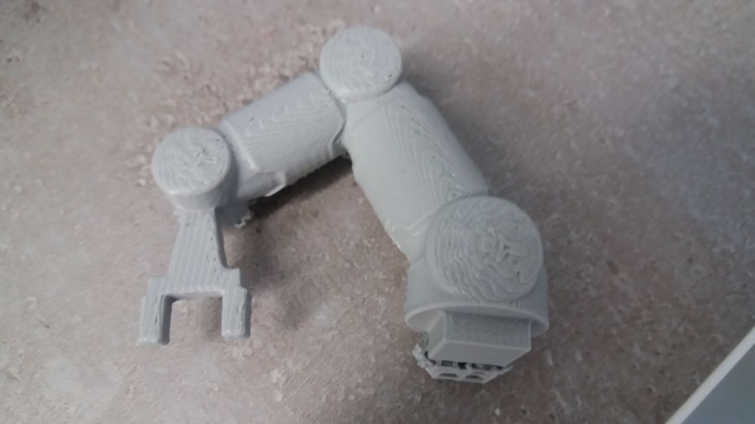
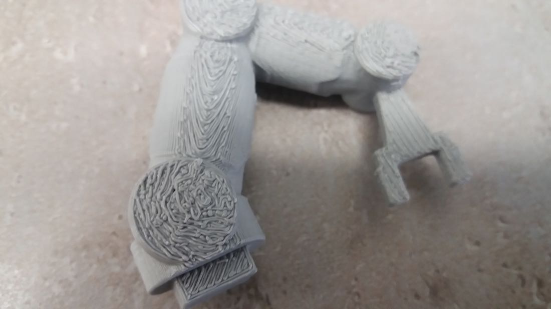
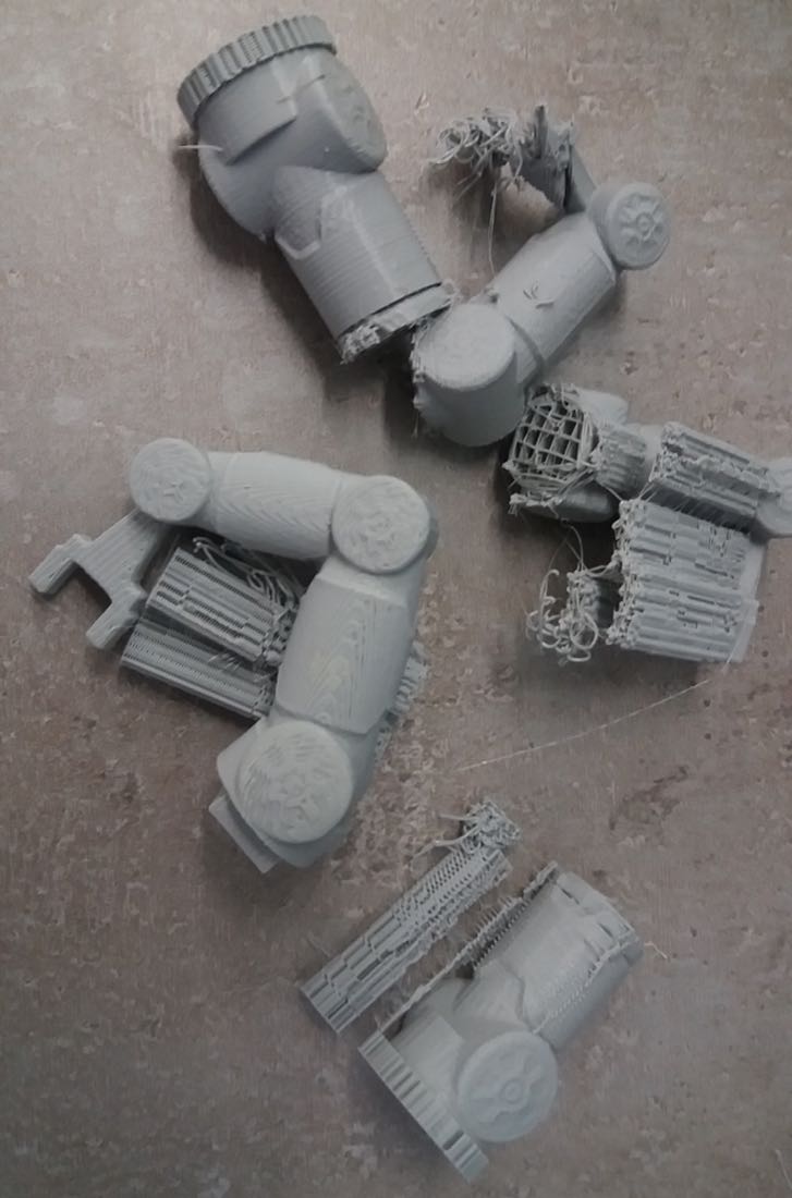
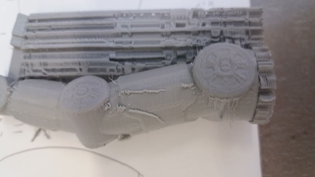
At the beginning, I tried to print the robotic arm laying instead of standing. However, the result wasn’t good:
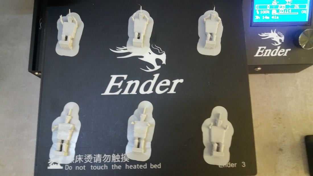
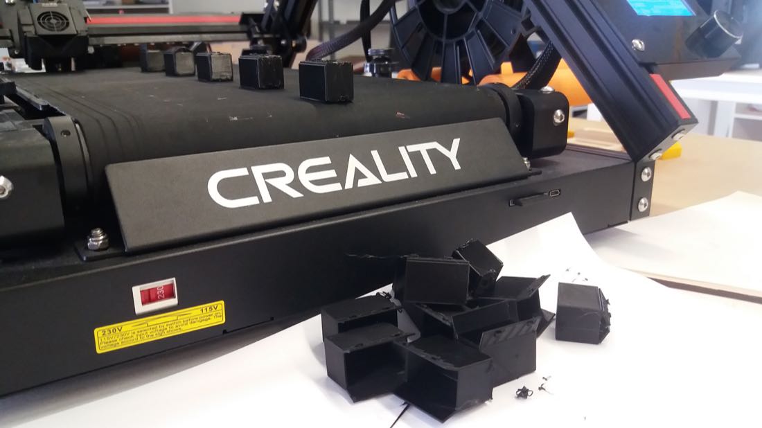
For the Creality Ender 3, I used the Cura Slicer. Since I had many models to print, it was very useful to be able to print several models in one job. However, printing different models at the same time often results in some failure. Therefore, I used an option present in Cura (Print Sequence) that enables to print a whole model before starting an other one. This yields much better results.
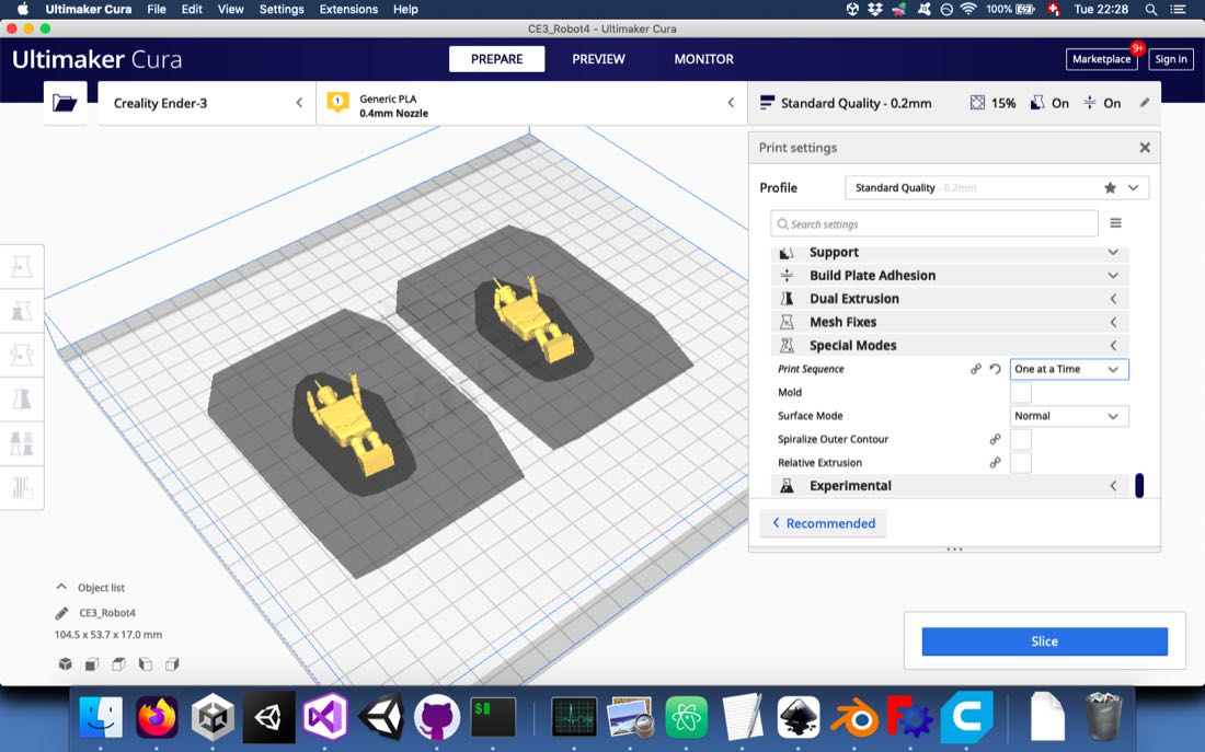
The downside of this method is that the printed model cannot be too high, otherwise it would be knocked down by the printer axis. It was possible to lay the robot on its back so that it would be low enough.
For the Creality CR30, I used the slicer SainSmart.
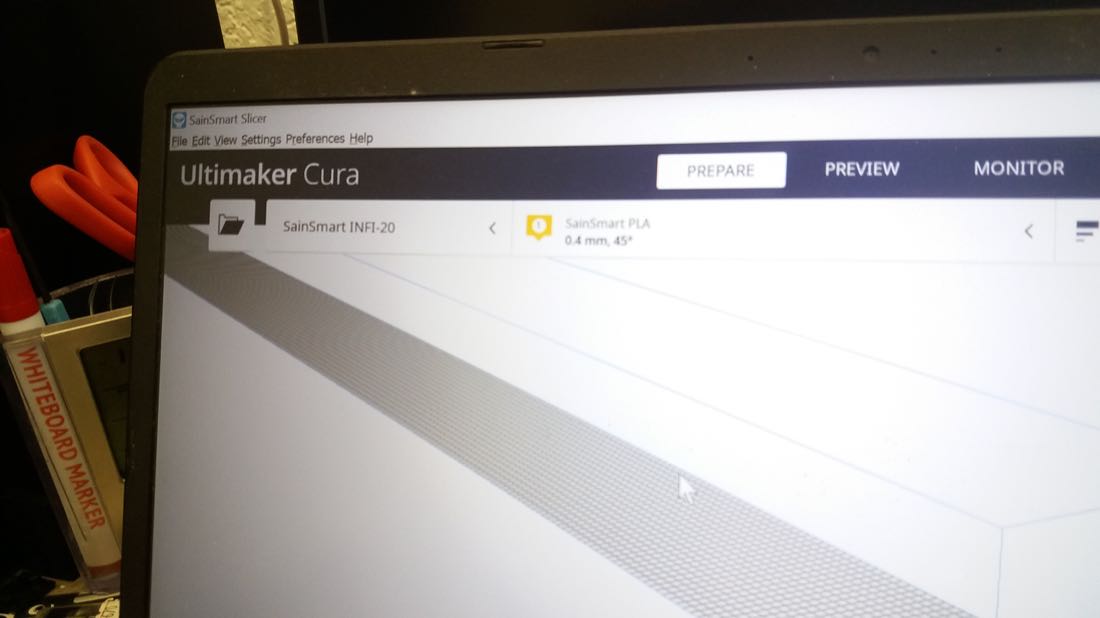
The big advantage of this printer was that I could print as many parts as I wanted in one job. So I could print overnight.
One disadvantage was that the beginning of each piece was a bit sloppy
I also had some failure at the beginning. I launched a job overnight with many pieces. The second piece didn’t print correctly. Fortunately, Rudolf saw it and tightened the belt. The rest of the job printed correctly:
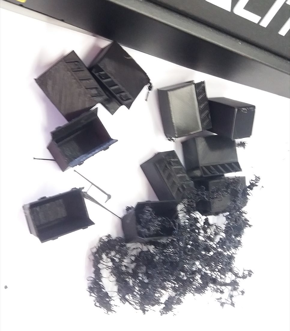
At the start, I had many failures.
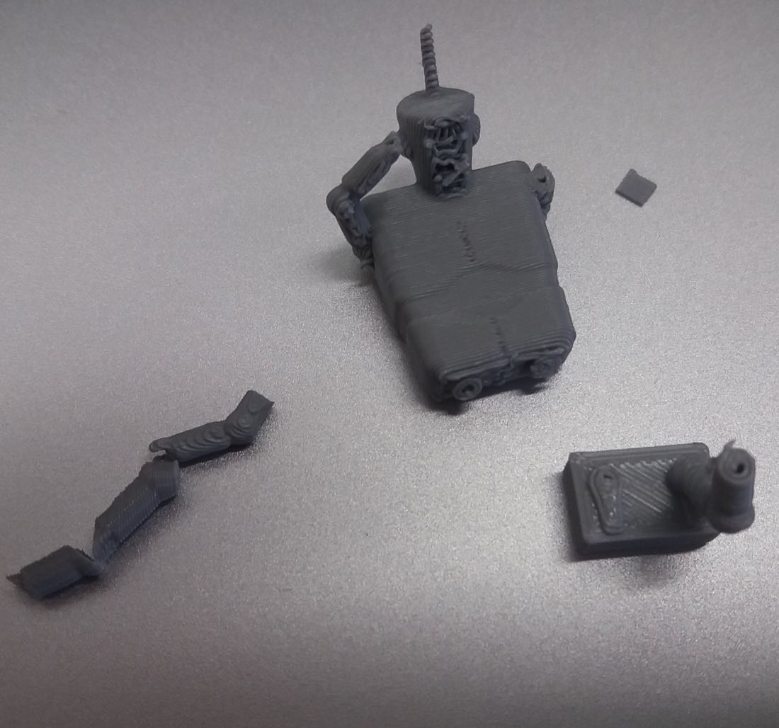
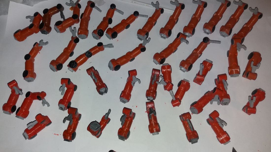
Just after printing, a lot of post processing was still needed.
CAD design
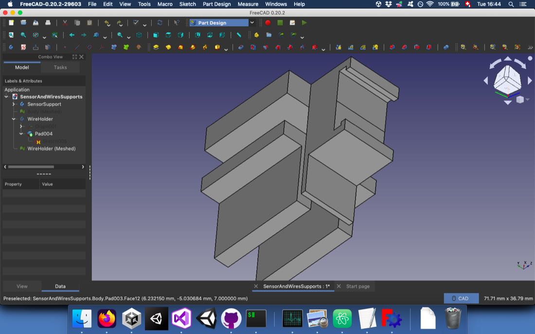
For the frame of the zoetrope, I used FreeCAD and Inkscape for the design. I designed most of the parts inside one file in order to better understand how they articulate.
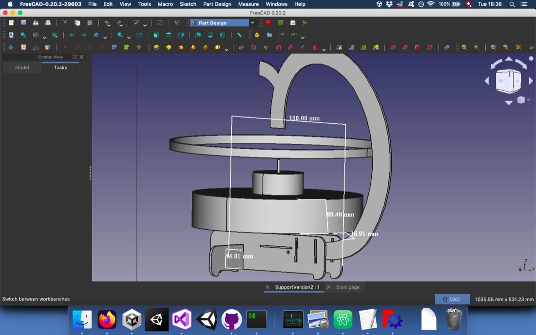
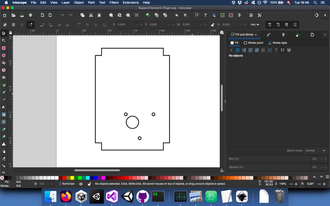
Later, I noticed that I need a small part to maintain the hall effect sensor in place close to the rotating magnets. I quickly designed it in FreeCAD:
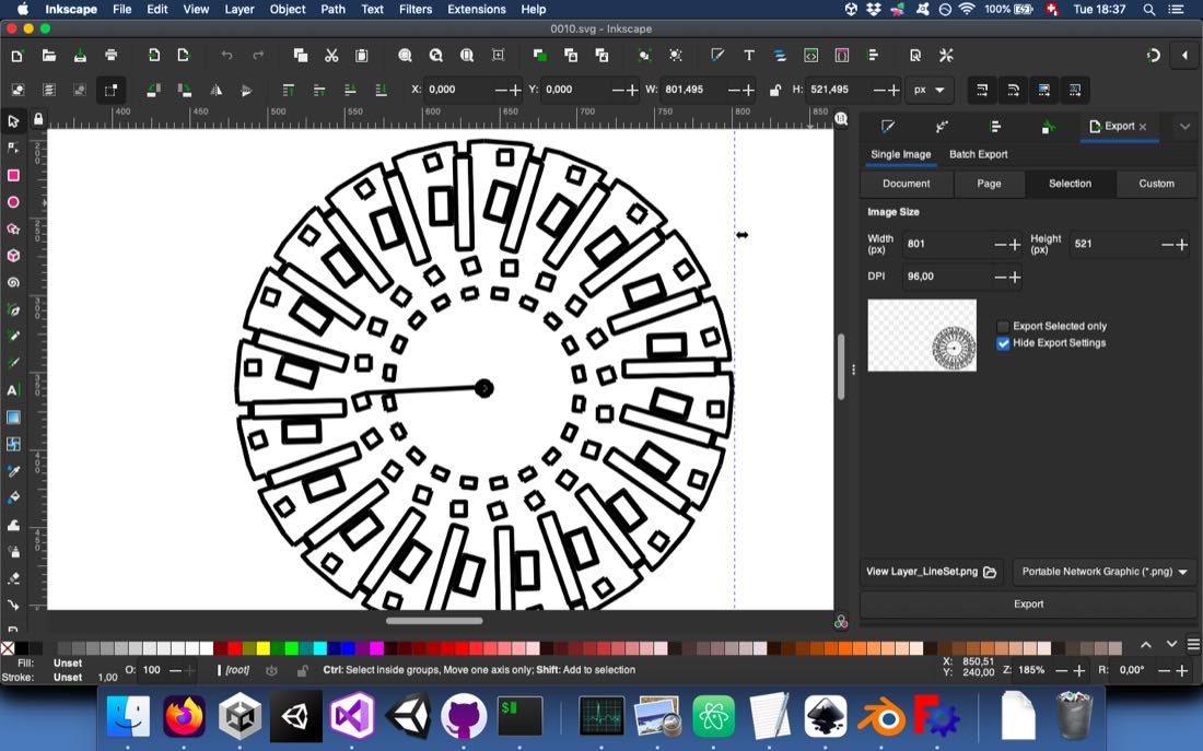
Once my designs were ready, I needed to prepare them for CNC machining. First, I made the disk that would hold the scene. Since all 3D printed parts have some joint that will be inserted inside the disk, I made these pockets inside Blender using the boolean modifier:
For CNC machining, I needed to have a .svg file. If it’s quite easy from FreeCAD to export a 2D projection using the TechDraw workbench, I didn’t know how to do it from Blender. Fortunately, there is a rendering option that enables this. After setting the camera in orthographic mode and putting it above the disk at 90°, I went to the Render Properties tab and chose the Freestyle SVG Export option.
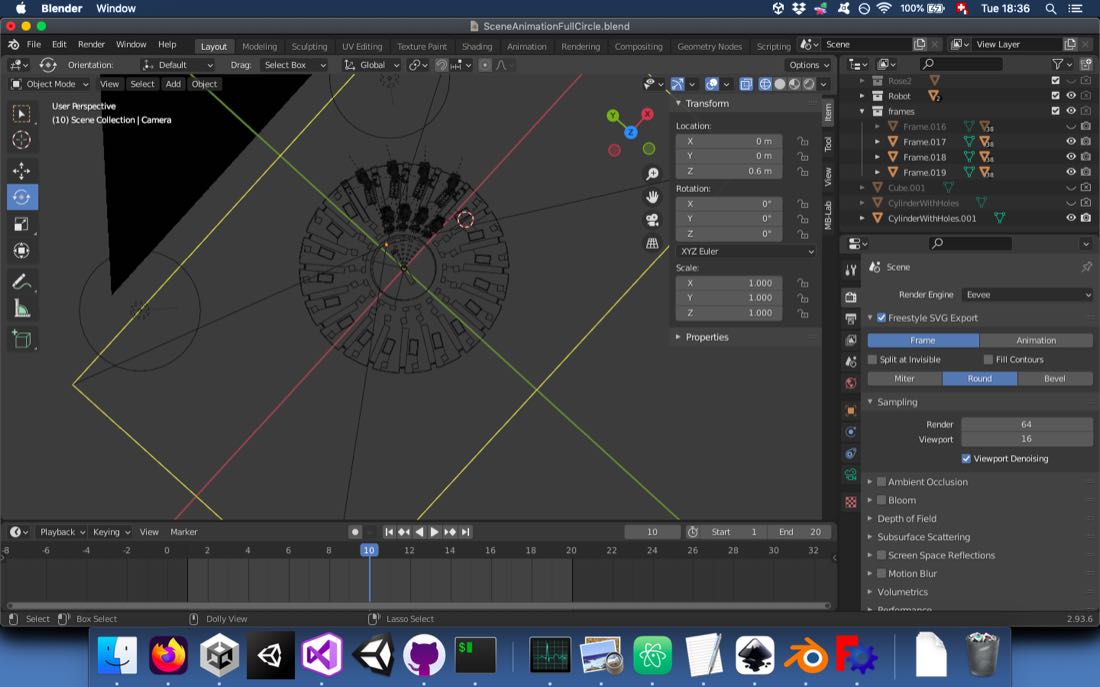
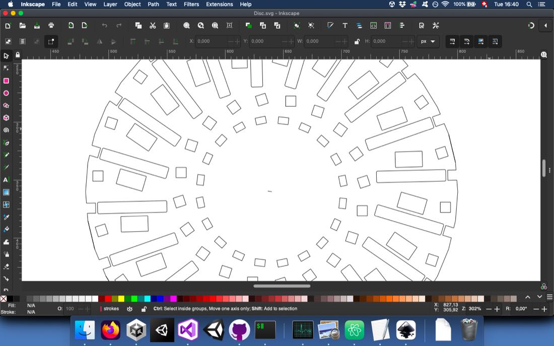
I obtained a file that still needed a lot of clean up, but it was good enough for my purpose:
After some work I could get a file ready for exporting for VCarve Pro.
For the frame designed in FreeCAD, the export to a .svg file was easier.
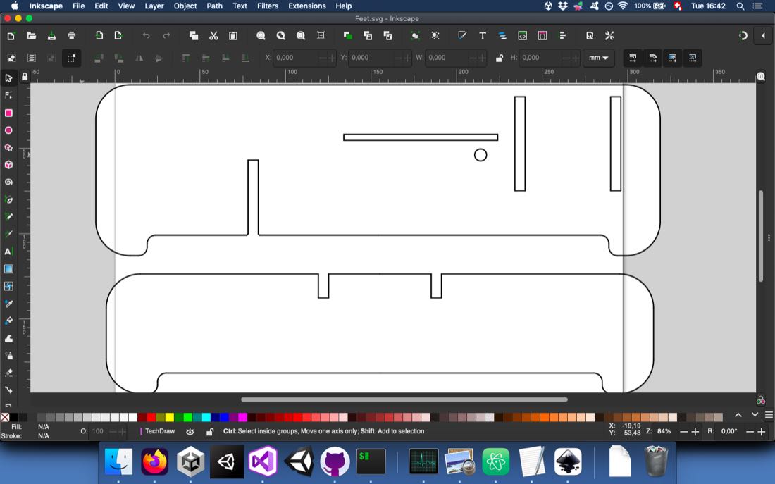
The same way, I exported the file that would serve for laser cutting:
Computer controlled machining
2D machining
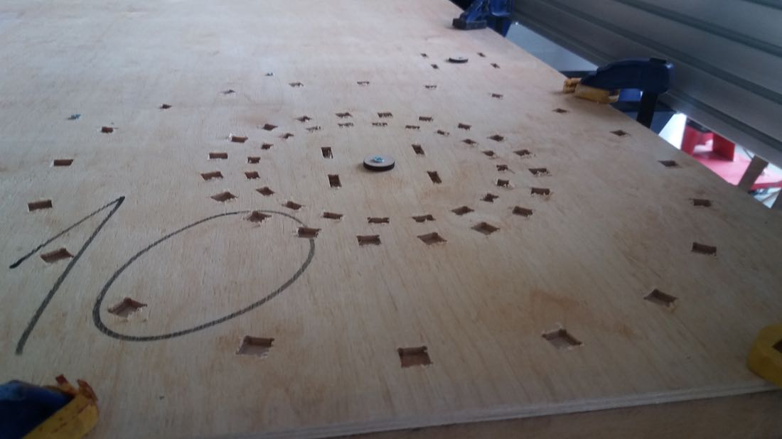
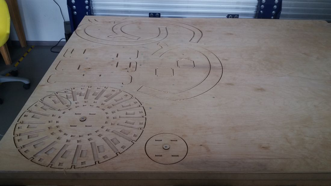
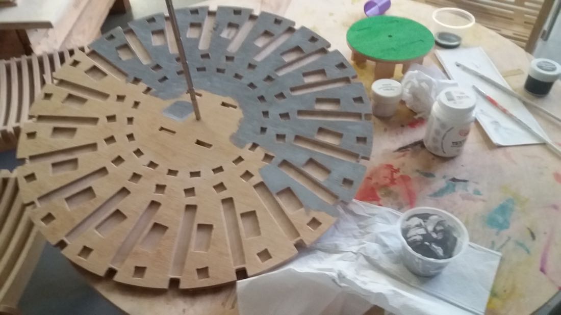
Once my files were ready, I started to cut with the CNC.
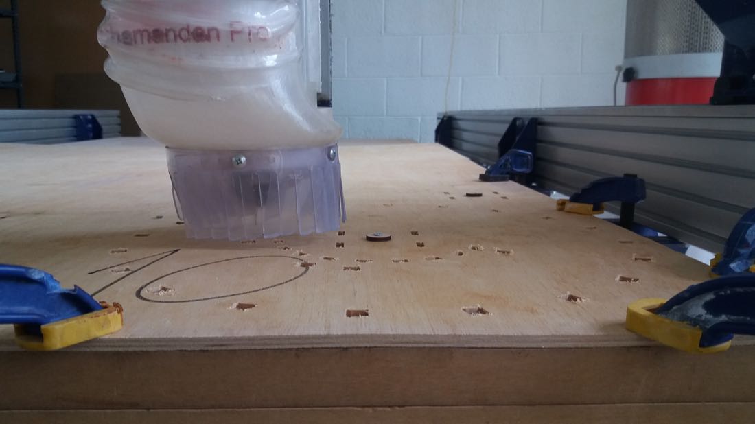
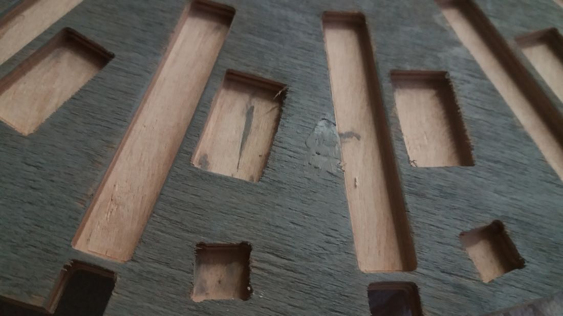
First, I pocketed the disk. I was careful to secure the plank to the MDF sacrificial bed with screws. As I was cutting, I was also testing the pocket size with my parts. Since some of the 3D printers are not very accurate and print a bit larger, I had to enlarge the pockets several times.
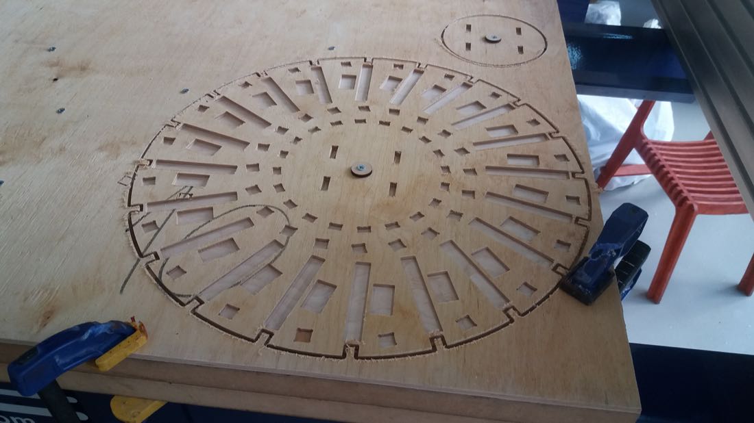
I had a weird situtation when cutting: I paused the job at some point, and after relaunching it, it continued on a very different path. I thought that it may have lost the X/Y zero, but after checking, this was still accurate. I relaunched the job from the start and it was perfectly aligned… I don’t know what happened.
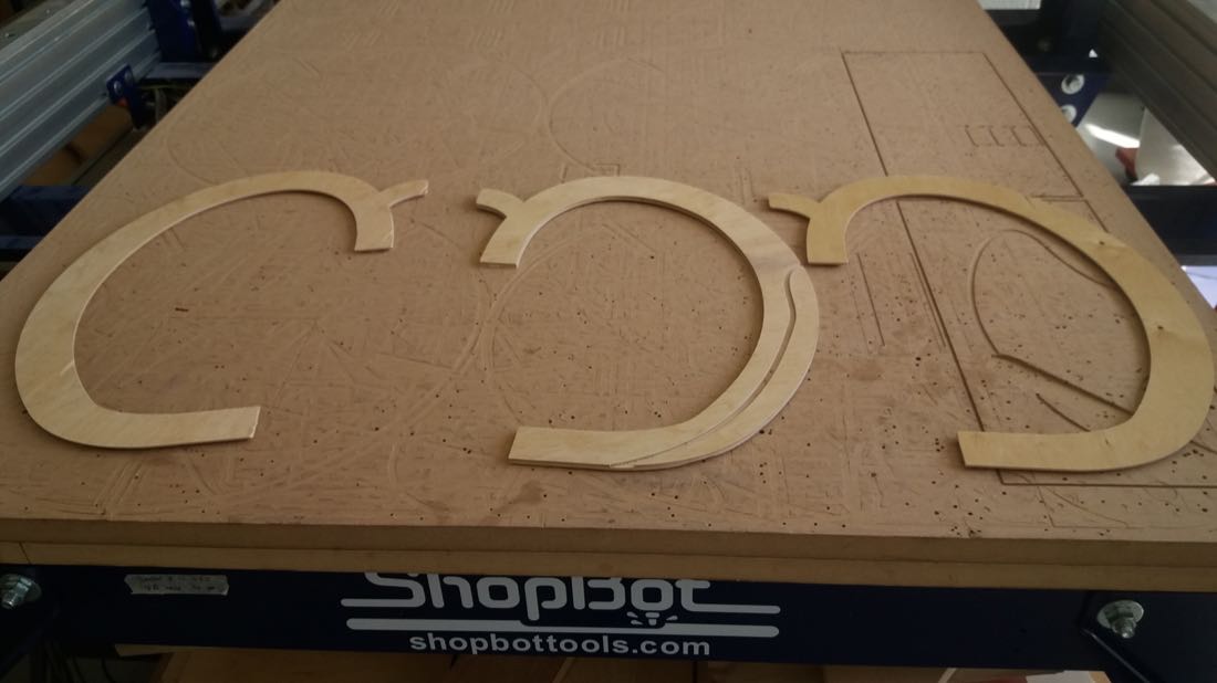
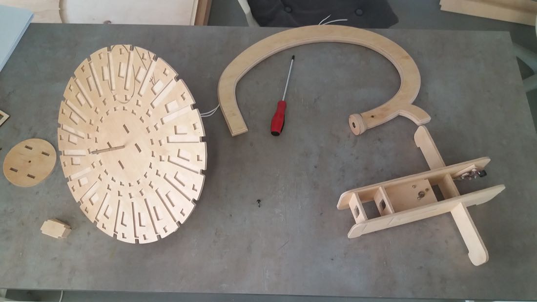
After a lot of efforts, I finally cut the main disk:
The parts for the frame were more straight forward to machine:
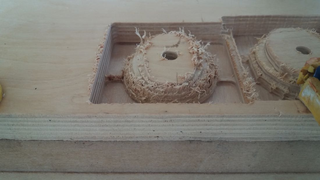
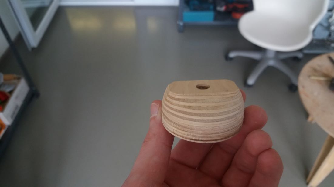
3D milling
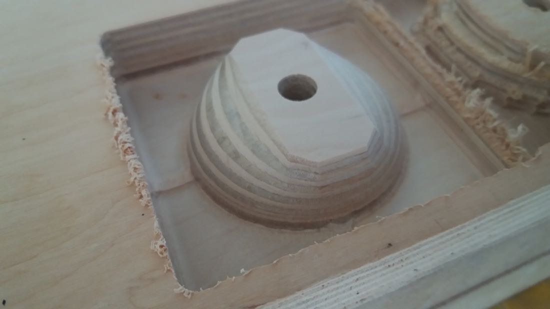
I also had to 3D mill a small part. I first did a rough cut.
And after the finish cut, the result was like this:
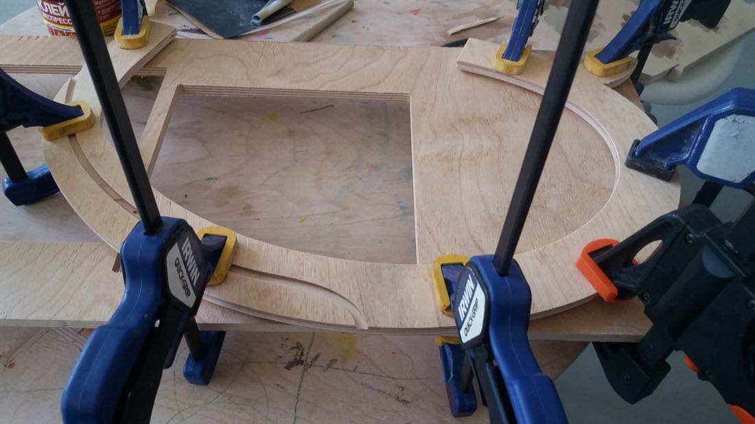
I also cut a small disk with a hole in the middle that would have to be glued to it:
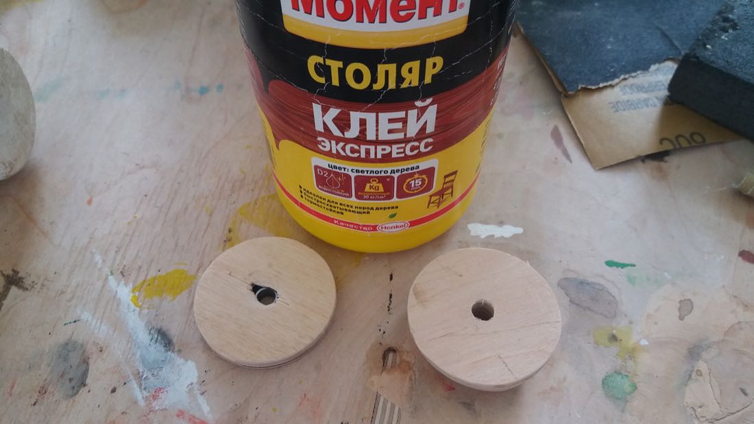
After waiting for the glue to solidify, I obtained this piece:
Making the board
For my project, I needed a hall effect sensor. We had the A1324 in stock, so I took this one. I also needed a DC motor and chose to control it with the A4953 driver. For the LEDs strip, I would control them with a transistor.
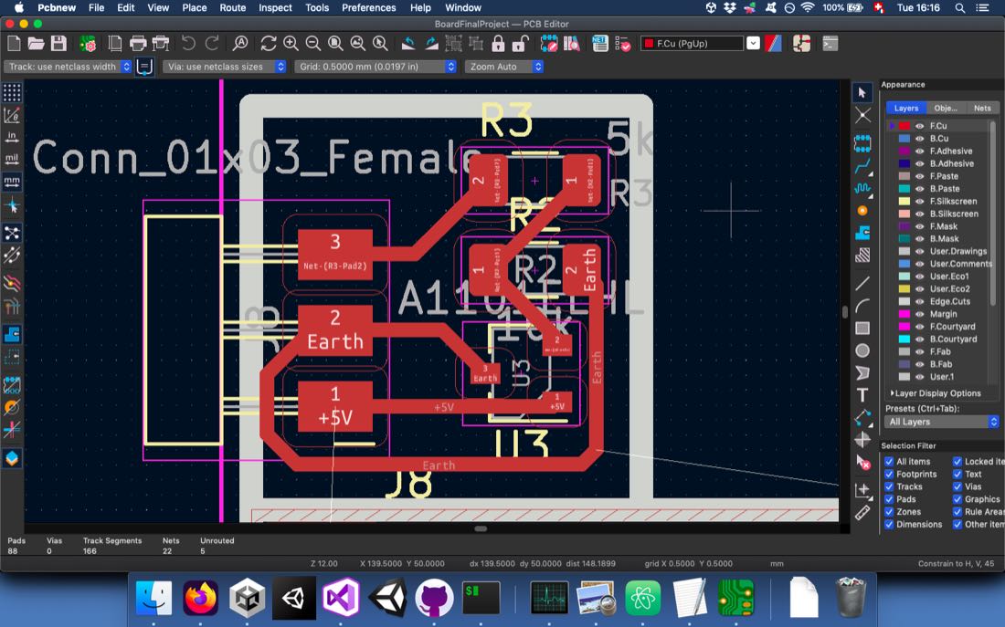
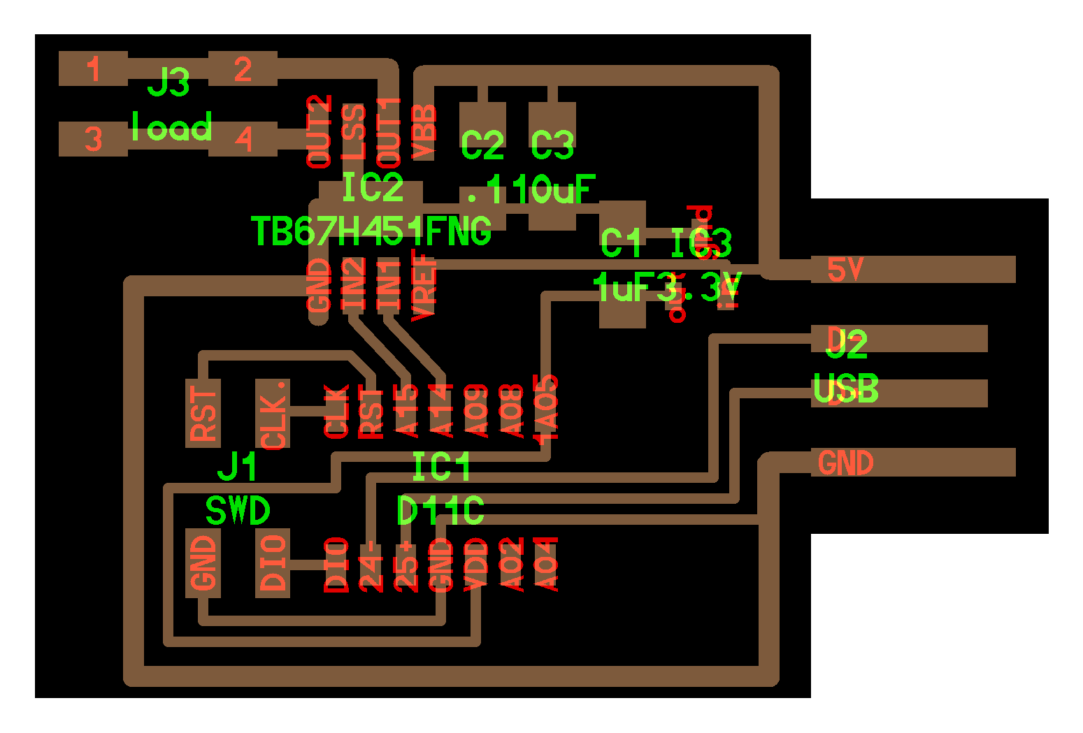
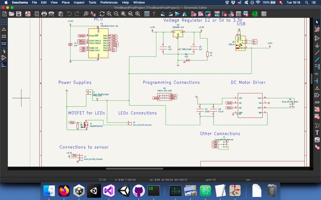
With this in mind, I started sketching my circuit.
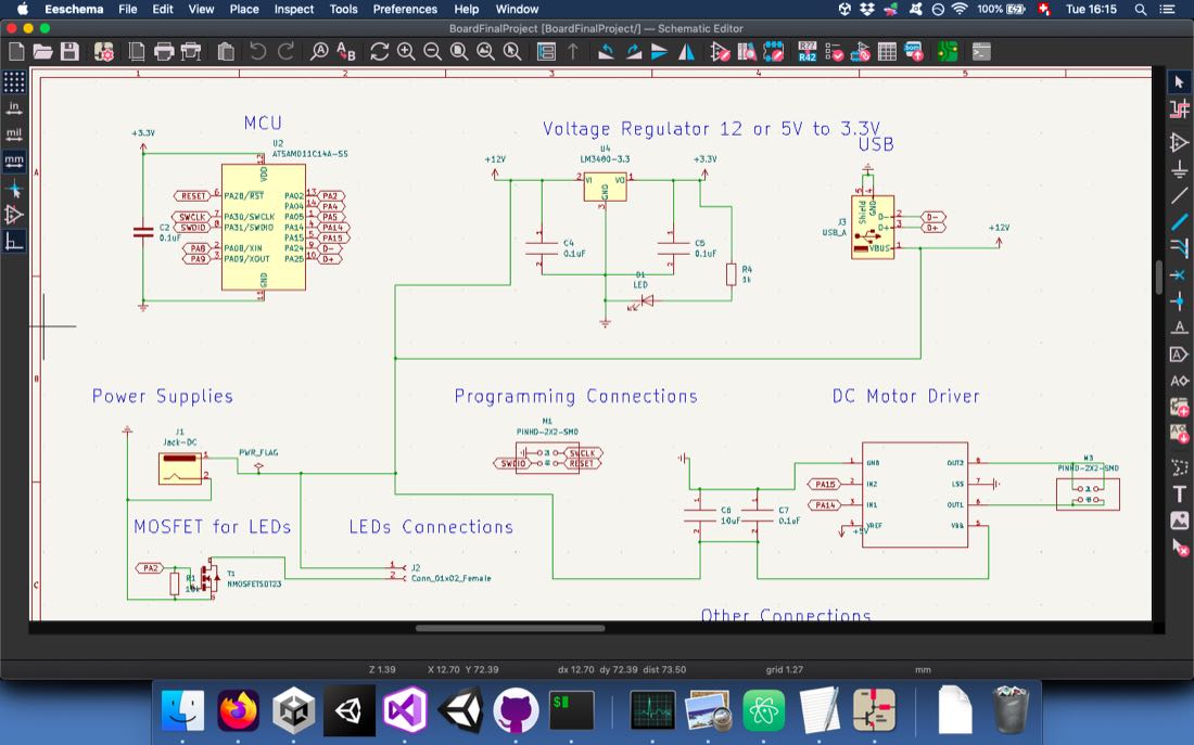
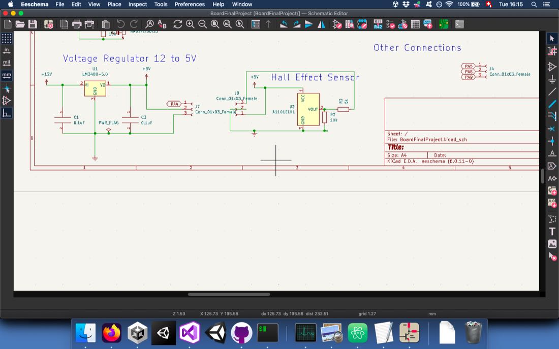
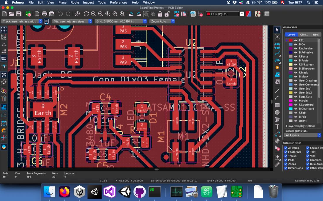
After my sketch was complete, I drew my PCB. Since I didn’t manage to connect everything, I would have to use some zero resistors.
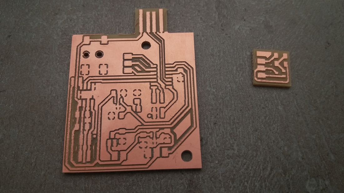
I chose to put my sensor on a separate board so that it would be easier to place close to the magnets:
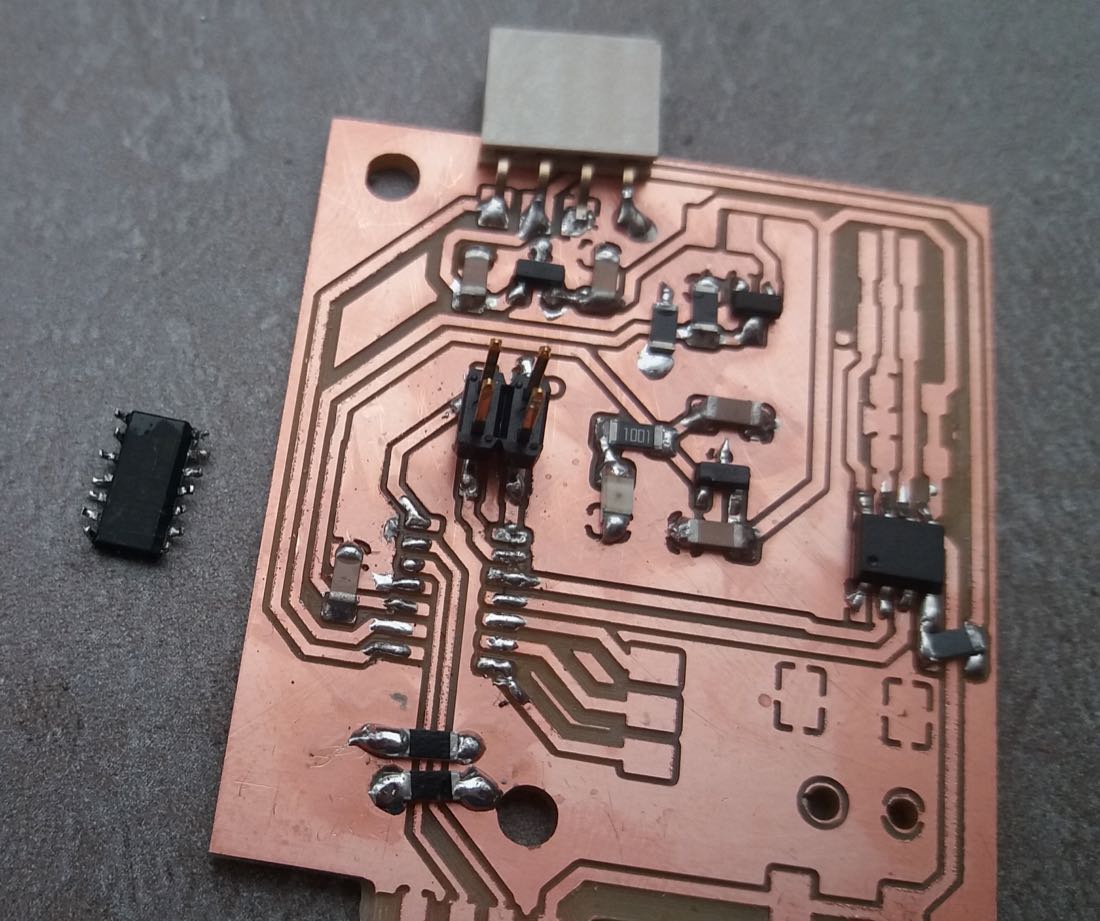
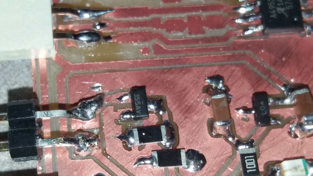
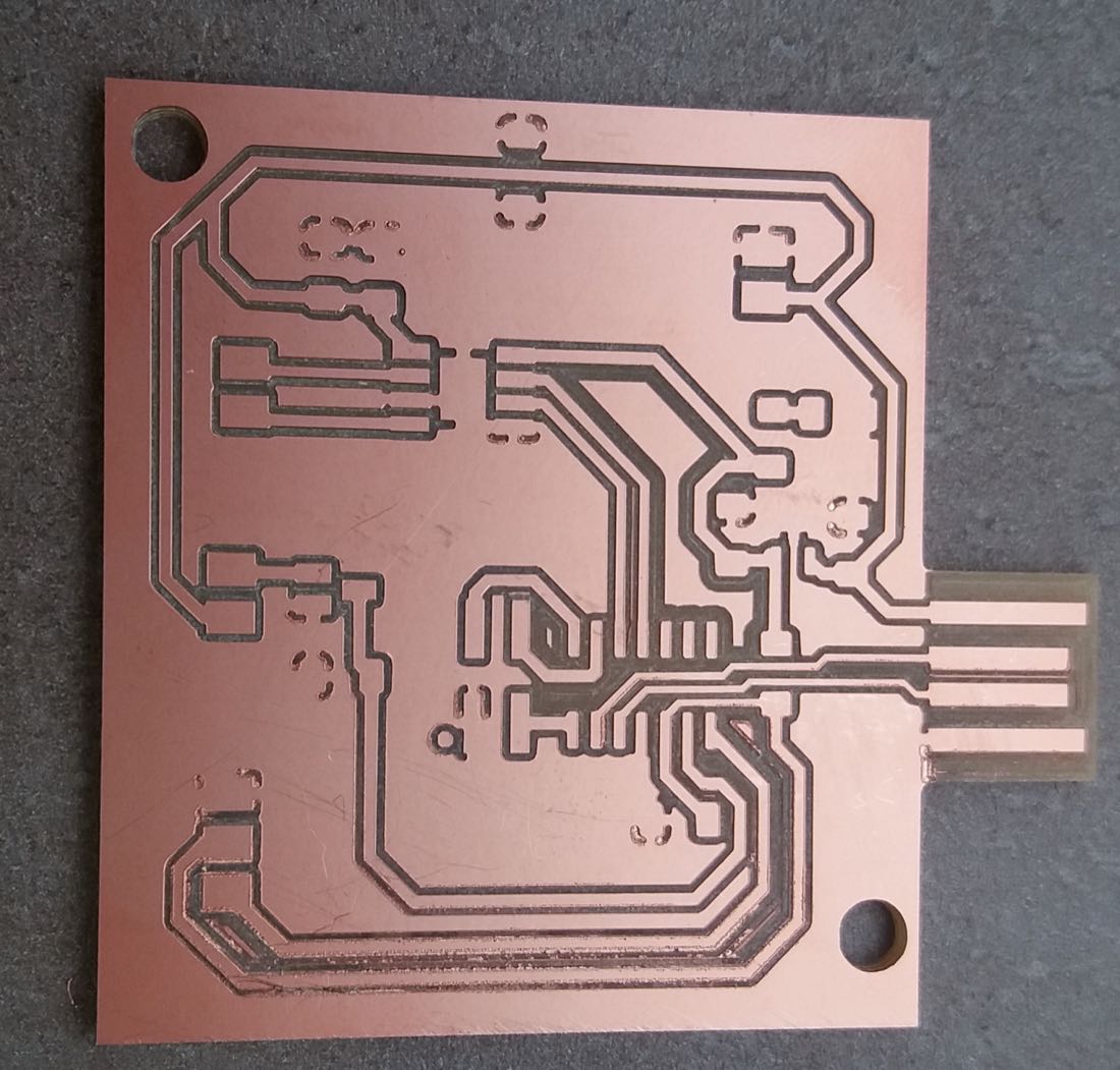
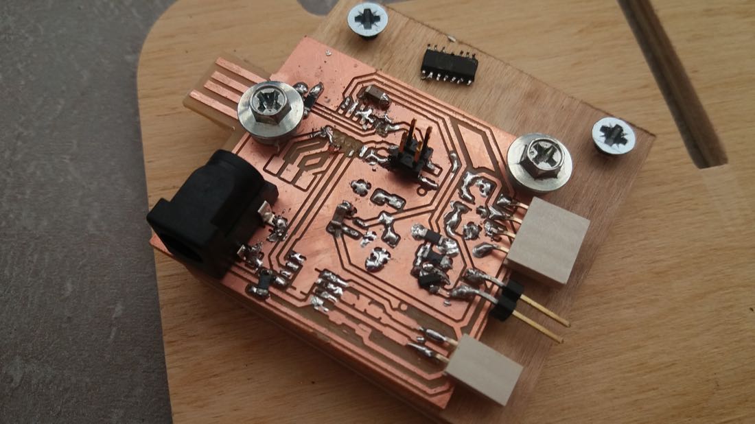
I could then carve and cut my boards.
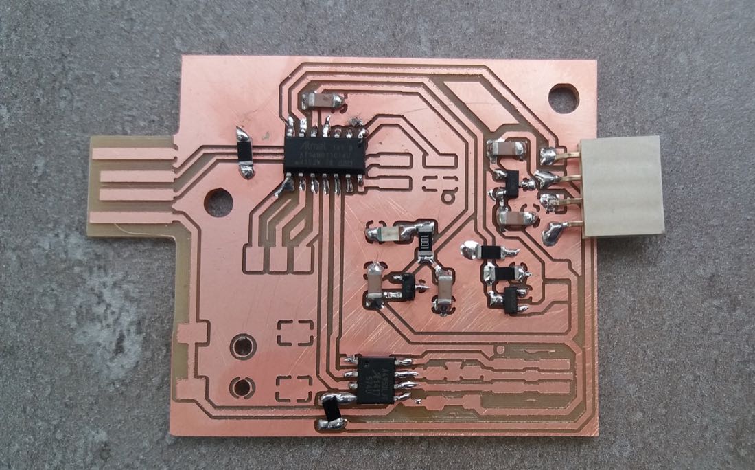
And solder the components.
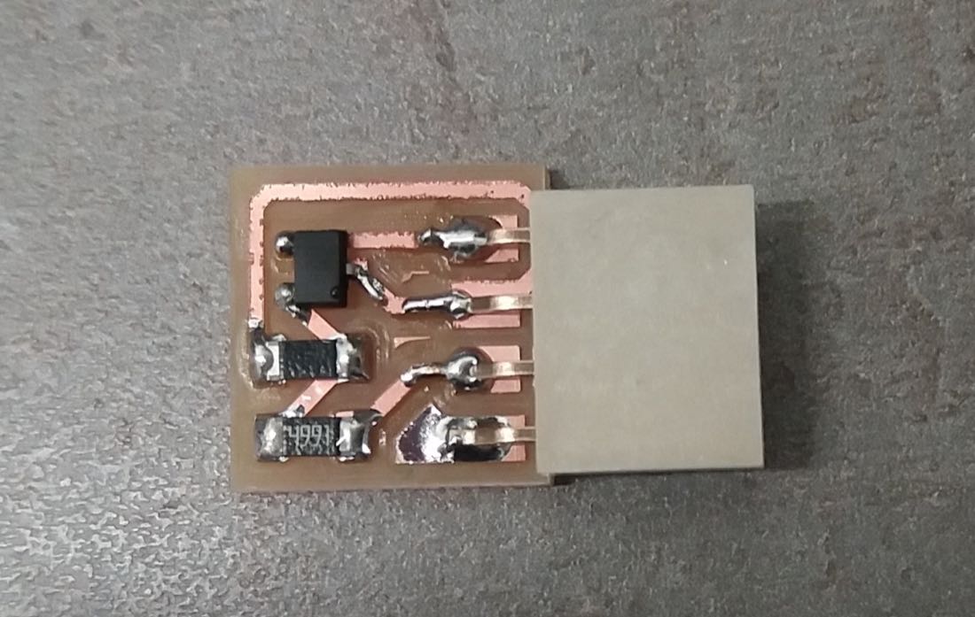
In order to make it more sustainable, I put some nail polish on the sensor board.

Unfortunately, when I tried to program it, I encountered some problem:
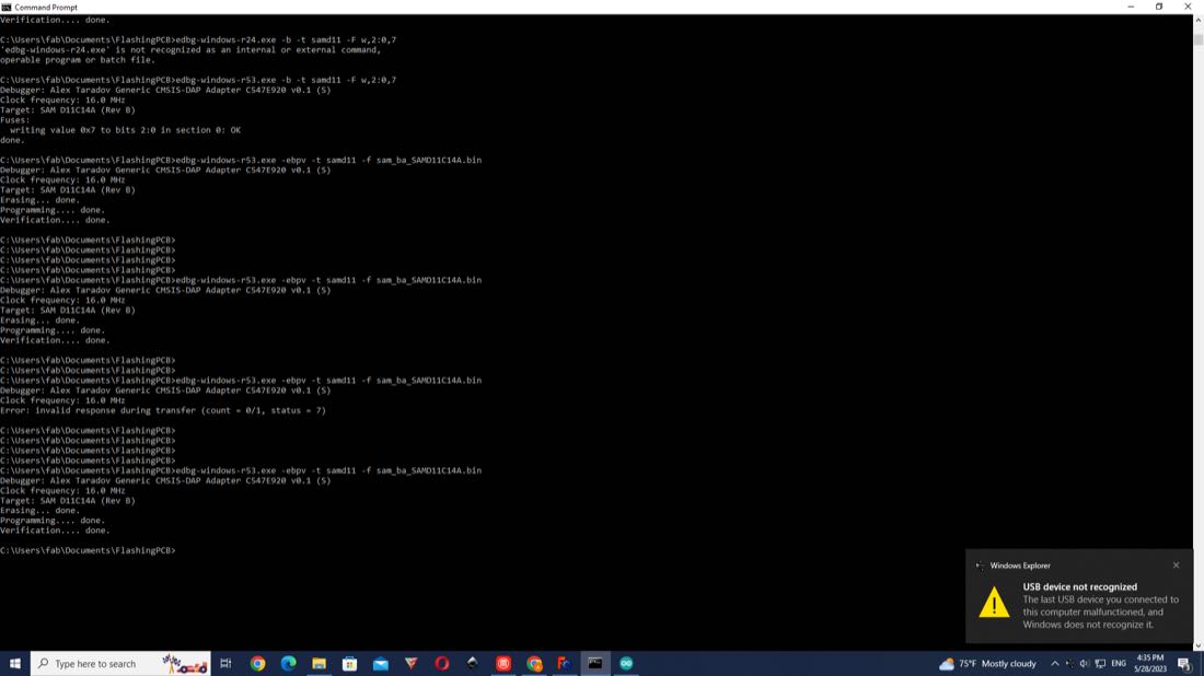
The programming of the microcontroller occured without throwing any error, but the microcontroller wasn’t recognised by the computer. After many unsuccessful trials, I decided to change the microcontroller, since it solved the problem when I did it with the ATTINY1614.
It seemed to work better in the beginning, but the problem remained. I was really puzzled since I had made several boards without encountering this issue. I tried to understand what was different this time, so I tried to remove the additional voltage regulator.
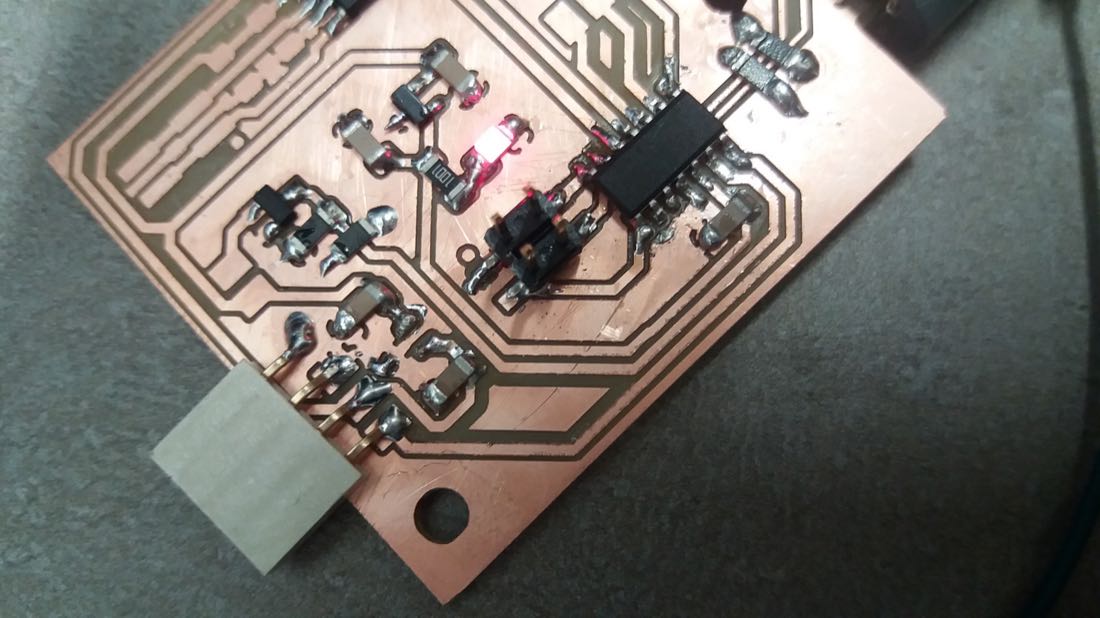
It seemed to be slightly better, since it was sometimes recognized, but not reliably. I removed additional components, without much effect.
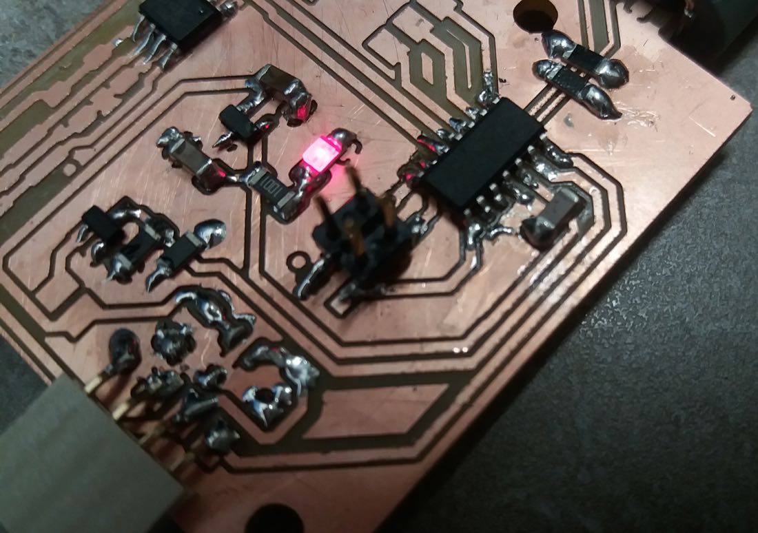
After a lot of searching, I remembered that in the examples given by Neil, the capacitors often are 1uF, instead of the 0.1uF I am putting (because the data sheet of the voltage regulator recommends 0.1uF). I tried to change this, and it worked!
Later, when I would test the whole device, my board would break. It seems that there was a shortcut inside the microcontroller between the Ground and Vcc. Since I removed a lot of components to find out what was the problem and damaged my board in the process, I had to make a new one. I designed a new one that would take into account what I learnt from the first version.
Despite a simplification of the circuit, I would still need some zero resistors.
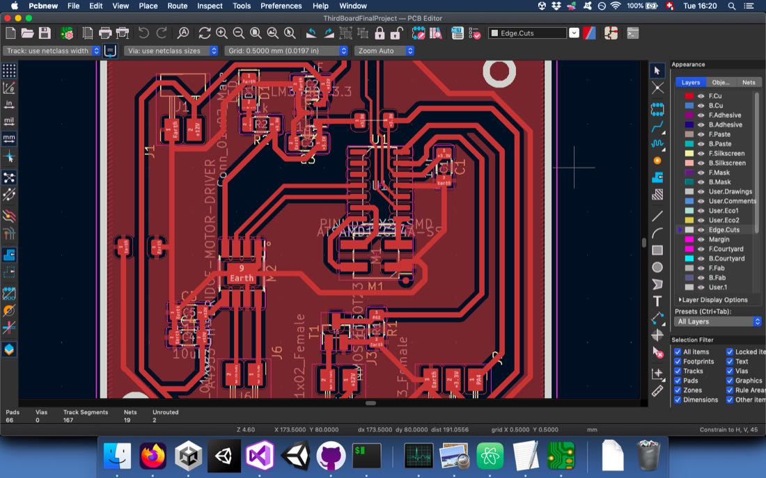
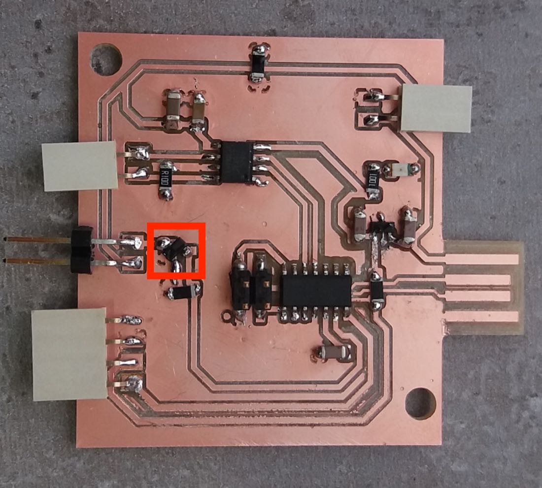
I carved it:
And soldered the components. I had some problem with the MOSFET transistor. The footprint I had in KiCad didn’t correspond to the transistor I wanted to solder. Some legs had to be swapped. To solve this, I had to solder it “on the back”.
Assembling
Frame Structure
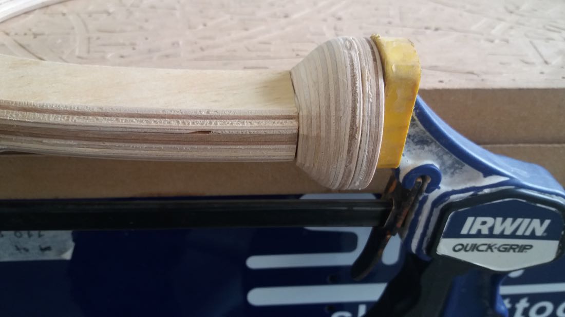
I started by assembling part that would hold the rotating axis. It was made of three parts. The part in the center was carved in order to hide some wire inside.
I glued these parts together.
Once this was done, I glued the part that was 3D milled and that contains the ball bearing.
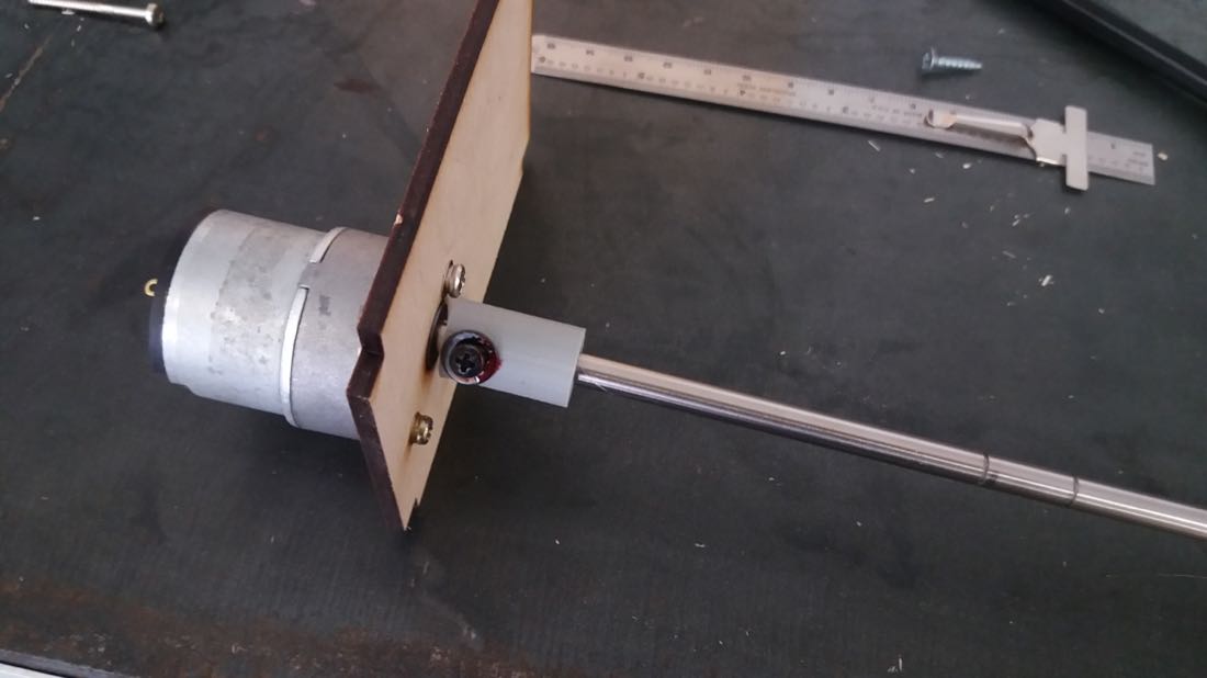
I secured the motor to the laser cut part using three screws. On the shaft, I screwed the 3D printed part that would rotate the axis.
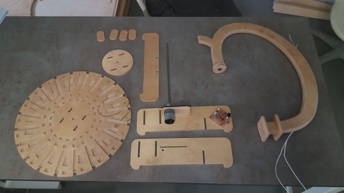
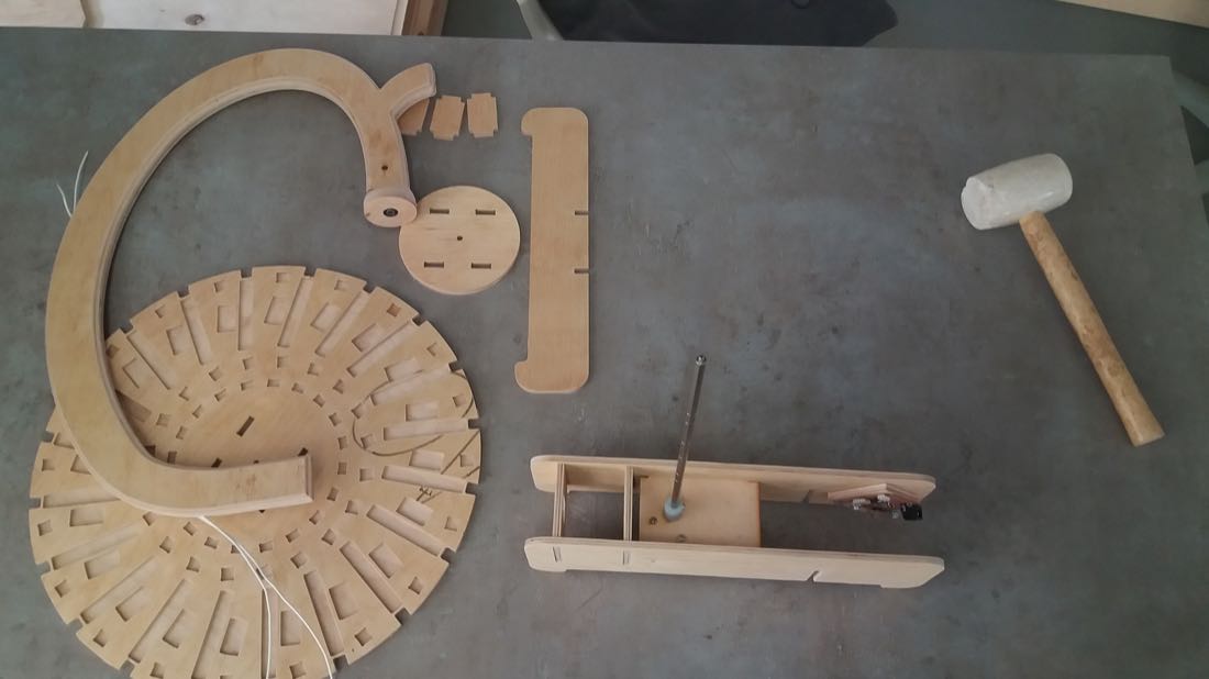
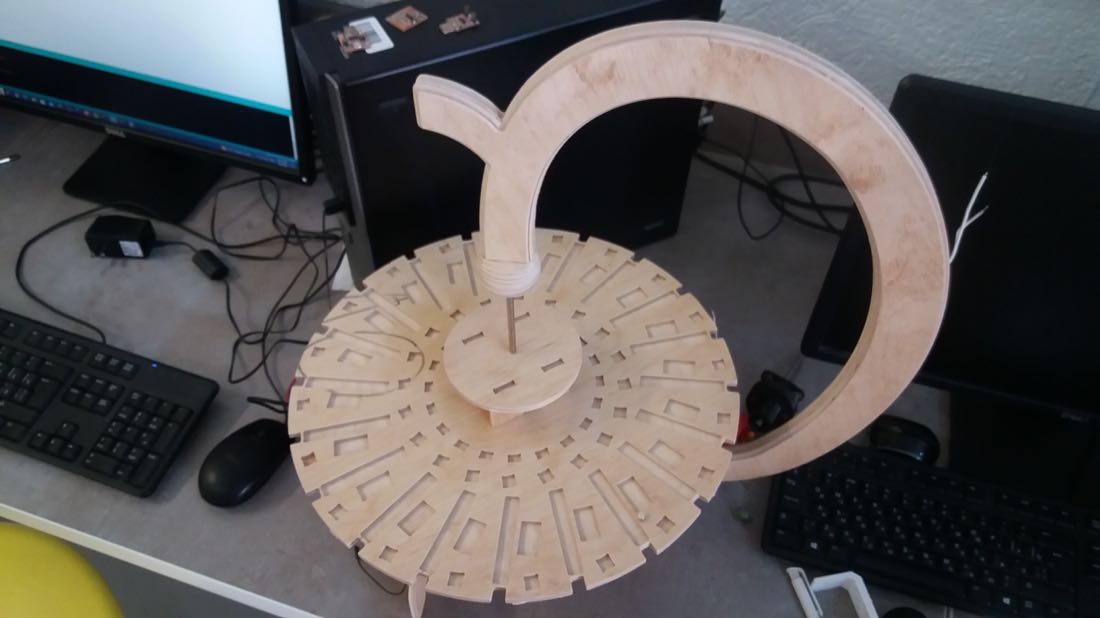
Most of the parts were now ready to be assembled.
I started by assembling parts that would hold the motor.
I put then the disk on the axis.
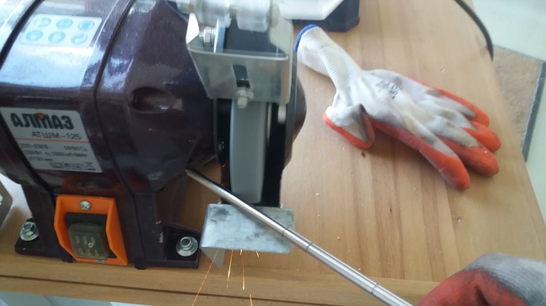
When I tried to put the axis insided the ball bearing, I noticed that it was slightly too long, so I cut the tip.
Afterwards, it was easier to assemble the whole.
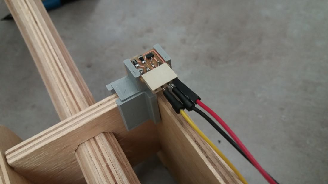
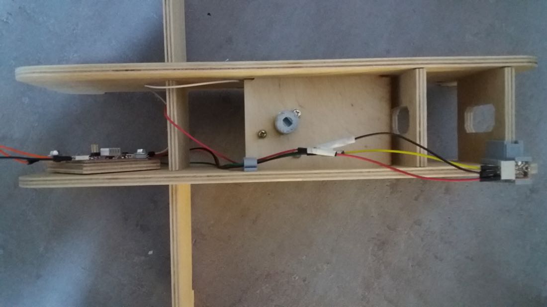
The PCB was screwed on one of the feet, facing inside so that it would be less visible (this photo is from the old PCB that would then be replaced).
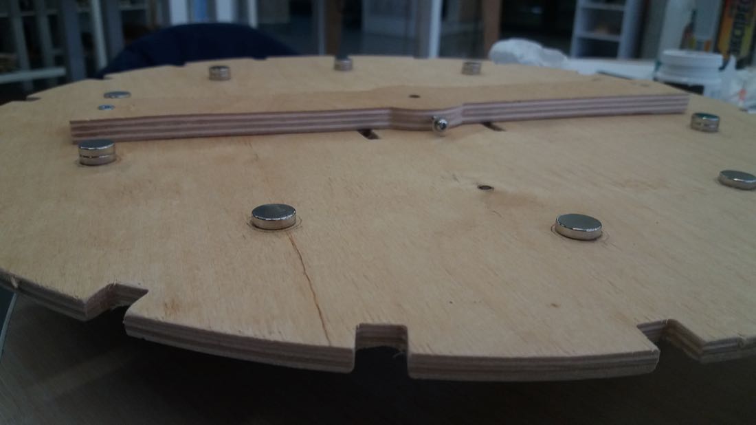
On the bottom face of the disk, I glued 10 magnets that could be detected by the Hall effect sensor in order to tune the frame rate of the LEDs flashes.
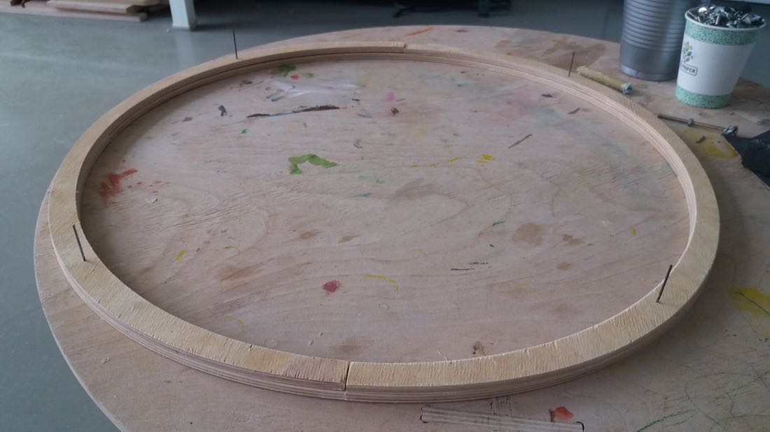
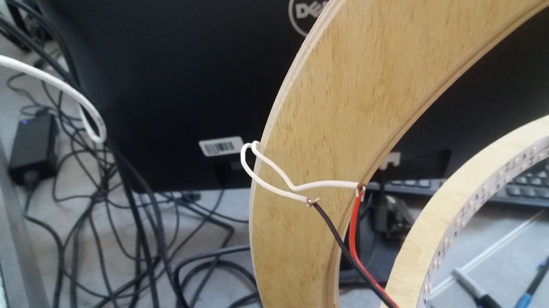
For the LEDs, I glued two rings together and later put the LEDs strip on the inner face of the ring.
I 3D printed a small mount for the sensor.
Painting all the 3D printed parts took a long time!
I also painted the disks.
I managed to cover and paint the hole caused by the weird issue I encountered with the Shopbot.
Once all the parts were painted, I sorted them by frame number.
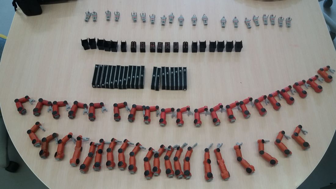
And started to assemble the scene.
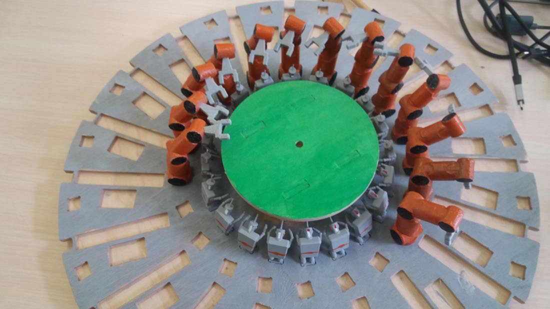
I tried to hide the wires inside the structure the best I could. I used some small 3D printed parts glued to the wood to prevent some wires to move too much.
The wires hidden inside the frame come out close to the wires from the LEDs.
Programming
I coded the zoetrope so that it keeps a constant speed for the DC motor and adjusts the frame rate of the LEDs flashes according to this speed.
//Acknowlwledgement:
// H-bridge D11C hello-world
// Neil Gershenfeld 11/8/22

// Modified by Maxime Richard

#define output(pin) (PORT->Group[0].DIRSET.reg = pin)
#define set(pin) (PORT_IOBUS->Group[0].OUTSET.reg = pin)
#define clear(pin) (PORT_IOBUS->Group[0].OUTCLR.reg = pin)
#define PWM_count 20 // number of PWM cycles
#define on_delay_slow() delayMicroseconds(20) // PWM on time
#define off_delay() delayMicroseconds(10) // PWM off time

#define IN1 PORT_PA15 // IN1
#define IN2 PORT_PA14 // IN2

//target frame rate
#define numberMagnets 10
#define numberFrames 20
#define targetFrameRate = 12;
uint16_t targetInterval = 1000 / 12;
uint16_t targetSignalInterval = numberFrames / numberMagnets * targetInterval;
uint32_t averageInterval = 1000;
uint32_t currentFrameInterval = 1000;


//Hall effect input device
#define input(pin) (PORT->Group[0].DIRCLR.reg = pin)
#define inputPin 4
#define numberSamples 2
#define thresholdSignal (520 * numberSamples)
#define deactivationThreshold (510 * numberSamples)

//frequency calculation
uint16_t beforePreviousInterval = averageInterval;
uint16_t previousInterval = averageInterval;
uint16_t currentInterval = averageInterval;
uint32_t lastThreshold = 0;
bool aboveThreshold= false;

uint16_t currentPulseWidth = 5;

//LED flash
uint32_t lastFlash = 0;
#define LEDPORT PORT_PA02
#define flashLength 10

//DEBUG
uint32_t stopWatch = 0;

void setup() {
  output(IN1);
  output(IN2);
  output(LEDPORT);
  pinMode(inputPin, INPUT);
  clear(IN2);

  Serial.begin(9600);
}

void loop() {
  stopWatch = micros();
  //turn on LEDs
  uint32_t currentTime = millis();
  bool ledOn = false;
  if ((currentTime - lastFlash) > currentFrameInterval) {
     lastFlash = currentTime;
     set(LEDPORT);
     ledOn = true;
  }

  //drive motor
  for (int i = 0; i < PWM_count; i++ )
  {
    set(IN1);
    delayMicroseconds(30);
    clear(IN1);
    off_delay();
  }


  //process input
  uint32_t inputSignal = 0;

  for (int i = 0; i < numberSamples; i++) {
     inputSignal += analogRead(inputPin);
  }
  //Serial.println(inputSignal);

  if (inputSignal > thresholdSignal) {
    if (!aboveThreshold) {
      Serial.println("threshold!");
      aboveThreshold = true;
      uint32_t current = millis();
      beforePreviousInterval = previousInterval;
      previousInterval = currentInterval;
      currentInterval = current - lastThreshold;
      lastThreshold = current;

      averageInterval = (beforePreviousInterval + previousInterval + currentInterval) / 3;
      currentFrameInterval = averageInterval / 2;
    }
  } else if (inputSignal < deactivationThreshold) {
    aboveThreshold = false;
  }

  if (ledOn) {
    clear(LEDPORT);
  }


  Serial.print("cycle duration: ");
  Serial.println((micros() - stopWatch));
}
Bill of materials
| Material/Component | Origin | Shop link | Approximate Price [$] |
|---|---|---|---|
| ELECTRONICS | 48.66 | ||
| SAMD11C | our lab | digikey | 2 |
| 12V power supply | our lab | wildberries | 8 |
| LEDs | our lab | wildberries | 20 (7700AMD) |
| DC motor | our lab | jameco | 15.95 |
| motor driver | our lab | digikey | 1.91 |
| Hall effect sensor | our lab | digikey | 0.8 |
| ZOETROPE | 44 | ||
| 3D printed objects | our lab | 20 | |
| paint | local shop | 3 | |
| 6mm Plywood | our lab | 10 (4000AMD) | |
| 20 x magnets | our lab | wildberries | 11 |
| Support | 5.5 | ||
| Plywood (same as for zeotrope) | - | ||
| bearing | recycled from old printer | aliexpress | 0.5 |
| 6mm metal axis | recycled from old printer | aliexpress | 5 |
| TOTAL | 98.16 |
License
This work is licensed under Creative Commons Attribution 4.0 International (CC BY 4.0) .
You are free to:
-
Share — copy and redistribute the material in any medium or format
-
Adapt — remix, transform, and build upon the material for any purpose, even commercially.
Under the following terms:
- Attribution — You must give appropriate credit, provide a link to the license, and indicate if changes were made. You may do so in any reasonable manner, but not in any way that suggests the licensor endorses you or your use.
Conclusion
These last three weeks were very busy. I was happy to be able to finish just on time before the presentation. I reduced a bit the scope of the initial project I had in mind, since I thought that I could add some more 2 animation.
The main thing that I would have done different is to make the scene less crowded and further away from the center. Indeed, it is hard to grasp the animation when watching closer to the center of the disk. A fix could have been to make the disk radius a bit bigger.
Another issue I am having is with video recording the animation. I had some ideas concerning how to fix this, but I didn’t have the time to try it out yet.