Week 3: Computer-Controlled Cutting
✓ characterize our lasercutter’s focus, power, speed, rate, kerf, joint clearance and types
✓ cut something on the vinylcutter
✓ design, lasercut, and document a parametric construction kit
Vinyl cutter
Logo design
I have tested the AI art generator stable diffusion for digital art and wanted to try it for logo design. I am using here a google colab notebook credited to AUROMIC111 and K4YT3X:
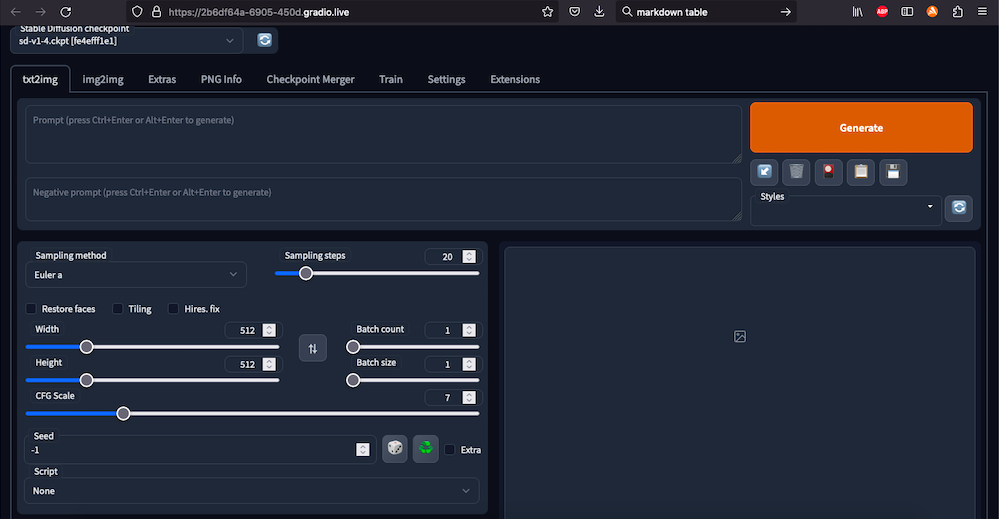
In order to generate logos, I used the text to image function with the following parameters:
| Parameter | Value |
|---|---|
| prompt | black and white logo of a metal band with a hammer and a CNC |
| sampling steps | 50 |
| CFG Scale | 14.5 |
| Sampling method | Euler a |
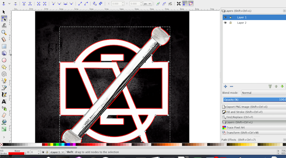
After few trials, I chose this abstract design:

I then imported this image into Inkscape and traced it using Bézier curves:
Setup
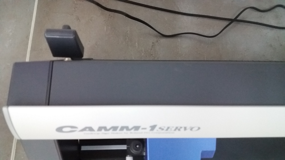
The printer of our lab is a CAMM1-Servo Roland GX 34:
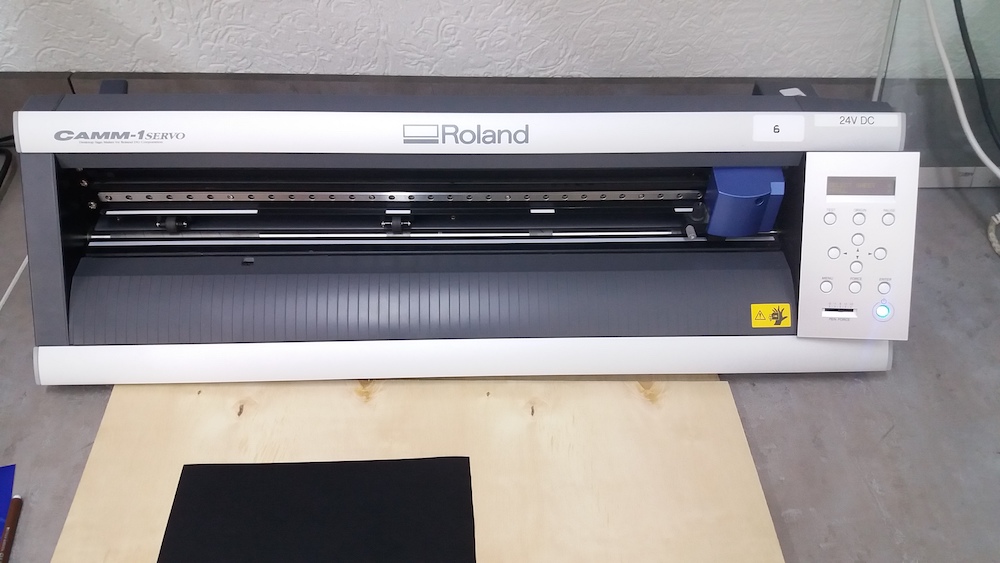
I chose a black vinyl for my logo and placed it on the vinyl cutter. I had to adjust the wheels so that there is enough vinyl on both sides of the wheel and that the wheel is above a gripping material:
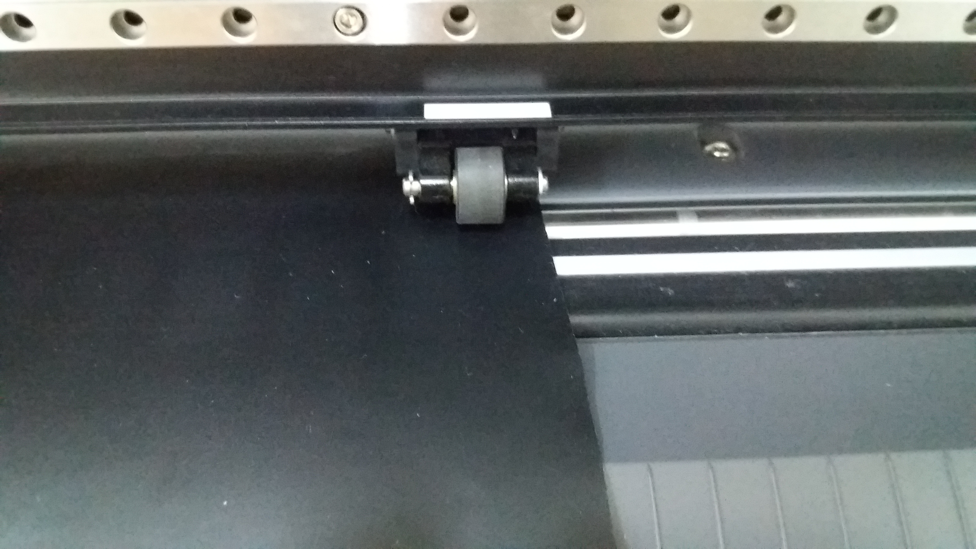
The orientation of the vinyl inside the cutter matters. Since it was rolled, “waves” can occur when trying to lay it flat and therefore, it should be fed in the direction perpendicular to these waves:
Once the vinyl sheet is well in place, I used a lever to bring the wheels down:
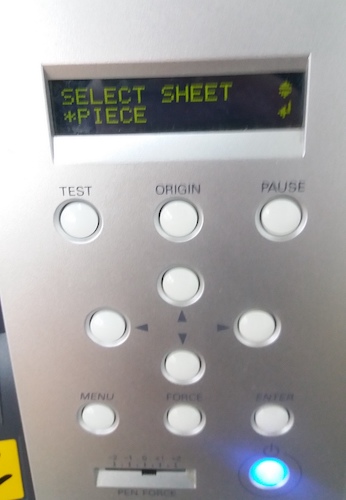
The machine can handle three different types of feeding:
- Piece
- Roll
- Edge
For my purpose, I selected “piece”:
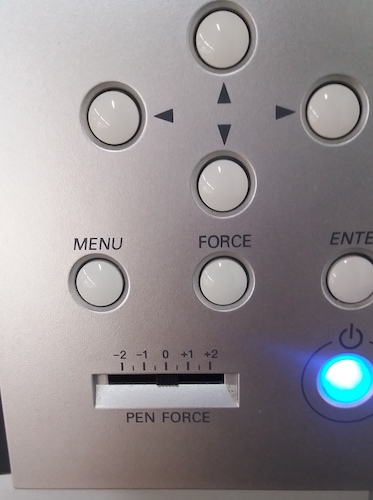
Then, the force of the blade on the sheet had to be tested. First, the “pen force” slider had to be centered on 0:
There is a standard test for this machine which cuts a disk inside a square. If one can remove the square while the disk stays in place, the force is adequate. I tried the following forces: 120gf, 130gf, 140gf, 150gf.
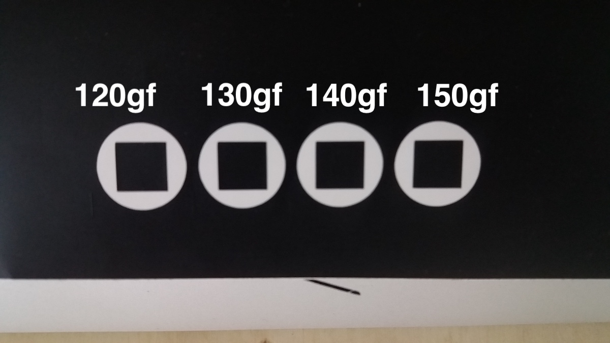
Since they all seemed to work, I chose one of the middle forces: 140gf.
Cutting
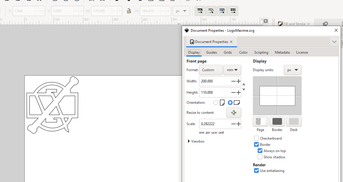
I imported my design on the computer dedicated to the vinyl cutter and opened it in Inkscape. I adapted its size and set the line thickness to hairline. I then changed the document size to approximately fit the vinyl sheet size.
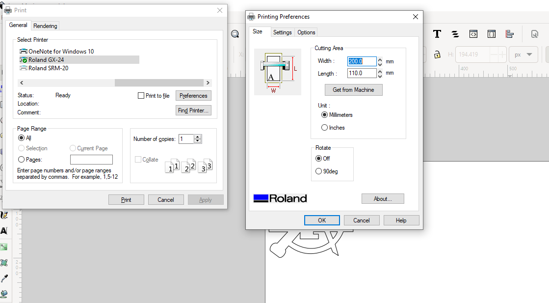
And when sending the printing job, I also had to specify the size:
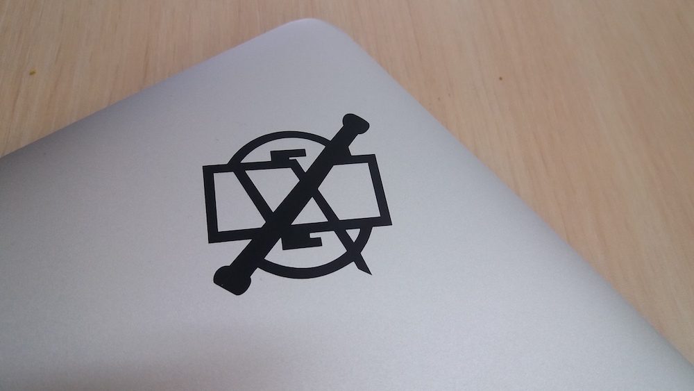
And here is the result:

NOTE
If a shape is not getting cut, verify that the stroke is “hairline” and that it is a path (Path > Object to Path OR Path > Stroke to Path)
Laser cutter
Group assignment
For this group assignment, we had to characterize our lasercutter’s focus, power, speed, rate, kerf, joint clearance and types. Concerning the joint clearance and types, we each did it for the specifity of our construction kit and it will therefore be described in the corresponding section below.
Our laser cutter is an Epilog mini 24 with a laser power of 40W.
The cutting surface of the laser measures 24 by 12 inches, which corresponds to 609.6mm x 304.8mm.
Laser focus
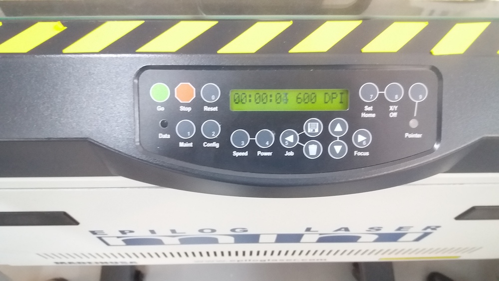
We adjust the laser focus for each jobs batch following this procedure:
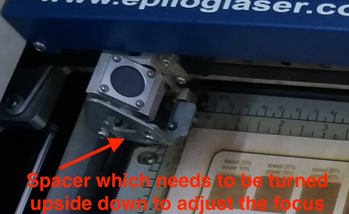
- Press focus on the laser cutter. The laser moves into starting position.
- Place the spacer on the laser head. It is maintained in place by magnets. Press the up and down arrows to lower or lift the head until the spacer is barely touching the material.
- Press Reset.
Laser power, speed and frequency
Our laser is quite moody and it is not uncommon that we need to restart a job many times before it starts cutting/engraving.
We tested these parameters for three different types of material: 4mm cardboard, 4mm plywood and 6mm acrylic. Our colleague Rudolf Igityan has some experience working with this laser and his insights were very useful when choosing some adequate values to test:
Cardboard:
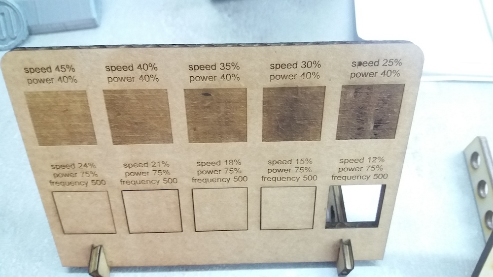
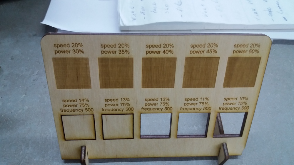
Plywood:
Acrylic:
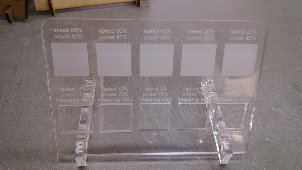
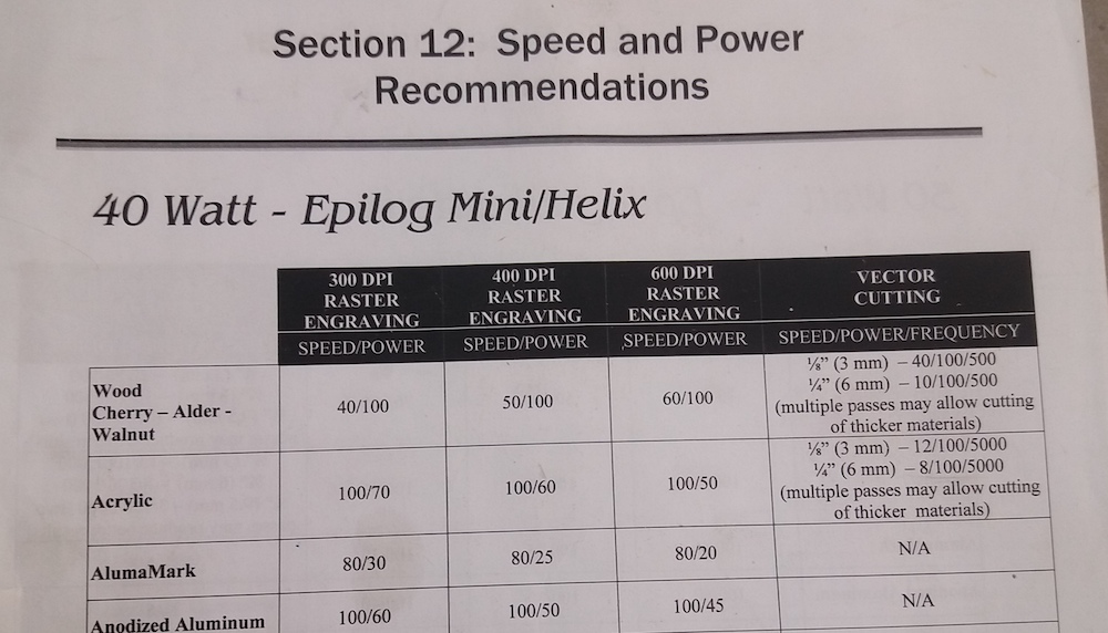
Since our laser struggles to be consistent when running at high power, we are using lower powers and adapting the other parameters to achieve adequate cutting or engraving. Our settings differ significantly from the recommended parameters provided in the manual:
Kerf
The kerf corresponds to the diameter of the laser beam at the position where it intersects the material being cut. We planned this measurment at the last minute and unfortunately, a fire broke out in the Fablab the day we wanted to do it and the residue from the fire extinguishers made the laser cutter unusable for the remaining time. We went to another lab to carry out this measurment but the value obtained last year on the laser cutter I used for the rest of this assignment was 0.197 mm.
In order to measure the kerf, we cut an array of eleven rectangles of each 10 mm width. Then, we first measured the width of all the rectangles side by side:
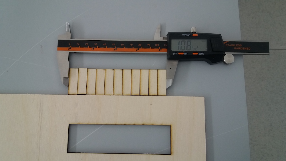
We obtained 108.52 mm. Therefore, (110 - 108.52) / 11 = 0.135 mm kerf. We also measured with a micrometer (and this is a video which helped us undestand how to use this tool):
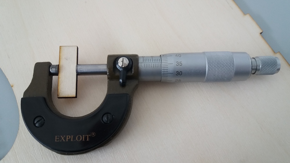
We obtained 9.860 mm. Therefore, 10 - 9.860 = 0.140 mm kerf. The two results are not exactly the same but are close.
Construction kit
Comb for joints testing
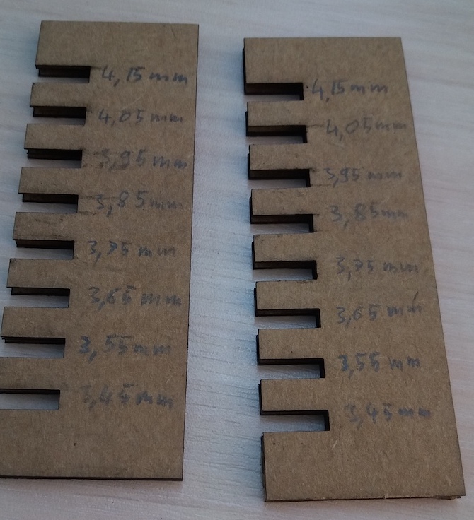
Before making the construction kit out of cardboard, I had to determine the appropriate finger joint width. In order to do so, I first measured the thickness of the cardboard that I would use.
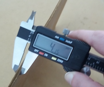
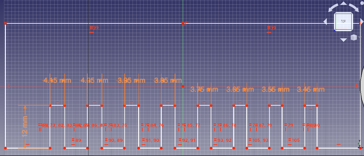
Since it was 4.15 mm, I sketched a comb with eight different finger joint width ranging from 4.15 to 3.45 mm in FreeCAD:
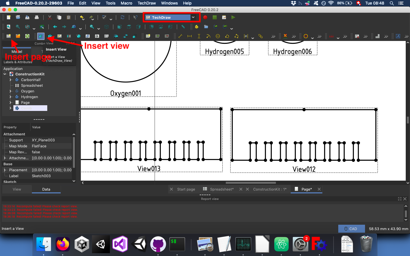
I wanted to export it to .svg to send it to the laser cutter. In order to do this, I had to use the TechDraw workbench, create a new page and press insert view for each comb I wanted to cut:
I then exported the page to .svg format and sent it to the computer dedicated to laser cutting. The laser cutter needs to get the print job from CorelDRAW in order to work. So I first imported my sketch into this software. Before I imported my design, I made sure that the “working sheet” had the same dimensions as the “work bed” of the Epilog-Laser Mini:
24in x 12in
or
609.6 x 304.8 mm
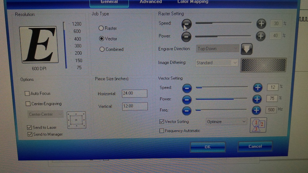
For some reason unknown to me, all my elements had double lines. I removed one of the lines and then set the line thickness to 0.1 mm because a higher value would let the laser cut more than once on each line. When the file was ready, I had to send the print job and set the laser settings. Since I am printing a vector drawing, I selected the vector cutting and set the frequency to 500, the power to 75% and the speed to 12%:
I then proceeded like this:
- Press focus on the laser cutter. The laser moves into starting position.
- Set the spacer on the laser head and press the up and down arrows to lower or lift the head until the spacer is just touching the material.
- Press Reset.
- Turn on the two filter pumps!
- Close the cover and press Go.
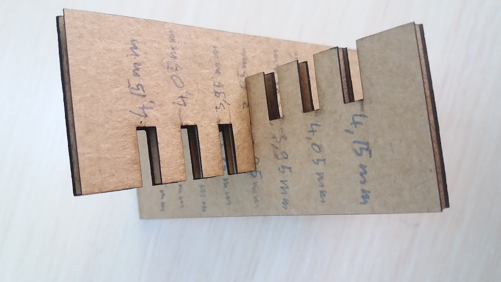
Once the combs were ready, I could test what would be the best finger joint width. In this case, it was 3.85mm:
Designing and cutting the construction kit
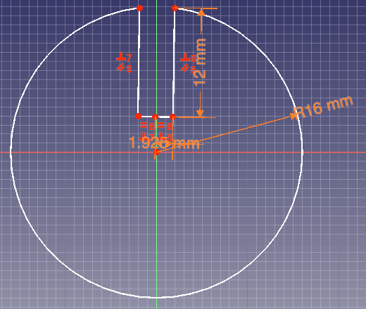
I thought of making a crude molecule construction kit with two atoms of carbon, one of oxygen and six hydrogens. To give a sense of the different sizes of each atom, I took the size of the covalent single bond from this wikipedia table. For the joint depth, I chose an arbitrary size of 12mm. I then started to sketch the parts.
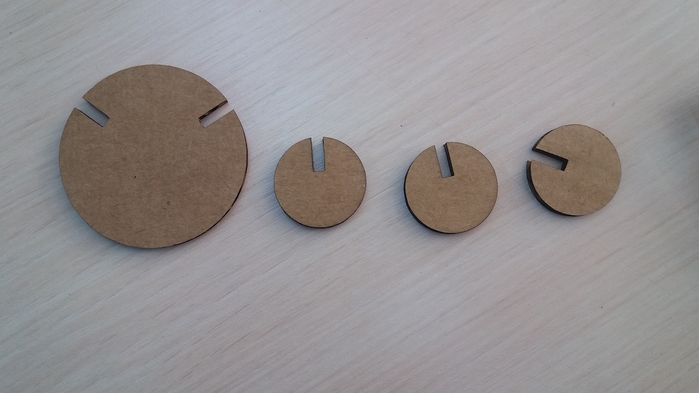
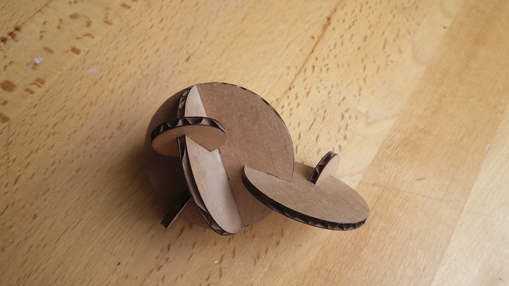
The carbon atom, because of its tetrahedral geometry, is made of two identical parts which will then be joined together:
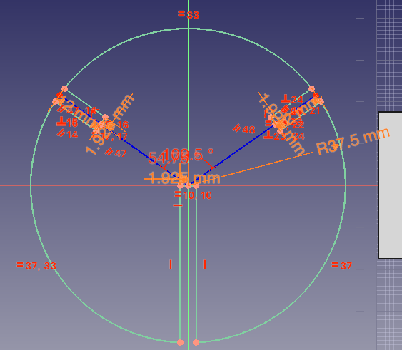
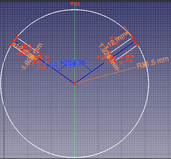
The oxygen atom can form two bonds with an approximate angle of 109.5°:
The hydrogen atom only forms one bond:
The parameters for these parts, as well as for the joint testing comb are the following:
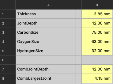
Following the same procedure as for the combs, I laser cut the different parts:
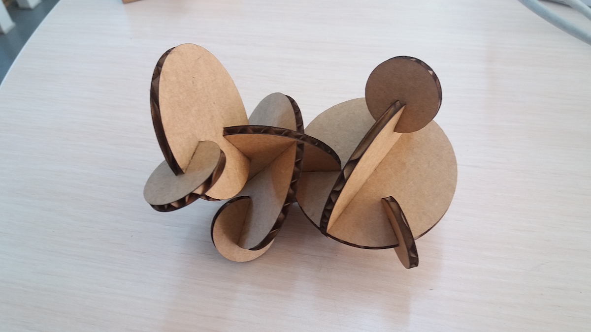
As examples, I assembled three molecules: ethanol, dimethyl ether and methanol.
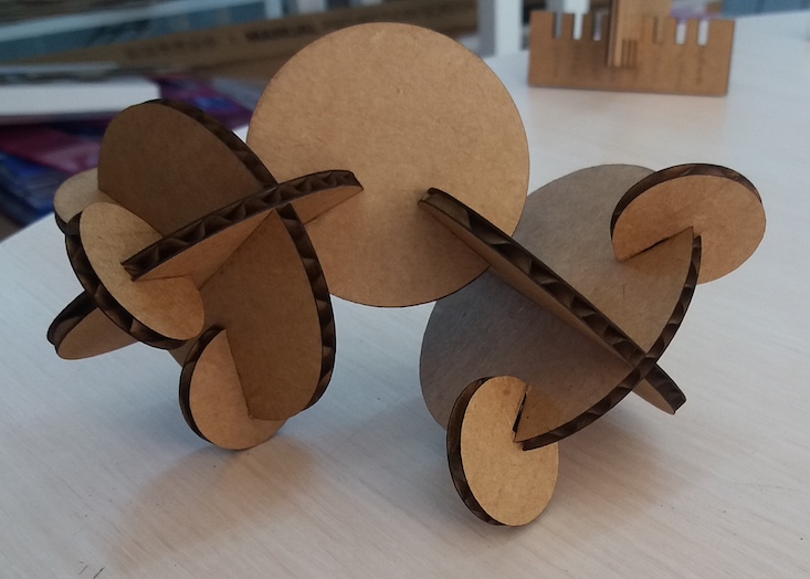
Thoughts about this molecule model
This model has a major inaccuracy in the bond length. Indeed, the overlap caused by the joints shortens significantly the distance between atom centers. This could be easily fixed by adapting the atom sizes and joints depth.
Another issue, probably more problematic for students, is the 2D shape of the atoms. This might indeed make the 3D reality of atoms harder to grasp.
Then, the uniform brown color of cardboard makes it hard to distinguish between different atom types. This could be fixed by painting the cardboard with the usual colors (black for carbon, red for oxygen and white for hydrogen).
However, the overlap makes it a better representation of the orbital overlap of molecules in comparison to the “balls and sticks” model.
In conclusion, this model, as it is quite abstract, would be probably not adequate to use in the classroom for beginners. It could however be used to test a deeper understanding of molecule structures. When teaching abstract concepts, it is indeed good practice to use different models to prevent the construction of incorrect ideas (e.g. oxygen is not red in reality).
Conclusion
Almost everything was new to me this week. Even when using FreeCAD, which I already did last week, I’ve learnt new things. I wish I would have cut more things with the laser, but the time was too short. One of the challenges of this week was to deal with the laser which often had trouble starting cutting.
Files of the week
SVG file of the logo for the vinyl cutter
SVG file of the construction kit
Freecad file of the construction kit