Week 15: Wildcard Week
✓ Design and produce something with a digital fabrication process (incorporating computer-aided design and manufacturing) not covered in another assignment, documenting the requirements that your assignment meets, and including everything necessary to reproduce it.
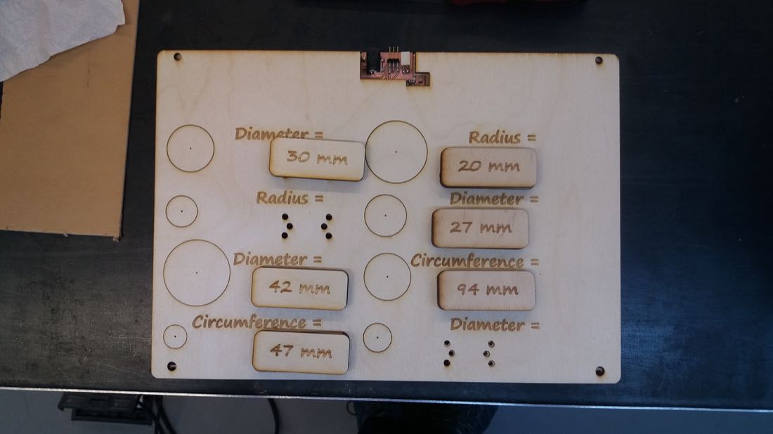
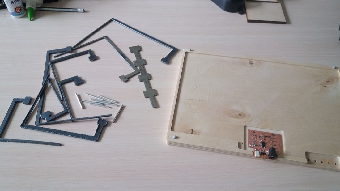
For this week, we went one day to a factory in Yerevan, the capital city of Armenia,to have access to a plasma cutter. I had in mind for some time the idea of making an educational game where a kid could have a direct feedback on his answers. At first, I didn’t really know how to integrate some metal cutting to this project, but after having given it some thoughts, I set up myself to cut some large “PCB tracks”. I knew that it might be challenging to cut such small parts on this kind of machine, but the problems occured at an unexpected step. Indeed, this week’s project was unfortunately a failure :-(
Designing the models
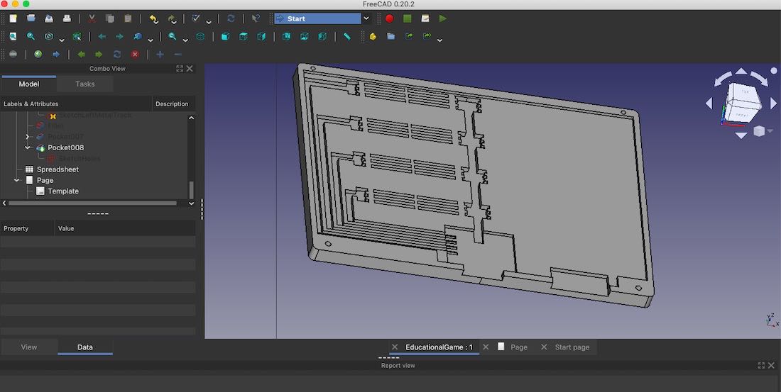
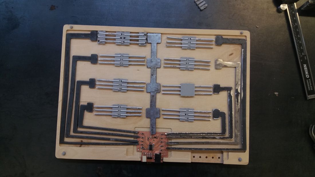
I designed the main part of my project in Freecad. This block would be carved inside 12mm thick wood with the Shopbot CNC. It would then contain the PCB and the steel and aluminium connections. In the same file, I sketched the connection that should be cut by the plasma CNC. They are here pocketed into the wood, because FreeCAD on my laptop doesn’t let me pad more than one separate solid (though I remember that I could do it on a PC):
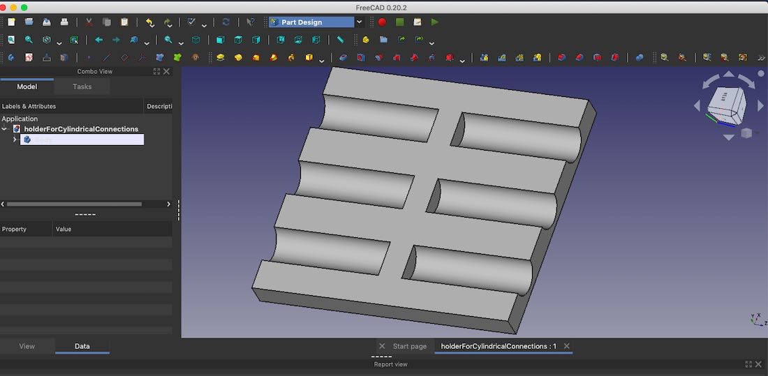
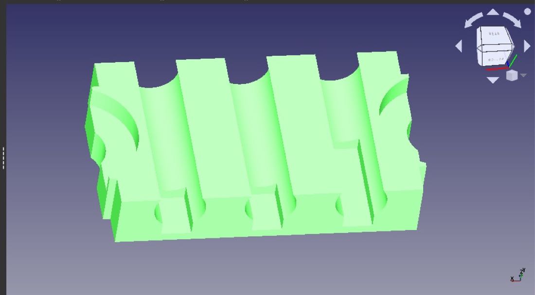
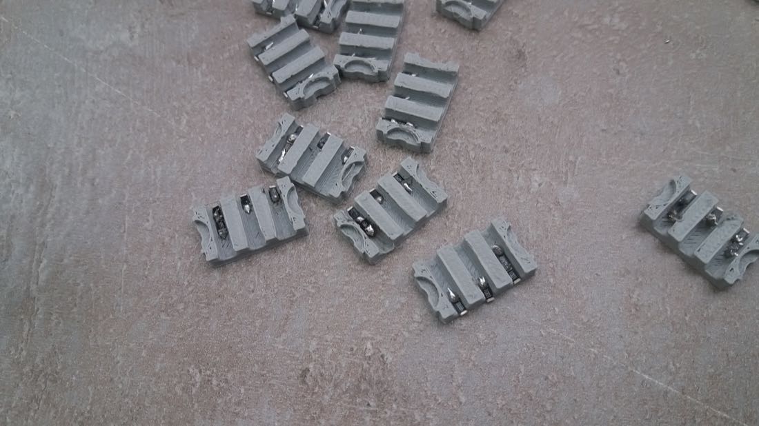
I also needed some 3D printed parts to hold the smaller parts of the connections:
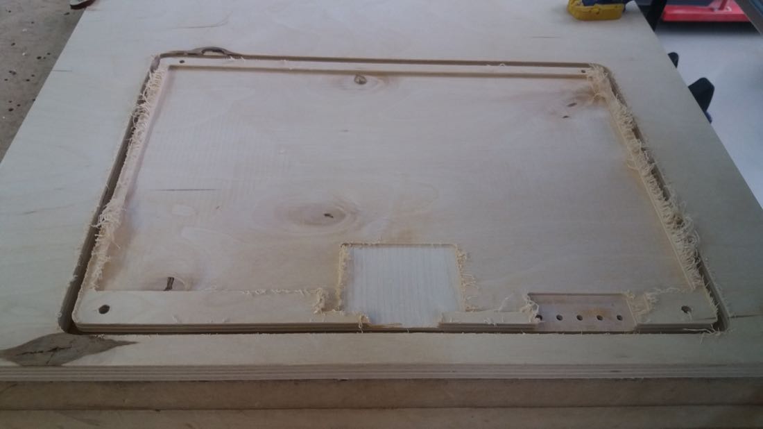
Cutting the main block with Shopbot
Once my design file was ready, I wanted to use the Shopbot to cut my design. While I was preparing my jobs on VCarve pro, the computer suddenly turned off and I couldn’t start it again. We experienced few power cuts during the morning and I was afraid that something was damaged. After consulting with Babken, we guessed that something was wrong with the power supply and decided to use the power supply of an other computer to try restarting the one of the Shopbot. After few unsuccessful trials, I was eventually able to restart it. What a relief!
I could then cut my part without porblem:
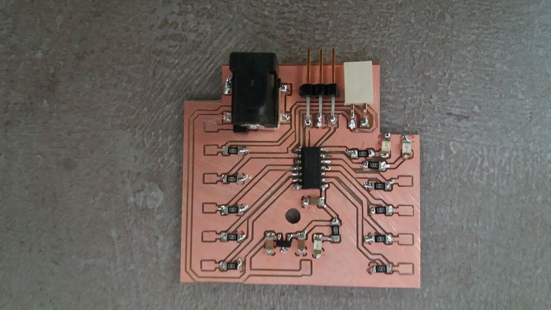
Making the board
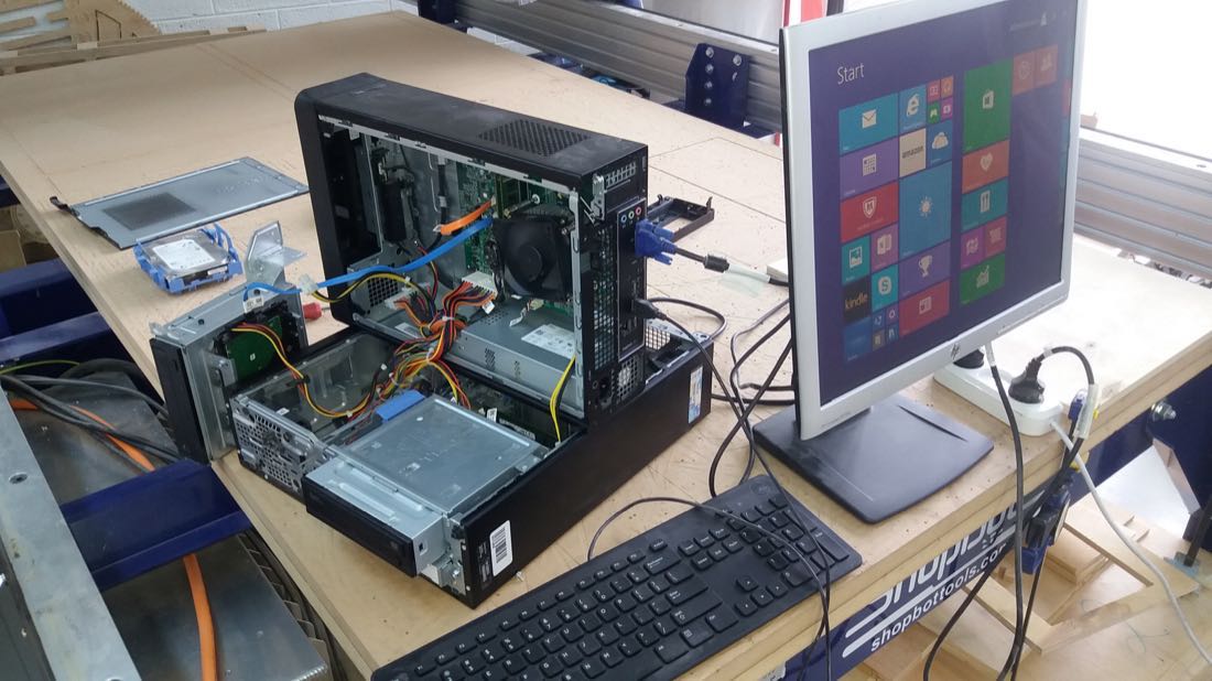
I cut and soldered the components without major issue:
Unfortunately, when trying to program the board through UPDI, I had an error:
avrdude: bad response to AVR sign-on command: 0xa0
avrdude: retrying with external reset applied
avrdude: bad response to AVR sign-on command: 0xa0
avrdude: retrying with external reset applied
avrdude: JTAGEN fuse disabled?
avrdude: initialization failed, rc=-1
         Double check connections and try again, or use -F to override
         this check.
After few unsuccessful trials, I declared my microcontroller dead and tried to desolder it:
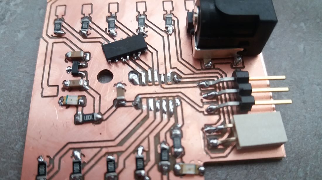
And soldered another ATTINY1614, which worked!
Plasma cutting
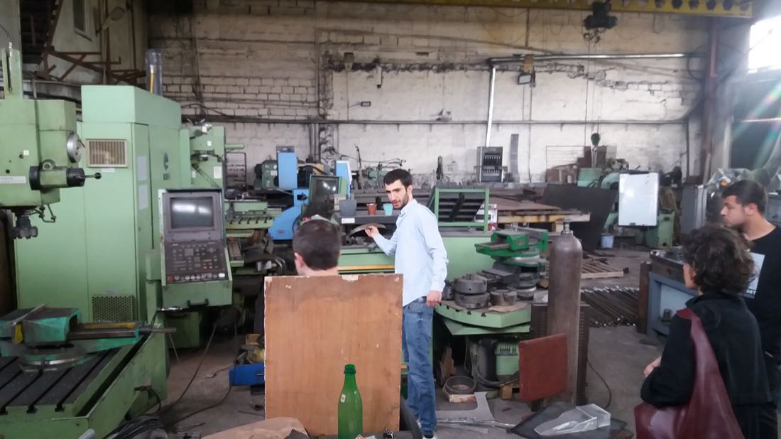
This week, we were lucky to visit Ashot’s factory (he is a former Fabacademy student). He has many cool machines, some of them even date back to USSR:
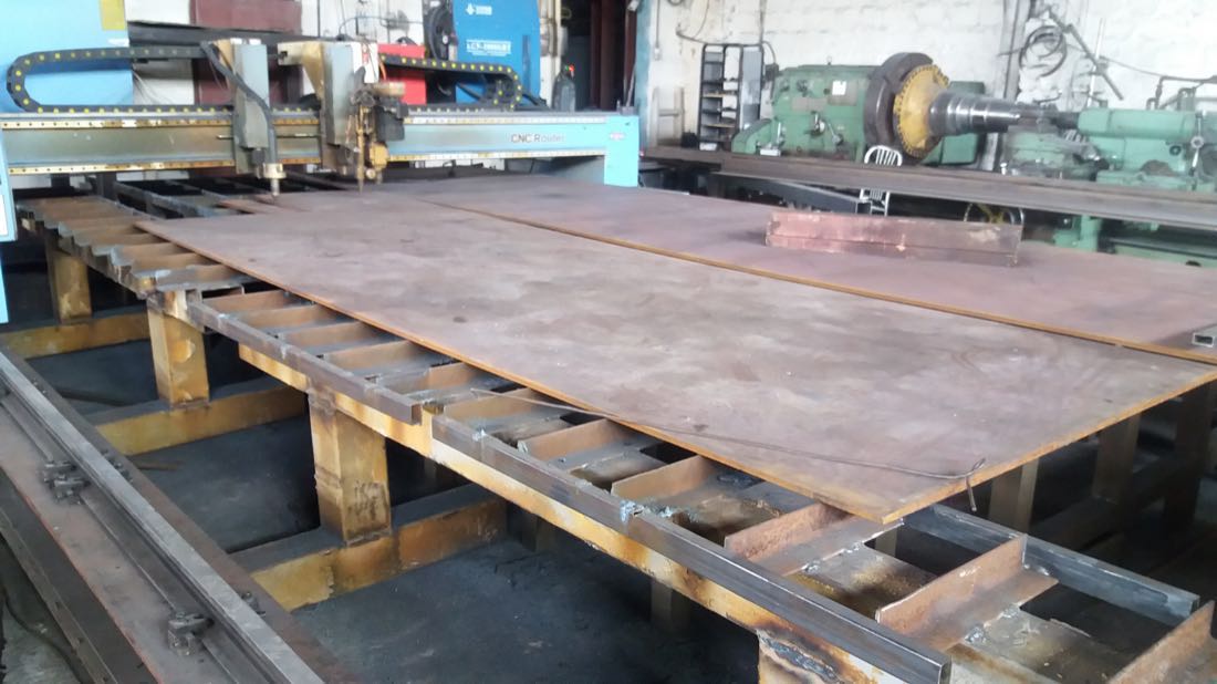
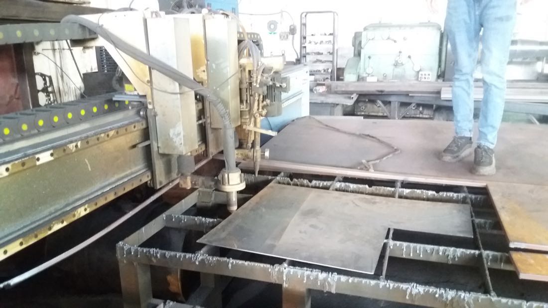
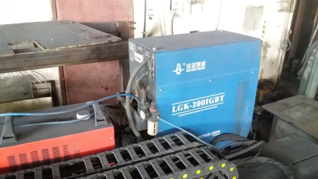
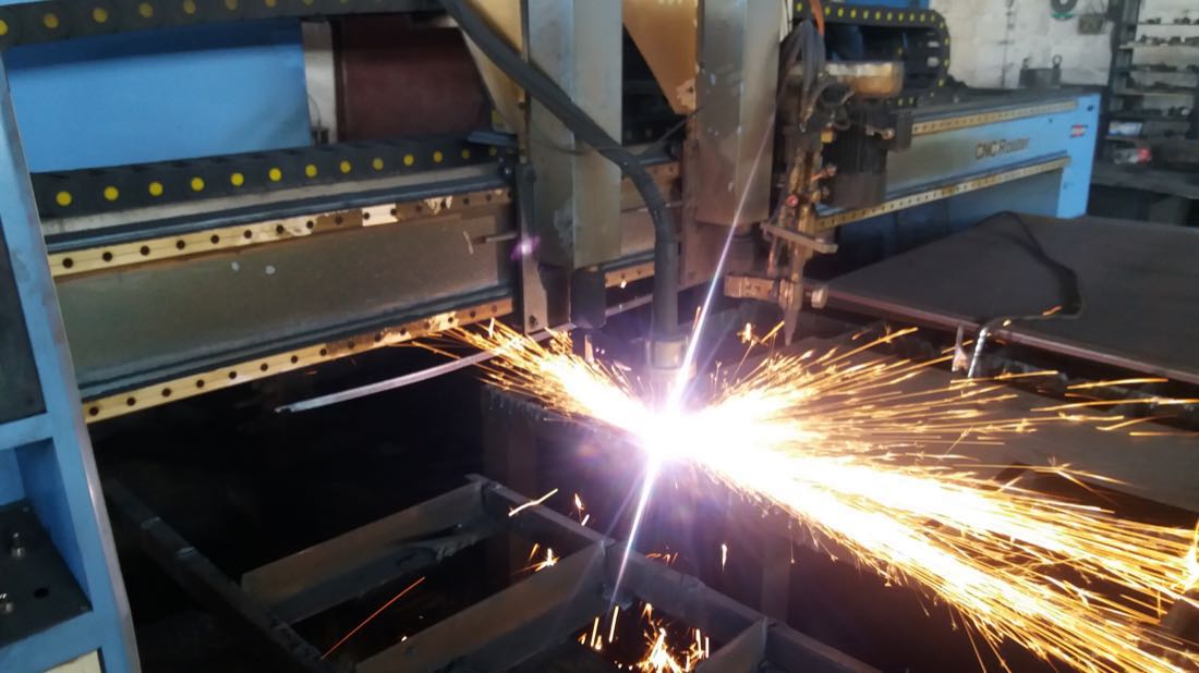
The beast that we would use that day is the plasma cutting machine:
Plasma cutting uses a jet of plasma to cut through electrically conductive materials, such as stell, aluminium, copper, etc. This jet is formed by ionizing a gas (oxygen, air, etc) and accelerating it by closing an electric circuit between the plasma torch and the material to be cut.
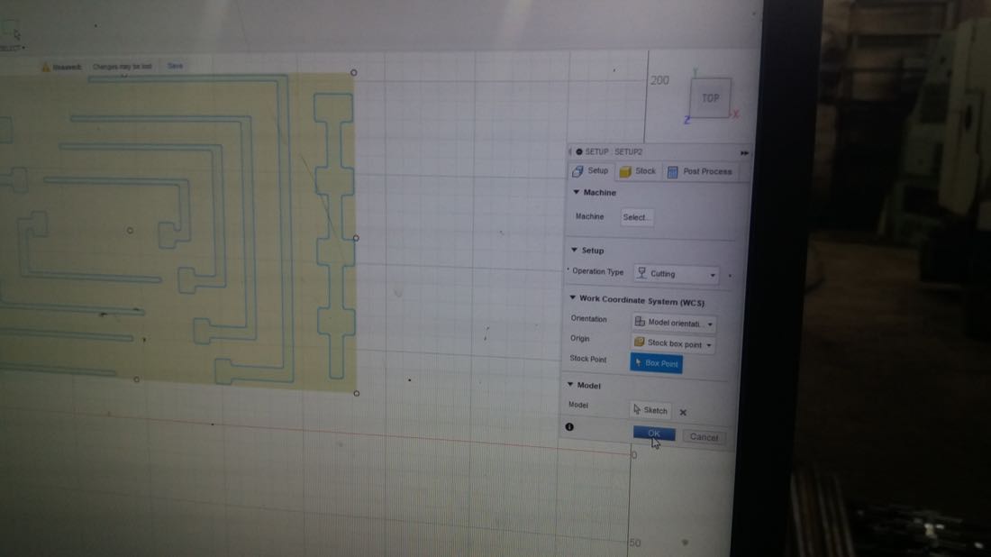
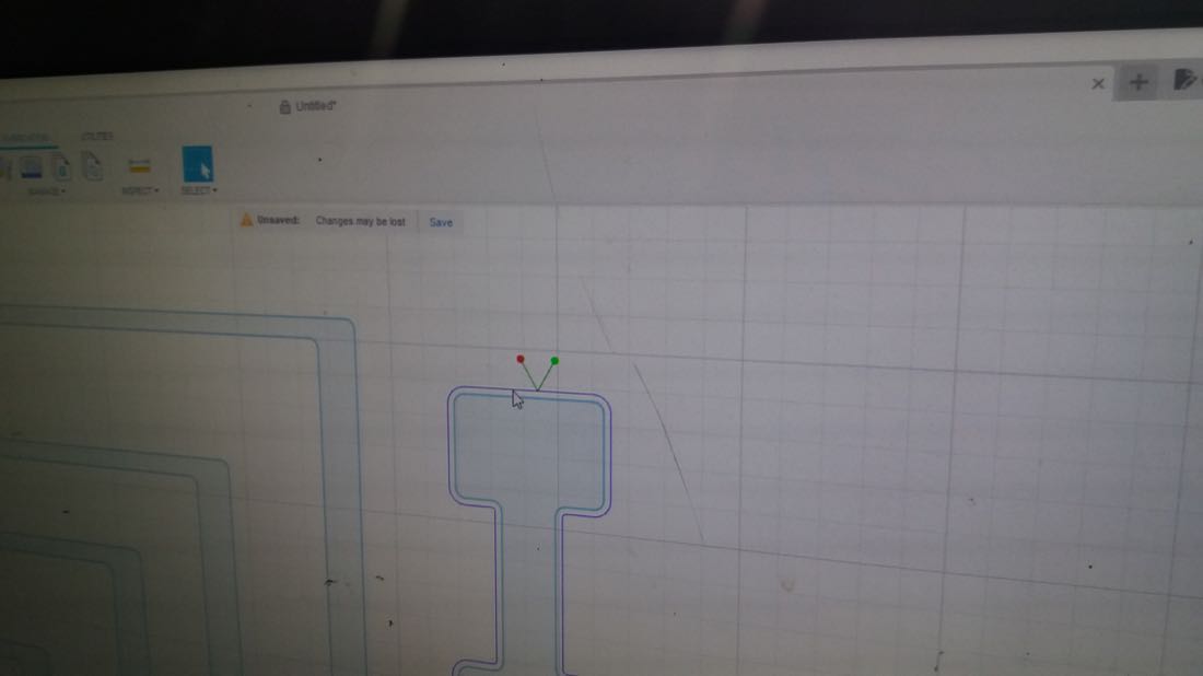
Once I had my design ready, Ashot helped me generate the g code inside fusion. First, we had to set the X/Y zero at the right place:
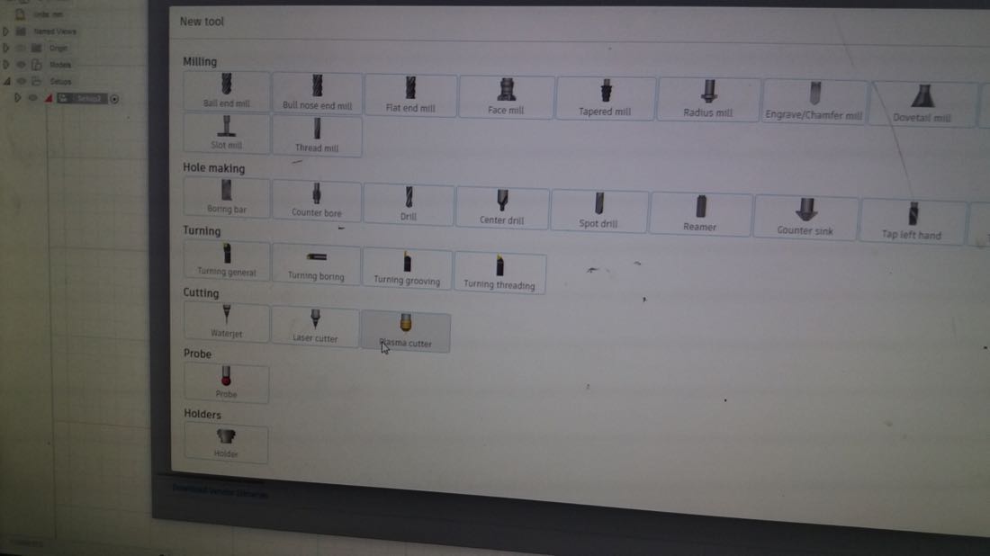
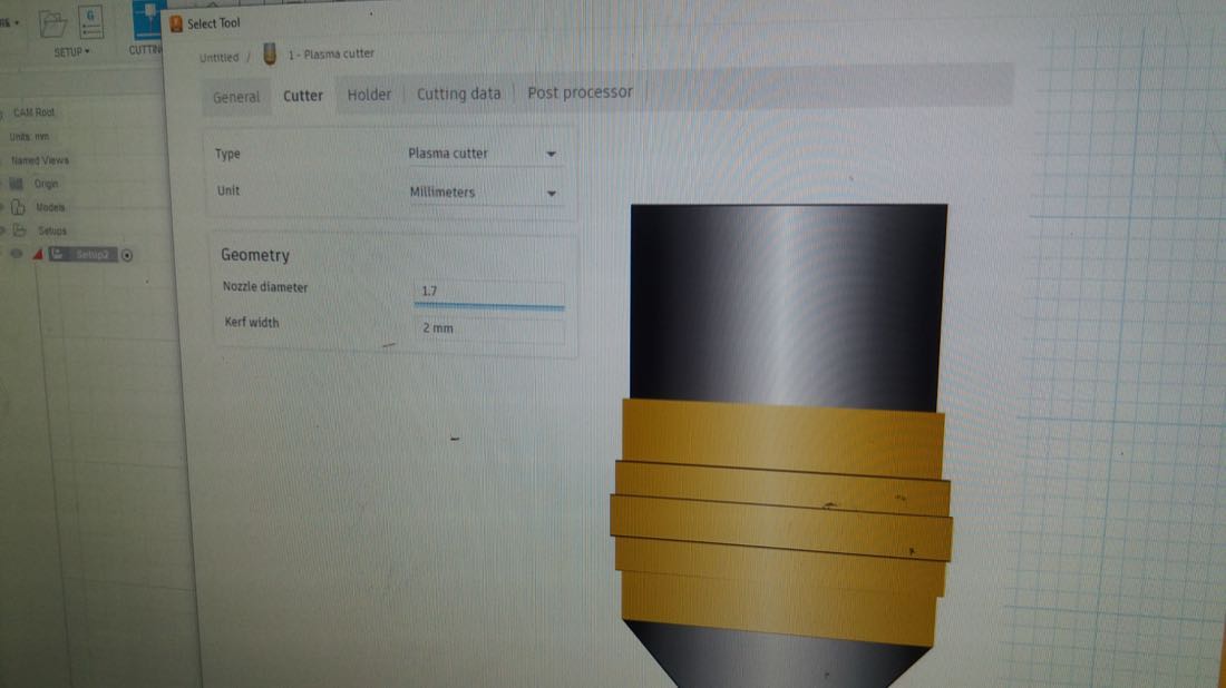
Then, we chose the tool we would use:
We adjusted the parameters to fit the specific tool installed on the CNC:
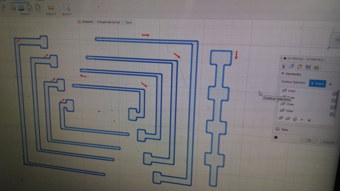
We also set the toolpath to cut outside of the line:
We referred to the manual to set the voltage and the cut speed according to steel thickness (in our case, 2mm). We had to look at the “Unshielded” mild steel parameters, Sorry for the blurry picture, I took it quickly and didn’t see that it had this quality:
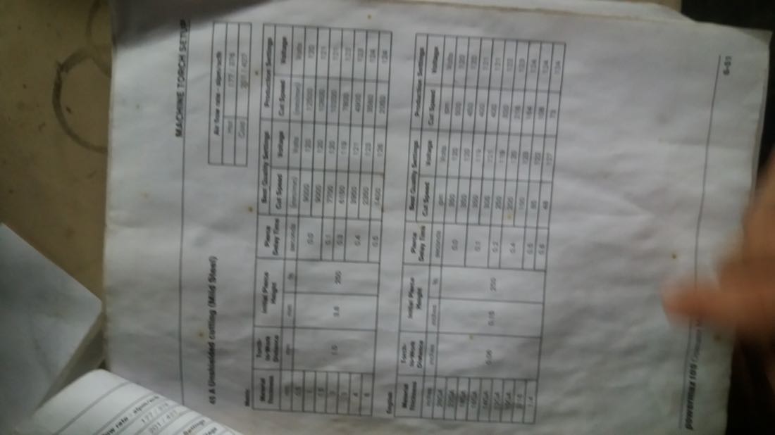
However, Ashot said that his plasma cutter wasn’t exactly corresponding to the one from the manual, and he therefore changed few parameters.
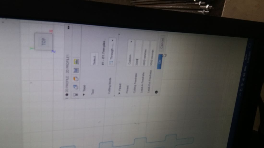
We started with feedrate of 3000 mm/min:
We adjusted the parameters for starting the cut. This is important, since it often leaves a mark where it starts:
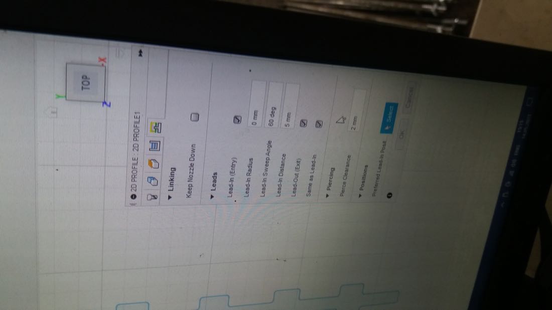
We chose the place for entering the cut:
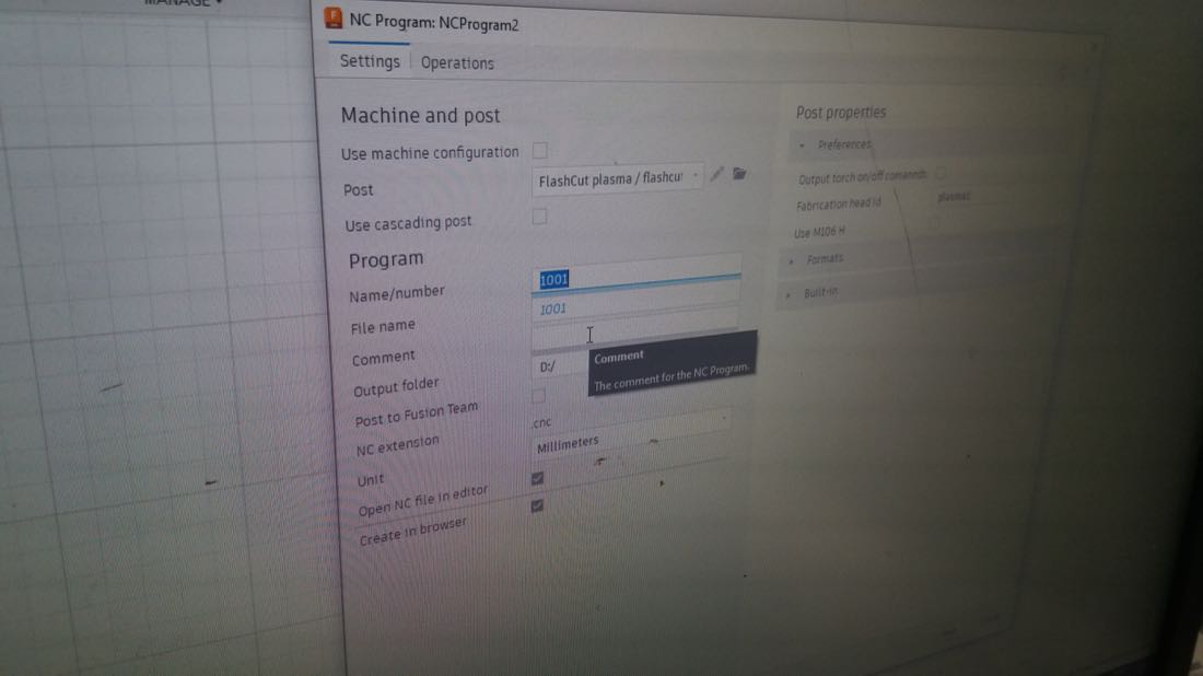
We sent the job to the machine:
And did the final preparation before cutting:
We had to start these devices, but I unfortunately forgot what was their role:
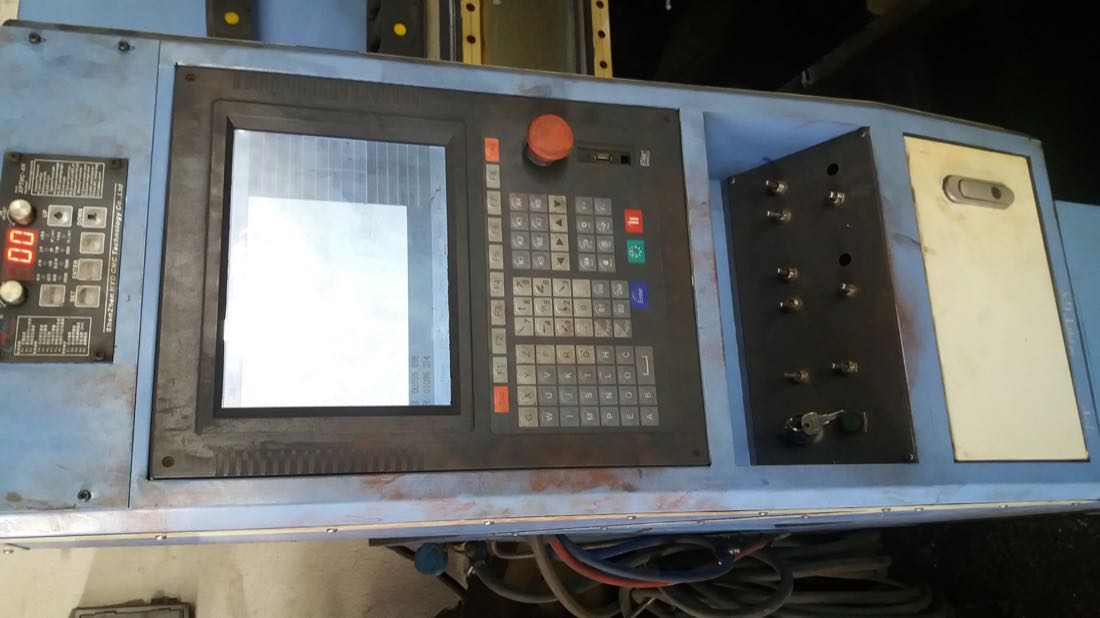
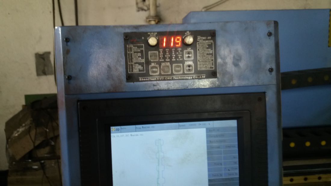
We then did the final setup on the CNC console:
We set the voltage to 119 volts:
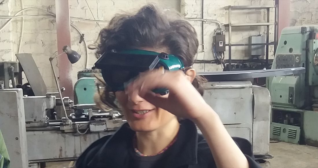
As Anoush brilliantly demonstrates, we had to wear some appropriate glasses if we wanted to look at the cutting:
I found the cutting process itself beautiful:
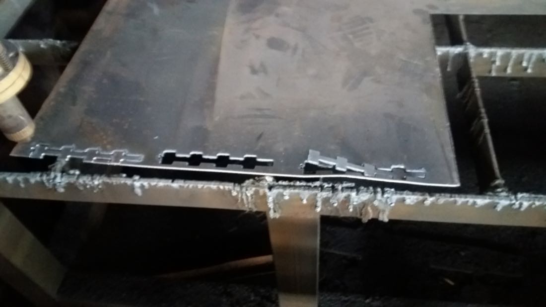
Unfortunately, the first cuts weren’t successful:
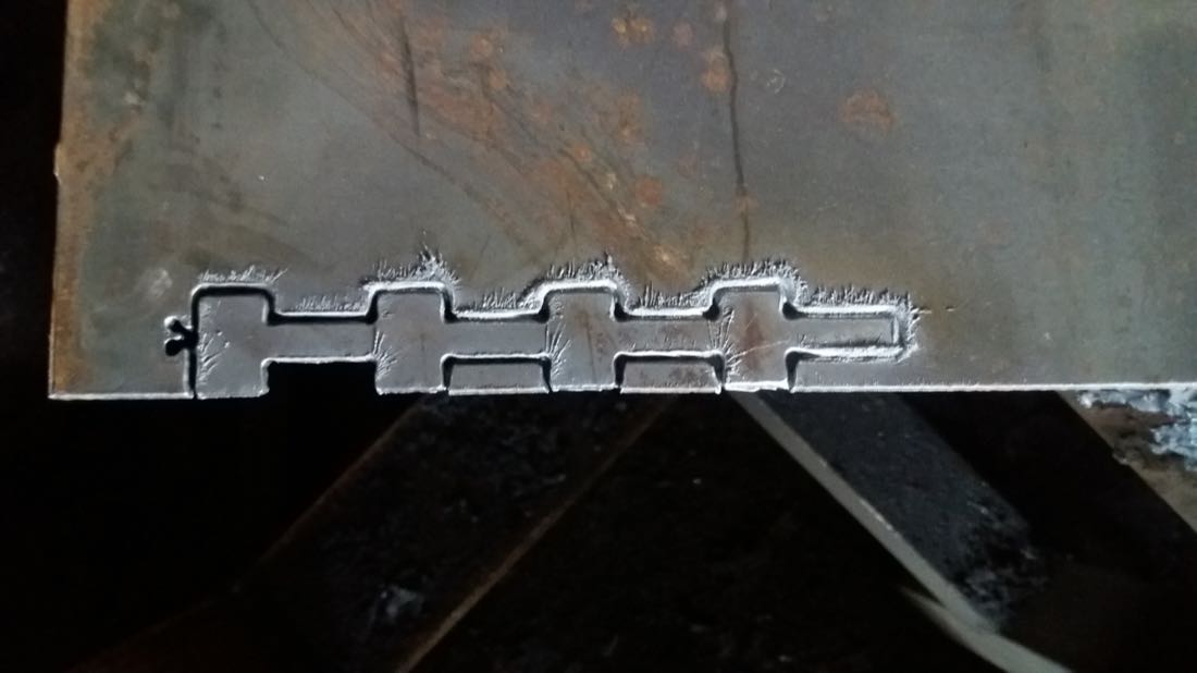
We decided to lower the cut speed to 1300 mm/min, and this time, it cut through:
Post processing of metal pieces
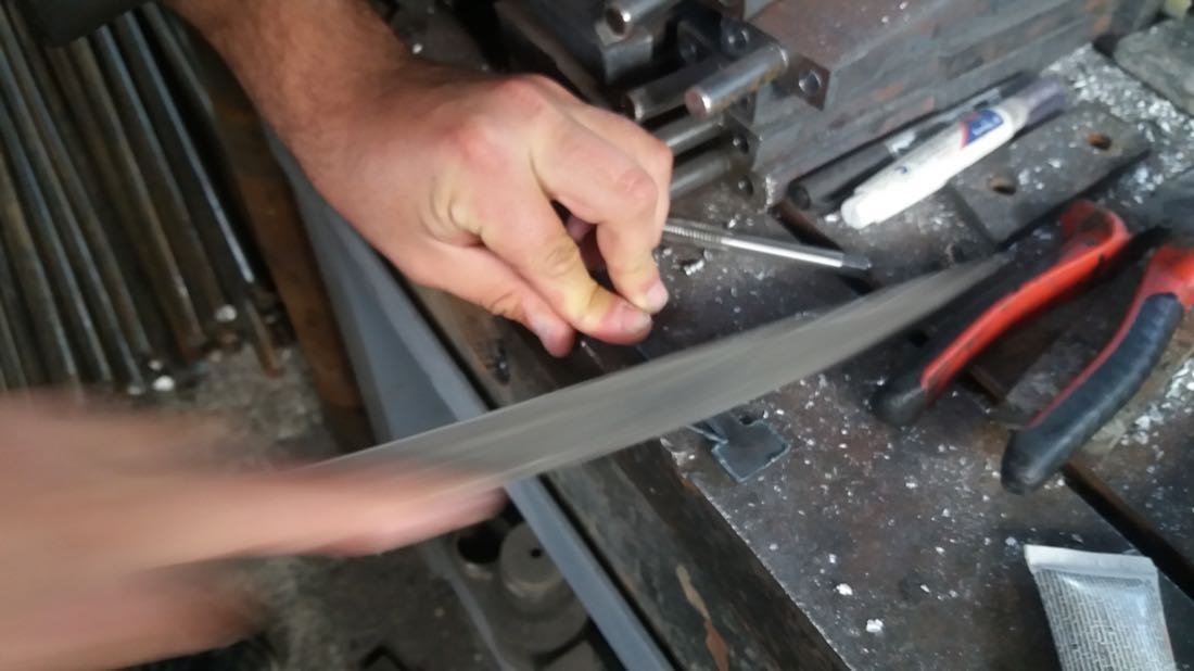
The plasma cutter does a pretty rough job, so the parts have then to be post processed. Some metal melts and flows down with gravity close to the cut. In order to remove this, I first tried to remove it with a file, but it was too tedious:
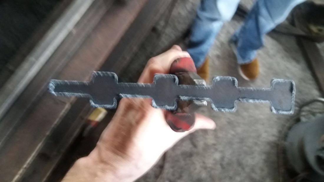
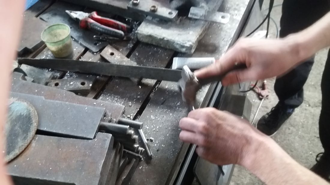
Ashot told me that it was much easier to remove it with a hammer by simply hitting the edges:
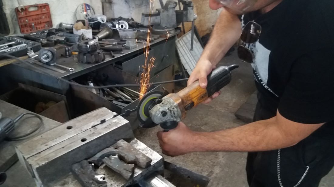
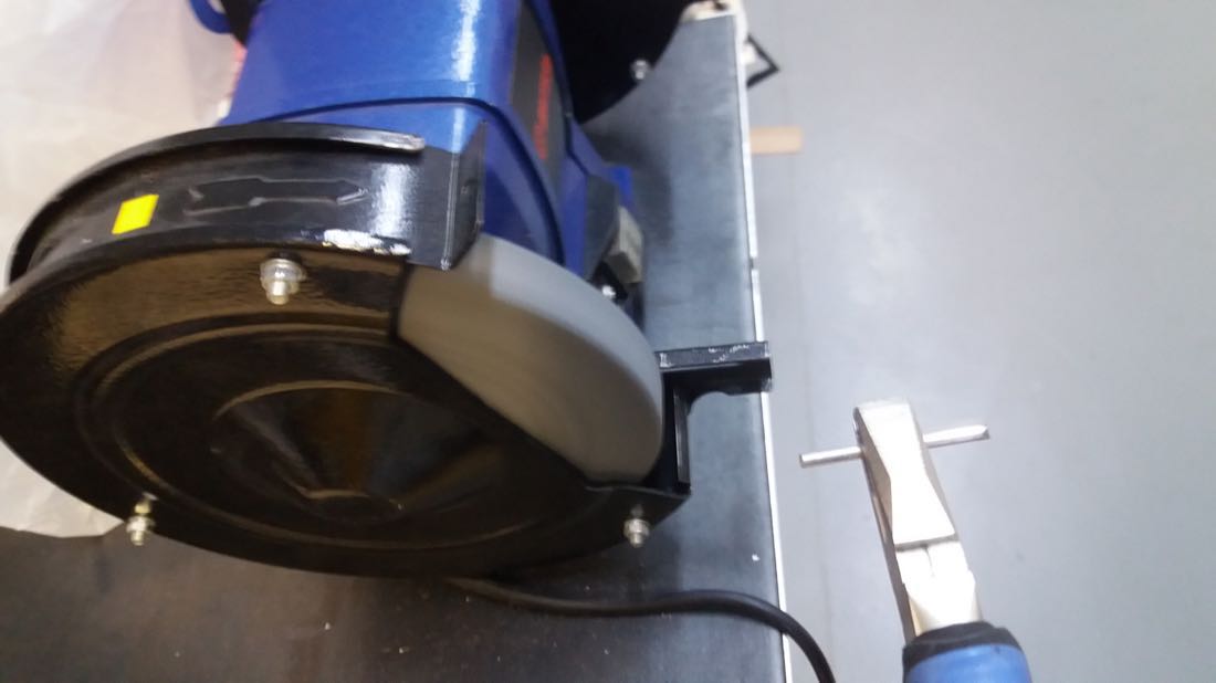
Derenik helped me to further grind what I couldn’t remove with the hammer:
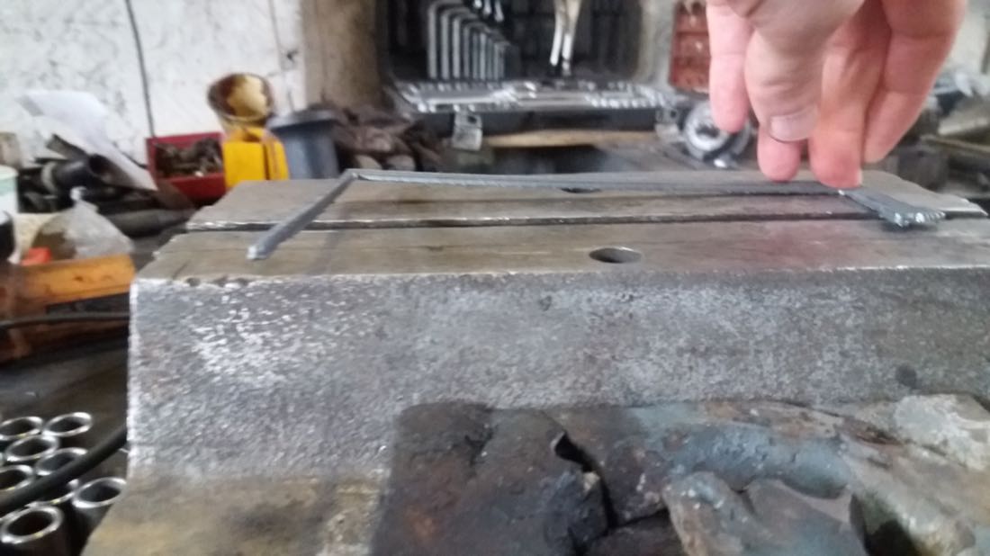
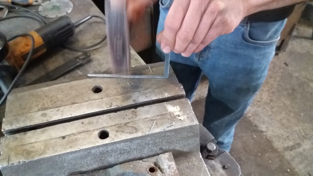
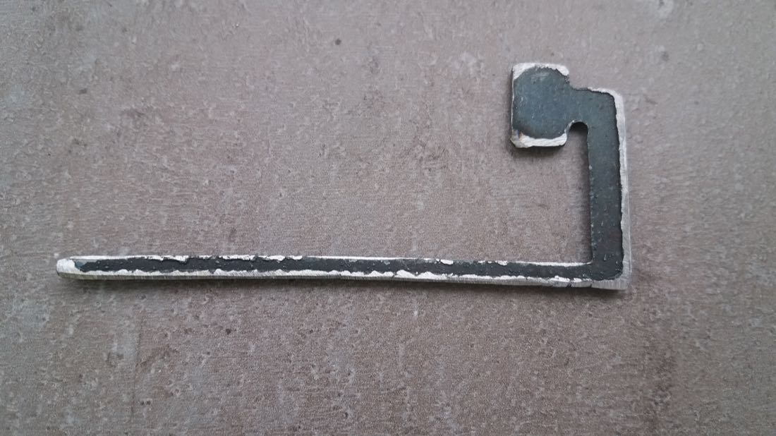
When I arrived with my designs, Ashot told me that it would be hard, because such thin metal pieces would bend under the heat. Indeed, some bending occured and it would be a big problem if I needed very accurate cuts. However, with the tolerance I wanted, the bending was bearable, and I could fix some of it:
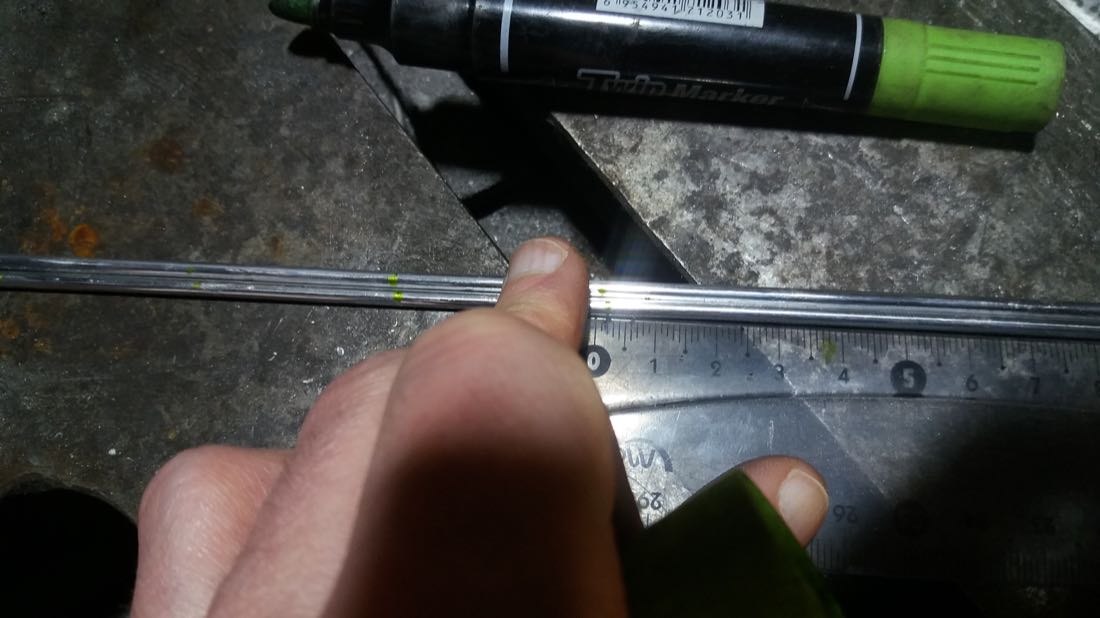
Since I had many small connections that would take time and would probably yield a poor result if done with the plasma, I cut these parts out of 3mm aluminium cylinders used for welding. First, I marked the desired length as accurate as my tools would allow:
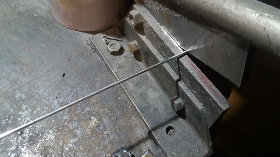
And then I cut my 48 small pieces:
Since we only had a limited amount of time at the factory, I couldn’t finish everything I wanted to do. I further grinded some of my parts back at the lab.
Before:
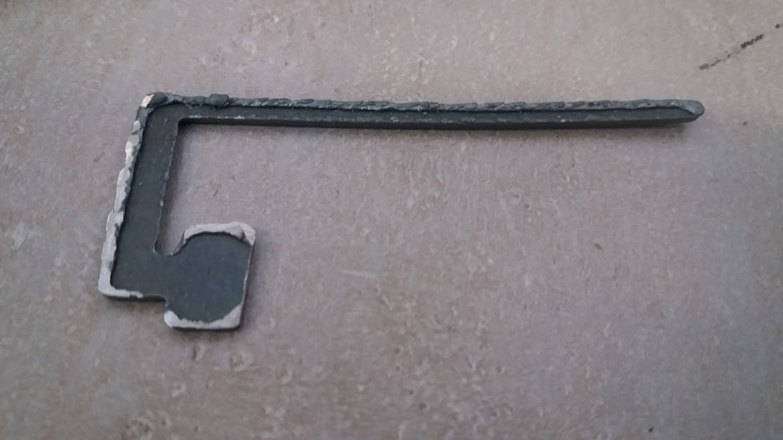
After:
Laser cutting
This week also gave me the opportunity to use again the laser cutting machine that I used a couple of months ago. I had forgotten a lot of the procedure, and I was happy that Nanor, a volunteer at our Fablab, could coach me for the start.
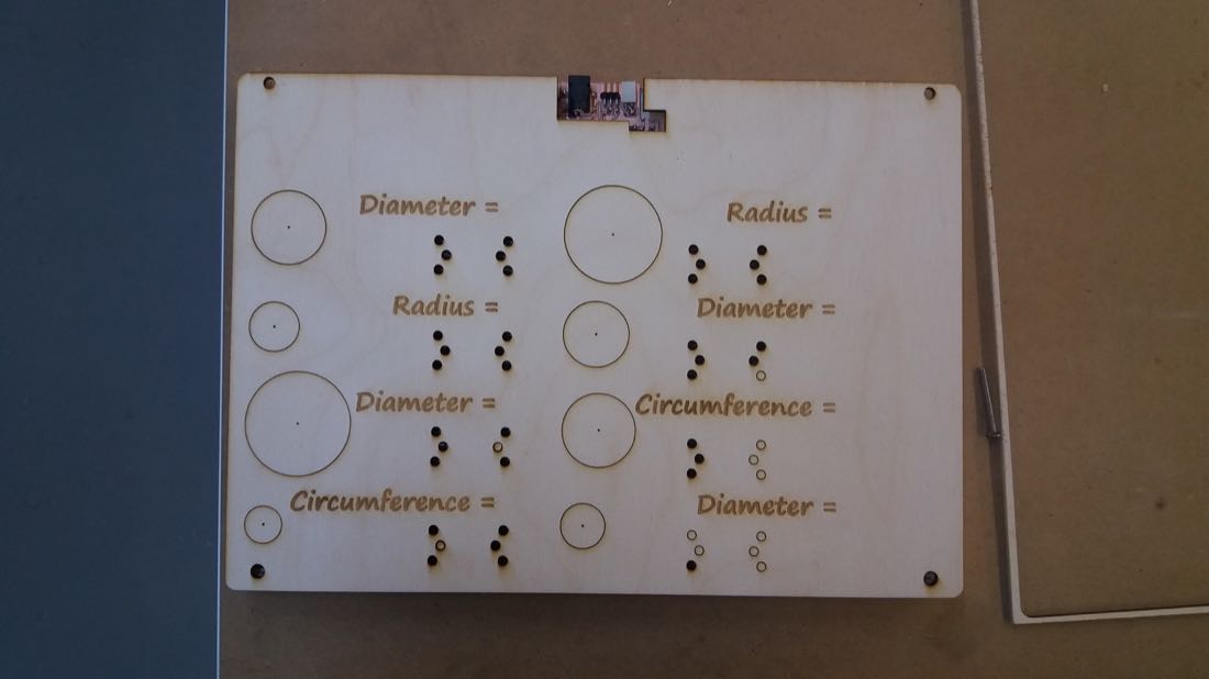
This is the cover of the device:
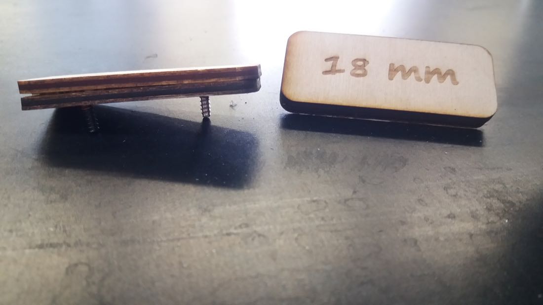
I also cut some small rectangles for the answers. I needed to connect 2 of the 6 holes to create up to 9 different combinations:
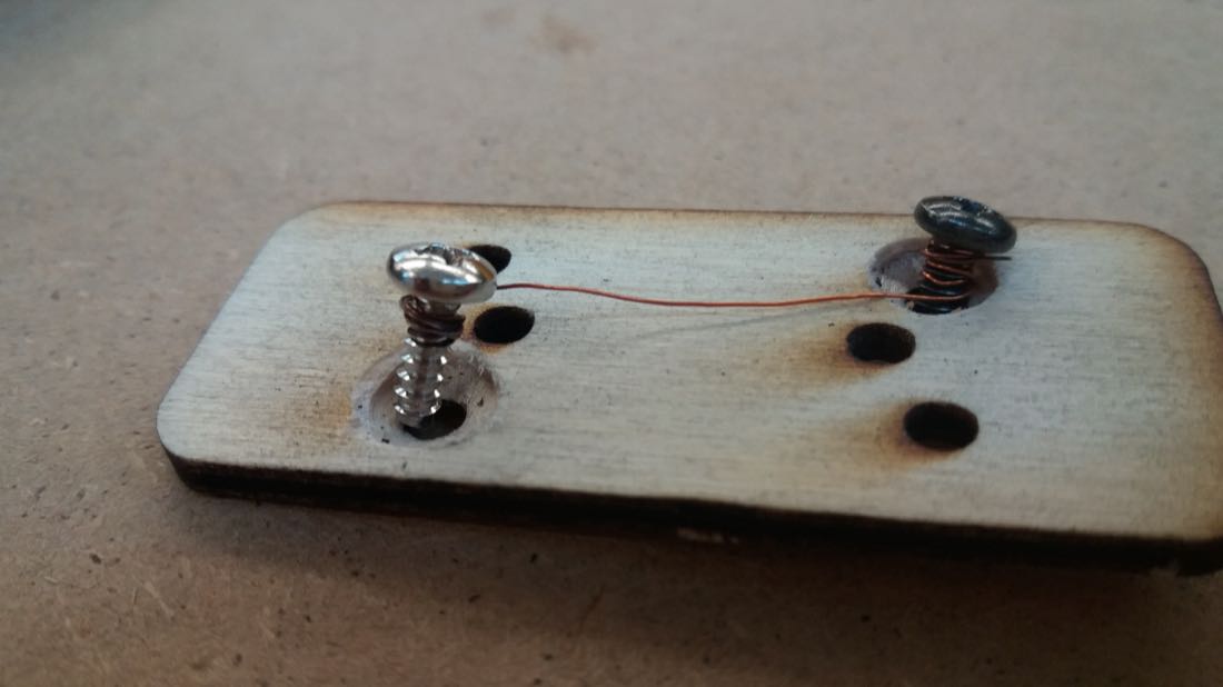
I then glued the two parts together:
The answers can then be put in place:
Combining the parts
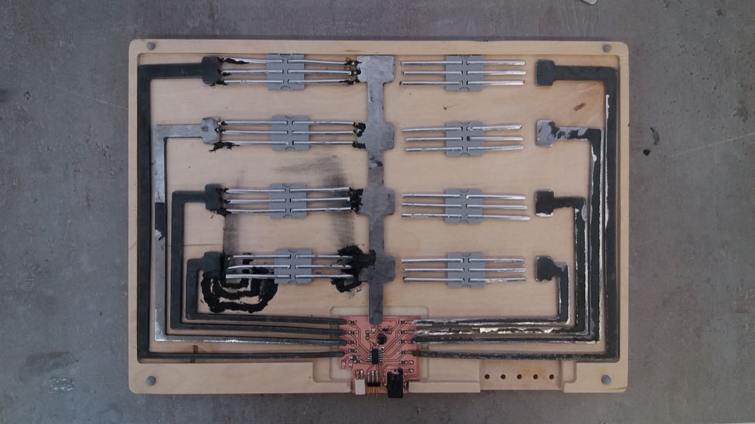
Now that I had all the parts, I needed to combine them… or so I thought:
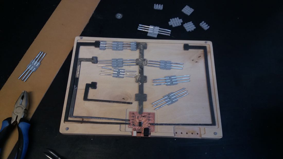
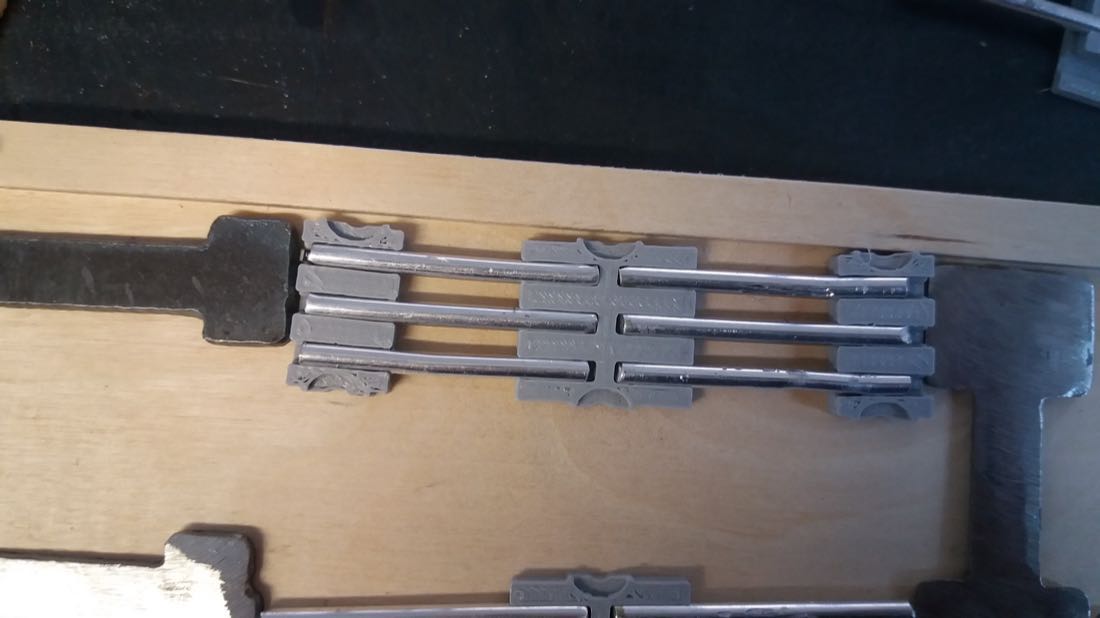
I first adjusted the length of the aluminium connections:
I then embedded the resistors inside the plastic mounts that I 3D printed:
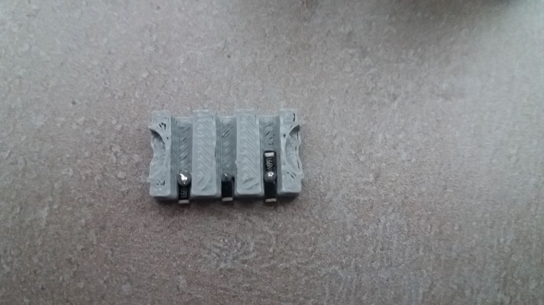
It took me a lot of time to make 1 out of 8 connections set:
And it wasn’t yet connected to the large connection tracks… I started to think that this week wouldn’t go as planned.
I embedded all the resistors inside their plastic mounts:
However, when I tried to connect them to the aluminium connections, things didn’t go as planned… After many many trials, I gave up.
During the regional review with Finland, Ivan suggested to use some kind of conductive paint. Since we had some in the lab, I gave it a try. The paint was probably old and it had turned into paste, but I tried anyway… for an ugly result.
Before:
After:
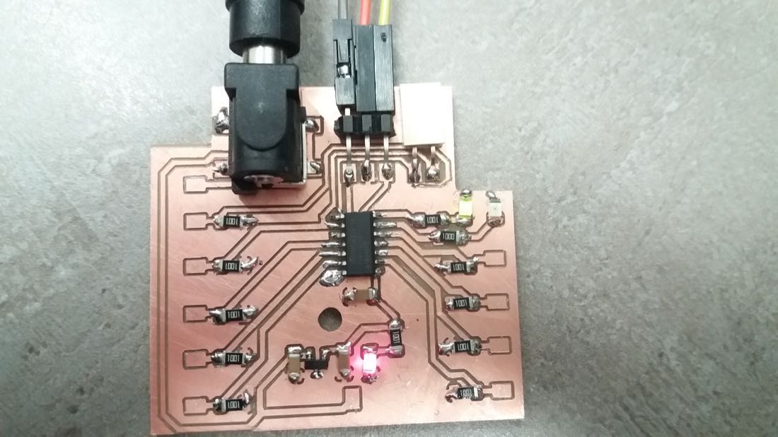
Programming the board
To program my board, I followed this tutorial. Unfortunately, as I failed to get more than one set of connections working, this code only works for one of the analog pins. Since I was able to start working on this only Wednesday morning, I didn’t have the time to fine tune it and this codes filters 7 out of 8 wrong positions.
#define redLED 4
#define greenLED 5


int analogPin = 3;
int raw = 0;
int Vin = 5;
float Vout = 0;
float R1 = 1000;
float R2 = 0;
float buffer = 0;

void setup() {
  pinMode(redLED, OUTPUT);
  pinMode(greenLED, OUTPUT);

  for (int i = 0; i < 3; i++) {
    digitalWrite(greenLED, 1);
    digitalWrite(redLED, 0);
    delay(700);
    digitalWrite(greenLED, 0);
    digitalWrite(redLED, 1);
    delay(700);
  }
  digitalWrite(redLED, 0);
}

void loop(){
  raw = analogRead(analogPin);
  if(raw){
    buffer = raw * Vin;
    Vout = (buffer)/1024.0;
    buffer = (Vin/Vout) - 1;
    R2= R1 * buffer;
    if (R2 < 20000 && R2 > 1000) {
      digitalWrite(greenLED, 0);
      digitalWrite(redLED, 1);
    } else if (R2 <= 1000) {
      digitalWrite(greenLED, 1);
      digitalWrite(redLED, 0);
    } else {
      digitalWrite(greenLED, 0);
      digitalWrite(redLED, 0);
    }
    delay(100);
  }
}
This is the video showing the proof of concept. Unfortunately, the green LED is not very bright (but it is visible when played in full screen).
Conclusion
I am quite disappointed by the result of this week’s project. I had the idea of making this kind of educational game for some time and thought that this week would be a good opportunity to implement it. However, I encountered some difficulties trying it out. The first problem was the small size of the parts that I needed to cut using the plasma torch. Since they were thin, the heat produced during the cutting process deformed them. I was able to straighten them afterwards and since I didn’t need a tight tolerance on these parts, the result was satisfactory.
The bigger issue I faced occured when trying to connect the parts made out of steel with the copper PCB or the aluminium connections. I struggled for a long time to achieve a reliable connect, but without success. A solution could be to design a mechanism that pushes the different parts against each other to connect them. Since I didn’t think through from the beginning, such a mechanism was hard to implement afterwards.
All in all, despite the failure of my project, this week was full of valuable lessons.
Files
CAD file for the educational game
CAD file for the first connection holder
CAD file for the second connection holder